Table of Contents
Advertisement
Quick Links
Advertisement
Table of Contents

Related Manuals for Danfoss MPCAN


Summary of Contents for Danfoss MPCAN
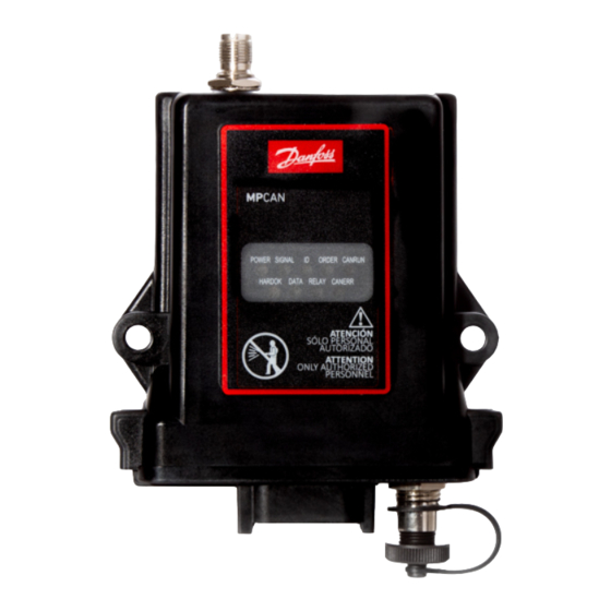
- Page 1 User Manual Remote Control MPCAN Receiver www.danfoss.com...
- Page 2 User Manual MPCAN Receiver Revision history Table of revisions Date Changed March 2022 Updated safety instructions and technical descriptions 0201 January 2019 Rebranded to Danfoss Power Solutions 0101 © Danfoss | March 2022 BC292573933619en-000201...
-
Page 3: Table Of Contents
Safety instructions FCC rules......................................4 General safety....................................4 Safety warnings....................................5 Technical description Dimensions......................................6 Hardware description..................................7 MPCAN detailed description................................ 7 Installation Receiver installation..................................9 Input and output configuration............................... 10 STOP category 3 PLe................................10 Pinout......................................11 Troubleshooting MPCAN Receiver Faceplates..............................12 MPCAN400-900MHz LED troubleshooting...........................12... -
Page 4: Safety Instructions
• Service the equipment periodically. • When carrying out repairs, use spare parts supplied by Danfoss only. Warning Potential damage to the operator or the product. Do not use this product on machines in potentially explosive atmospheres unless the model is ATEX/RATEX certified to work in such conditions. -
Page 5: Safety Warnings
Avoid knocking or dropping the product. • Do not use the product if a failure is detected. Changes or modifications not approved by Danfoss can void the user's authority to operate this product. Quick reference precautions © Danfoss | March 2022... -
Page 6: Technical Description
User Manual MPCAN Receiver Technical description MPCAN dimensions Dimensions in mm 35.99 92.25 29.20 101.60 R 3.70 118.73 © Danfoss | March 2022 BC292573933619en-000201... -
Page 7: Hardware Description
User Manual MPCAN Receiver Technical description MPCAN hardware description Fixing slots (fixed assembly or anti-vibration) External antenna Removable internal EEPROM External LEDs RF Module CAN bus termination DEUTSCH connector pinout Tether connection STOP relays Internal fuse, 7.5A MPCAN detailed description... - Page 8 Associated transmitters (400 - 900MHz) Ikargo1, Ikargo2, T70 1, T70 2, T70 1 HALL, T70 2 HALL, T70 1 ATEX, T70 2 ATEX, IK2, IK3, IK4 Associated transmitters (2.4 GHz) Ikompact, Ikore, IkoreB, IK2, IK3, IK4 © Danfoss | March 2022 BC292573933619en-000201...
-
Page 9: Installation
User Manual MPCAN Receiver Installation MPCAN receiver installation The below information describes hazards to be aware of during installation and steps to locate the receiver. Risk of shock Completely shut down the machine when installing the receiver. Check the power supply and shut off the main switch to disconnect the interface cable between the receiver and the machine's electrical box. -
Page 10: Input And Output Configuration
This receiver has four digital outputs or four digital inputs. The hardware is shared by these inputs and outputs and they are chosen by EEPROM configuration. Each input and output cannot be configured together at the same time. The MPCAN includes a 7.5A internal fuse. Internal Vcc MPCAN STOP category 3 PLe Stop function is performed by two relays in series or parallel. -
Page 11: Pinout
Parallel external connection V in G ND STOP2 STOP2 STOP2 +OUT STOP1 STOP1 STOP1 +OUT MPCAN pinout Description CANH KSTOP 2.2 KSTOP 1.2 K4/IN4 K3/IN3 K1/IN1 K2/IN2 KSTOP 1.1 KSTOP 2.1 CANL © Danfoss | March 2022 BC292573933619en-000201 | 11... -
Page 12: Troubleshooting
No radio signal detected LED on + transmitter switched Radio channel occupied Change transmitter's frequency channel LED on + DATA switched off Radio channel occupied by non Danfoss system Change transmitter's frequency channel DATA Green; pulsing Receiving good frames LED off + DATA LED on No valid ID;... -
Page 13: 2.4Ghz Receiver Led Troubleshooting
Check CAN wiring and initialized Configuration(EEP or Expansion ID#), Check Bus Termination. Red | 1 Long + 1 short CAN Signature ERROR Check Signature in Compliance pulse Block and EEPROM are the same. © Danfoss | March 2022 BC292573933619en-000201 | 13... - Page 14 Green | fast pulses Pre operational Status, Receiver waiting for the Controller must send the controller. Operational code to the Receiver. Green | continuous Receiver connected to the CAN network and operational 14 | © Danfoss | March 2022 BC292573933619en-000201...
- Page 15 Phone: +86 21 2080 6201 Danfoss can accept no responsibility for possible errors in catalogues, brochures and other printed material. Danfoss reserves the right to alter its products without notice. This also applies to products already on order provided that such alterations can be made without subsequent changes being necessary in specifications already agreed.
Need help?
Do you have a question about the MPCAN and is the answer not in the manual?
Questions and answers