Advertisement
Quick Links
Advertisement

Related Manuals for Honeywell NOTIFIER AM1000


Summary of Contents for Honeywell NOTIFIER AM1000
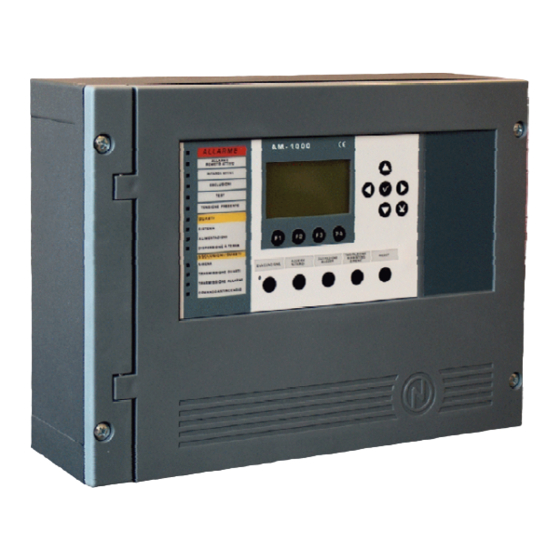
- Page 1 AM1000 Programming manual Analog fire panel...
- Page 2 LIMITS OF THE DETECTION SYSTEMS An alarm or fire detection system can be very useful for the timely warning of every dangerous events like fire, robbery or a simple infringement; sometime it can automatically manages the events (diffusion of messages for the evacuation, automatic extinguishing of fire, to interface with TVCC systems, block of the doors or ways leading up, automatic alert to the authorities, etc.).
- Page 3 INDEX DESCRIPTION COMMAND AND SIGNALINGS FRONTAL DISPLAY BRIGHT SIGNALS OF THE FRONTAL DESCRIPTION USER INTERFACE FUNCTIONS LIST KEYBOARD FUNCTION DESCRIPTION FOR DATA INSERTION IN DATA PROGRAMMING FILES STAND-BY CONDITION ZONE IN ALARM CONDITION ZONE IN TROUBLE CONDITION SYSTEM IN TROUBLE CONDITION CONDITIONS WITH ALARM FROM ZONE IN TEST VISUALIZATION OF THE LIST REGARDING EXCLUDED DEVICE AND ZONE PROGRAMMING MENU...
- Page 4 LINE: physical line linea on which the detectors, the addressed sounders, any addressed input and output modules are connected. POINTS: are the detectors and the addressable modules that can be connected to the control panel. ZONES: are grouping of points. They give the possibility to identify the position of an event. It is possible to have a maximim of 50 zones.
- Page 5 RESET : the pressure of this key delete the memory of the alarms and points troubles present at the moment. De-activate the sounders and turn off the lighted signals fo the detectors in alarm. To do this procedure it is necessary to know the password of level 2. Keys to be used: DURING THE PROGRAMMING OR TO INTRODUCE THE PASSWORD ARROWS : To be used to select something or to introduce some characters.
- Page 6 Bright signals of the Frontal ALARM (Red) : It is flashing kf at least a device is in alarm, and it has not been identified. It is fixed lighted Acceso if all the alarm status have been identifed. REMOTE ALARM (Red) : It remains lighted if the output to the transmission devices for the fire alarm has been activated.
-
Page 7: Functions List
Functions List Functions EN.54 Level Manufactured Default Password Visualisation of alarms and troubles Level 1 no one Visualisation of cancelled indication Level 1 no one Identification of alarms and troubles Level 1 no one Settino of delay (dedicated push-button) Level 1 no one Visualisation of excluded zones/points Level 1... - Page 8 It is possible to insert the passwords, when requested, selecting the necessary digit using the e functioning keys and confirming each letter with return When it is introduces a wrong password the system visualize the following message: “WRONG PASSWORD : xxxxx “ where “xxxxx” is a 5 character code, it is possible to signalize this code to the authorized technical assistance.
-
Page 9: Stand-By Condition
Stand-by condition The following screen is visualized when the control panel is in stand-by condition. Icon for the indication of the control panel status. Without alarm and troubles the NOTIFIER symbol is visualized. With excluded points/zone an exclamation marks ( ! ) is visualized. With alarms the symbol of a Flame is visualized. - Page 10 Zone in alarm Condition The following screen is visualized when there is a zone in alarm. First zone in alarm. Programmed text for the Hour and date of the event . zone. Meter of the zone in alarm. Last zone in alarm. Hour and date of the Programmed text for the zone.
- Page 11 Device in trouble Programmed text for the device. With further pression of the return key the visualization of the point name is alternate with the detail of the trouble, see following plate: Device in trouble Description of the trouble typology. Pressing the escape key or let inactive the keyboard for 15 sec.
- Page 12 Conditions with alarm from a zone in test Alarm from the Hour and date of the event test zone Pressing the escape key it is visualized the list of the tested devices of the zone with the indication of the name of the point, see following plate: Device in alarm S = detector...
- Page 13 Ù Ù Pressing the function key F1 it is possible to gain access to the programming menù, that allow the possibility to perform the initial configuration of the system ant to make any changes in the programming. To access to the menù it is necessary to insert the Level 4 password (default password: 44444). To insert the password look up the editing function described on a pag.
- Page 14 the editing function is activated, with the 56 With the first pressure of the return key It is possible to select the line style (NORMAL - LOOP), press the return key to confirm the programming. Press the right key 4to modify the parameter priority scan following paragraph With the 56select the voice to be modified (“Last.
- Page 15 With 56it is possible to select the voice that we want to modify (“Siren “ o “Tx Alarm”), the editing function is activated with the pressure of the return key The data are introduced with 56and confirmed with the return key Press the right indicator 4 to modify the audit on the detectors, see the following paragraph: AUDIT TIME allow the control panel to audit the detector, for a fixed time, before to confirm any alarm.
- Page 16 TROUBLE TX: is of the delay time for the Trouble output (trouble trasnmission with dialer). With 56it is possible to select the voice that we want to modify (“Main“ , “Trouble Tx” ,) the editing function is activated with the pressure of the return key The data are introduced with 56and confirmed with the return key •...
- Page 17 Programming of the Points If we select the voice Points, from the programming menù, we display the screen that allow the complete programming of all the devices ( detectors and addressable modules) connected to the line as per following plate. •...
- Page 18 Address of the detector Number of the assigned zone Address of the synoptic to be activated in case of alarm from the detector Press the F1 key to Press the F2 key to programm the previous programm the following detector detector Address of the detector Programming “YES”...
- Page 19 • • From the Points menù it is possible to enter in the complete programming procedure for modules through the selection of the “Modules” voice, to confirm press the return key This procedure is composed of 3 programming files where the data insertion is like the editing function (page The files for the inputs modules are: First File (Progr.
- Page 20 Address of the module Thanks to the tracking function the alarm signal from the input module ( that is associated to an output module throught CBE) allow the output module to follow the status of the input module It is possible to disconnect the led flashing of the module during the query of the line.
- Page 21 Address of the module CBE equation Address of the synoptic to be activated in case of alarm from the module Press the F2 key to Press the F1 key to programm the following programm the previous module module Address of the module Enabling of the manual silence Enabling of the self-reset It is possible to disable the led flashing of the...
- Page 22 The function “Remove from ... to ..” allow the delete, from the programming of the control panel, a whole consecutive block of points inserting the address of the beginning and of the end. The functions Copy and Paste allow the programming of the blocks points and can be used if the devices have consecutive address and common parameters.
- Page 23 When the system finds more devices with the same address it is displayed the message as per the nearby plate showing the address. The user wil be able to identify the devices with the same address through the lighting of the relative leds.
-
Page 24: Input Modules
Sumarizing Type ID for modules tables INPUT MODULES WIRING Type of Device ABBREVIATION MON3 MMX-1 Monitor Module Monitor Module used to monitor N.O. Contacts. Comlpies EN54 MMX-1 Monitor Module Monitor Module used to monitor N.O. Contacts. NOT Comlpies EN54 SCON MMX-2 Monitor Module Monitor Module used for convetional 4-wire smoke detectors, not detected durinig autoprogramminig. - Page 25 Control Module configured as a Form-C relay, , which will be activated whenever an alarm conditions APND occurs. It will be reset via ACK operation. Control Module configured as a Form-C relay, , which will be activated whenever an alarm conditions occurs.
- Page 26 Type ID for the UDS unit For the Uds panels two specific Type ID are reserved, UDS1 and UDS2. We remember that the UDS can be installed from the the address at the beginning of the dozen (excepted from 0 to 9), using from a minimum of 2 to a maximum for 6 address. The standard installation, compatible with the UDS-IN unit, occupe the two first address to which is assigned the Type ID this kind of operation is allowed for the first address and is automatically extended to the...
- Page 27 Groups menù A group is a software devices whole that allow the associations. When a detector or a module (member of the group) are in alarm, the group is activated. If an output module is member of the same group, it will be activated. This procedure is composed of 3 programming files using the editing procedure for the insertion of the data (see page 5).
- Page 28 • • Insert the number of the high sensibility Group . Insert the number of the low sensibility Group Press the F1 key to Press the F2 key to program the previous program the following Group Group HIGH AND LOW SENSIBILITY GROUPS It is possible to define two groups (sorted out from the reverse at disposal), to which it is necessary to program a CBE equation, using the TIME user, to make them working only during a fixed time.
- Page 29 Up/Download This function allow the programming of the AM1000 control panel using the PK1000 software. Clear programmation : This function delete all the data regarding the installation contained in the non-volatile memory of the control panel. Ù Ù Pressing the F2 functioning key we enter the Utility menù, where are collected some functions generally used by the technical staff.
- Page 30 Parameters To insert the data please see the editing function. Where : • • • • This procedure is composed of 3 programming steps using the editing procedure for the insertion of the data (see page 5). DRIFT WARNING - Enabling this function the control panel produce a signal when a detector exceed the 70% of his alarm threshold for more than 5 minutes.
- Page 31 Insert the parameter for the signaling of trouble for invalid reply, (expressed as number of polling questions on the line) . Insert the parameter for the signaling of trouble for wrong Type ID (expressed as number of polling questions on the line) . Insert the parameter for the signaling of trouble of open circuits, (expressed as number of polling questions on the line) .
- Page 32 Historical archives : This function allows the user both the visualization of the archives content and the cancellation. The historical archives has capability of a maximum of 500 events. When there are 500 memorized events, the control panel, with a new event, delete the less recent event and memorize the new one.
- Page 33 Status Reading/ Status Change : Using this function the user can display the point status and if the point is a sensor also the analog value. This value will be displayed as “percentage of the alarm threshold” programmed for this device.
- Page 34 • • Address of the point Programmable label of the point Status of the point With the 56 indicators the user can modify the output module status, setting ON and setting OFF. Press the F1 key to Press the F2 key to display the previous display the following module...
- Page 35 Mask of the modules When a module is excluded the control panel can not receive the alarm and trouble signal from it. Press the F2 key to Press the F1 key to program the following program the previous module module Mask of the zone When a zone is excluded the control panel can not receive the alarm and trouble signal from all the...
- Page 36 • • (Function not enabled) • • When the exclusion of the immediate output siren activation is operating, the Exclusion and Working Delay leds are lighted. In case of alarm the control panel delays the mentioned outputs for the programmed time (Programming menù: Prog\Syst\Timings-Alarm).
- Page 37 • • Insert the zone number (0 = inactive test function) CBE qualification • • Through this programming file it is possible to select the output to be activated in case of alarm from a device of the test zone. zona in test NONE = in case of alarm no output are activated SOUNDER = in case of alarm the sounder output is...
- Page 38 “ ” – “ ” – A typical programming of the control panel i defined CONTROL-BY-EVENT EQUATION (CBE). During the programming it is necessary to associate to every point, zone or group a CBE equation. The CONTROL-BY-EVENT equation allos the programming a some conditions that the control panel will value when the point, the zone or the group are actived, ant will execute the programmed actuations.
- Page 39 “Invalid” CBE Equation : To not programm any equation for a device it is enough to press the key ENTER when, during the programming, the equation is requested. In this case : if the device is a detector or an input module, the control panel will activate only the general visual and sonorous indications (alarm LED on the frontal, general alarm RELE’, BUZZER and any output modules programmed for general signals with the TYPE ID software).
- Page 40 Is the user who denies the operand or the serie of in brackets following operands Example: the equation of a CMX-2 module is: NOT (G23). The CMX-2 will remain active till the operando (G23) will not be in alarm: - IF the software group 23 is in alarm - THEN this CMX-2 will be deactivated.
- Page 41 Example 2: if the equation of the output module L2M90 is DEL (00.30 00.30 (AND(L1S1 L1S4))) after 30 Sec. that the detectors L1S2 and L1S4 are both in alarm the module L2M90 is activated and will remain activated for 30 seconds. NOTE if the delay introduced is = 00.00, the equation results active as became active the equation of delay start and remains active for the time fixed in the lenght...
-
Page 42: Programming Examples
Programming examples : OPTION The following example represents 3 different way to obtain a simple programming; the activation of the CMX- 2 output module as reply to a detector in alarm (or any other input device for the alarm). OPTION A OPTION B OPTION C Fire detection device...
Need help?
Do you have a question about the NOTIFIER AM1000 and is the answer not in the manual?
Questions and answers