Table of Contents
Advertisement
Quick Links
AQ250 Series
Hydronic Control Panels
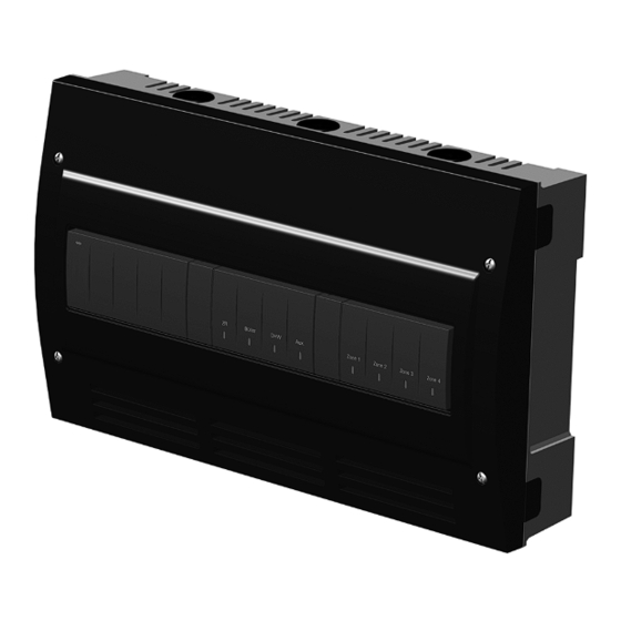
PRODUCT DESCRIPTION
The AQ250 easily converts a single-zone heating system
into a room-by-room comfort control system, or upgrades
a basic, relay-logic zoning system to intelligent Zone of
Greatest Demand control. The boiler control of the AQ250
can ensure ample supply of hot water for both space
heating and priority generation of domestic hot water for
bathing, dishes and laundry.
FEATURES
The AQ250 Series Hydronic Control Panels have the
following features:
• Zoning Control for up to four, single-stage zones or
two, two-stage zones as shipped; can be expanded to
a total of 16 zones with AQ255 or AQ257 expansion
zoning panels, and up to 64 zones by using up to
three AQ254 Add-a-Temperature expansion panels
and additional expansion zoning modules.
• Controls one boiler loop.
• Zone synchronization through Zone of Greatest
Demand control.
• Domestic hot water (DHW) priority and priority
override protection.
• Use with digital non-communicating thermostats or
AQ1000 2-wire polarity insensitive communicating
thermostats.
• Automated test feature for quick start-up and
simplified troubleshooting.
• Boiler freeze protection (in the event of network
communication failure).
• Boiler short cycling protection, post purge, and shock
prevention from cold water returning to boiler.
• Line or low-voltage output for zoning equipment
(pumps or valves).
• Integral 38 VA transformer with self resetting
electronic fuse.
IMPORTANT
To ensure correct installation and proper operation
of the control, perform the 7 installation steps in
the order numbered starting with "Installation
Preparation" on page 3.
• When using non-communicating thermostats, the
following features are not available:
• Outdoor temperature is not displayed on the
thermostat.
• Individual zone freeze protection.
PRODUCT DATA
68-0306-07
Advertisement
Table of Contents

Related Manuals for Honeywell AQ254 Series


Summary of Contents for Honeywell AQ254 Series
-
Page 1: Step
AQ250 Series Hydronic Control Panels PRODUCT DATA FEATURES The AQ250 Series Hydronic Control Panels have the following features: • Zoning Control for up to four, single-stage zones or two, two-stage zones as shipped; can be expanded to a total of 16 zones with AQ255 or AQ257 expansion zoning panels, and up to 64 zones by using up to three AQ254 Add-a-Temperature expansion panels and additional expansion zoning modules. -
Page 2: Step
AQ250 SERIES HYDRONIC CONTROL PANELS SPECIFICATIONS Temperature Ratings: Return Minimum Control Temperature: 140°F (60°C); This is the temperature at which the bypass The AQ250 Control Panels and corresponding attached pump (Aux. Pump contacts) is activated. equipment are listed in Table 1. Sensor Temperature Rating: Table 1. -
Page 3: Step
AQ250 SERIES HYDRONIC CONTROL PANELS 1 INSTALLATION PREPARATION Check That You Have All the Necessary Equipment For a NOTES: Throughout these instructions, the following Successful Installation terminology conventions are used: — AQ150 refers to the AQ15000B Control Module; • AQ2000 Series components: —... -
Page 4: Step
AQ250 SERIES HYDRONIC CONTROL PANELS perature using LOAD reset, but not OUTDOOR For these the two exceptions, the bottom terminals of the reset, as the AQ250 panel does not have input ter- Transformer and Control Module carry line voltage (120 minals for an outdoor sensor. -
Page 5: Step
AQ250 SERIES HYDRONIC CONTROL PANELS 2 MOUNTING Mount Expansion Zoning Panels If there are Expansion Zoning Panels to install, mount This section describes how to mount the Control Panel, them to the wall now: Expansion Zoning Panels, and the Thermostats. 1. -
Page 6: Table Of Contents
AQ250 SERIES HYDRONIC CONTROL PANELS 3 WIRING PROCEDURE Beginning with the top left of Fig. 4 on page 6 and moving clockwise around the panel, wire components to the AQ250 Control Panel and Expansion Zoning Panels (if The AQ250 Control Panel is pre-wired at the factory, installed) in the following six steps: making for faster installation. -
Page 7: System Demands Wiring
AQ250 SERIES HYDRONIC CONTROL PANELS The Boiler Supply and Return sensors can be installed System Demands Wiring either as strap-on sensors or inserted into an immersion well that is packed with thermally-conductive paste. HEAT DEMAND Wire the Heat Demand (terminals 7 and 8) to a system BOILER SUPPLY AND RETURN SENSORS setpoint demand (dry contact closure), such as a pool or Both the Supply and Return Sensors should be installed... -
Page 8: Step 3 - Thermostats Wiring
AQ250 SERIES HYDRONIC CONTROL PANELS The communication bus connections for AQ250 Control Panels are pre-wired at the factory. DATA BUS COMMUNICATION WIRING Zone 1 Boiler Zone 1 Zone 2 Zone 3 Zone 4 Zone 2 Zone 3 Zone 4 AQ25042B AQ25744B M29036A Fig. - Page 9 AQ250 SERIES HYDRONIC CONTROL PANELS WIRING ZONE VALVES WITH END SWITCHES: — See Fig. 12. 24 Vac power is pre-wired between the transformer secondary at the top left of the AQ250’s transformer and the AQ15740B Zoning Module. No field wiring is required. FROM LINE VOLTAGE 120V TERMINALS (N AND L) ON BOTTOM...
-
Page 10: Step 5 - Line Voltage System Outputs
AQ250 SERIES HYDRONIC CONTROL PANELS 100 VA TRANSFORMER 115 VAC 100 VA TRANSFORMER THERMOSTATS THERMOSTATS ZONE 1 ZONE 2 ZONE 3 ZONE 4 ZONE 1 ZONE 2 ZONE 3 ZONE 4 115 VAC 24 VAC USING AN AQ15740B USING AN AQ15540B VALVE ZONING MODULE PUMP ZONING MODULE Zone 1... - Page 11 AQ250 SERIES HYDRONIC CONTROL PANELS TO BOILER TERMINALS 11-12 ON TOP OF AQ15200B CONTROL MODULE L8124, L7224 JUMPERED AT FACTORY FROM LINE TO AUXILIARY DEVICE VOLTAGE 120V (INSTALLER-DEFINED) TERMINALS (N AND L) ON BOTTOM OF TRANSFORMER BOILER (HOT) PUMP R8184 C554 BLACK ORANGE...
- Page 12 AQ250 SERIES HYDRONIC CONTROL PANELS 1. Boiler Pump NOTE: If the AQ250 is connected to a modulating con- densing boiler, the DHW pump will probably need Connect the N and L wires of the boiler loop pump to the N to be connected to the boiler, not the AQ250.
- Page 13 AQ250 SERIES HYDRONIC CONTROL PANELS Step 6 – Connection To Line Voltage CAUTION Power Electrical Shock or Equipment Damage Hazard. Can shock individuals or short equipment Connect the N and L line voltage inputs of the primary on circuitry. the AQ250 transformer to the electrical distribution panel When line voltage is applied to the AQ250 Control and power up the Control.
- Page 14 AQ250 SERIES HYDRONIC CONTROL PANELS 4 CONFIGURE THE CONTROL PANEL DIP Switch Configuration DIP SWITCHES AQ250 Control Module DIP Switch Only two steps are required to set up the AQ250 Series Settings Control Panel: AQ250 Control Panels come from the factory with pre- 1.
- Page 15 AQ250 SERIES HYDRONIC CONTROL PANELS Table 2. AQ15000B Control Module DIP switch arrangement DIP Switch Switch Description Label and Factory Settings AQ15000B Diagnostic Diagnostic Test Test DHW Device: Pump or Valve DHW Priority: Off or Priority DHW Priority Override: Off or O/Ride (override) BOILER POST PURGE LOCATION: OFF = ZONES ONLY;...
- Page 16 AQ250 SERIES HYDRONIC CONTROL PANELS Table 3. AQ15540B Zoning Module (Pump Zoning Module) DIP Switch Arrangement. Switc Switch Description Label and Factory Settings Zone Address: The positions of these 4 DIP switches define the unique address for each zone on the AQUATROL network. For each group of 4 zones, there can be AQ15540B only one DIP switch in the right hand (On) position.
- Page 17 AQ250 SERIES HYDRONIC CONTROL PANELS 5 TEST AND CHECK OUT THE 5. Pressing the Test button at any time during the Auto Test routine pauses the routine indefinitely. While INSTALLATION paused, the Diagnostic LED blinks slowly. 6. Pressing the Test button while the Auto Test routine is paused advances the routine to the start of the Startup next step in the routine (testing the next output) and...
- Page 18 AQ250 SERIES HYDRONIC CONTROL PANELS 3. To begin the Auto Test, press the Test button until Checkout you feel a click. The AQ155/AQ157 Zoning Module 1. If present, turn down the DHW Aquastat to avoid now begins the Auto Test routine, and the Diagnostic interfering with space heating control operation.
- Page 19 AQ250 SERIES HYDRONIC CONTROL PANELS 6 PURGE AIR FROM ALL SYSTEM AND TROUBLESHOOTING ZONE PIPING The following information helps the installer correctly identify system problems, making troubleshooting much Purging air from all zones in the hydronic system is easily faster. Table 4 and Table 5 on page 20 describe the accomplished with the AQ250 by using a modification to possible error codes that can be communicated on the the Auto Test feature (described in “Auto Test”...
- Page 20 68-0306—07 M.S. Rev. 05-20 | Printed in United States © 2020 Resideo Technologies, Inc. All rights reserved. The Honeywell Home trademark is used under license from Honeywell International, Inc. This product is manufactured by Resideo Technologies, Inc. and its affiliates.
Need help?
Do you have a question about the AQ254 Series and is the answer not in the manual?
Questions and answers