Honeywell PRO3200 Installation And Configuration Manual
Intelligent controller
Hide thumbs
Also See for PRO3200:
- Installation manual (27 pages) ,
- Installation manual (21 pages) ,
- Installation manual (25 pages)

Subscribe to Our Youtube Channel
Related Manuals for Honeywell PRO3200


Summary of Contents for Honeywell PRO3200
- Page 1 PRO3200 (PRO32IC) Intelligent Controller Installation and Configuration Guide October 2013 © 2013 Honeywell. All rights reserved. 800-15494...
- Page 2 All product and brand names are the service marks, trademarks, registered trademarks, or registered service marks of their respective owners. Printed in the United States of America. Honeywell reserves the right to change any information in this document at any time without prior notice.
-
Page 3: Table Of Contents
..26 ................. 4.9 Apply Setting Screen ..27 ..................4.10 Log Out ..27 ......................PRO3200 (PRO32IC) Installation and Configuration Guide, Document 800-15494... - Page 4 (This page is left blank intentionally for double-sided printing.) www.honeywell.com...
- Page 5 Figure 2: PRO3200 Power Terminals ........15...
- Page 6 Table 2 PRO3200 DIP Switch Settings ..................11 Table 3 PRO3200 Technical Specifications ................13 Table 4 PRO3200 Status LED Combinations During Initialization ......... 14 Table 5 PRO3200 Status LED Combinations During Run Time ..........15 PRO3200 (PRO32IC) Installation and Configuration Guide, Document 800-15494...
- Page 7 PRO3200 Installation In this chapter... Notices Product Overview Setting Up the PRO3200 Hardware System Configuration via Web Interface PRO3200 Installation and Configuration Guide, Document 800-15494...
-
Page 8: Notices
Always make certain that any required approvals are obtained in writing. DO NOT ACCEPT VERBAL APPROVALS SINCE THEY ARE NOT VALID. Honeywell never recommends using the PRO3200 or related products for use as a primary warning or monitoring system. Primary warning or monitoring systems should always meet the local fire and safety code requirements. -
Page 9: Damage During Shipment
Operation of this equipment in a residential area is likely to cause harmful interference in which case the user will be required to correct the interference at his own expense. PRO3200 Installation and Configuration Guide, Document 800-15494... -
Page 10: Disclaimer - Product Liability; Mutual Indemnification
United States protect all information in this document or in the software product itself. Any use of this product is subject to the terms and acceptance of the Honeywell. Note: Software Agreement. Please request a copy from Honeywell (http://www.honeywellaccess.com), and review the agreement carefully. -
Page 11: Shipping Instructions
All Products sold or licensed by Honeywell include a warranty registration card which must be completed and returned to Honeywell by or on behalf of the end user for Honeywell to provide warranty service, repair, credit or exchange. All warranty... -
Page 12: Confidentiality
1.8 Confidentiality All software, drawings, diagrams, specifications, catalogs, literature, manuals and other materials furnished by Honeywell relating to the design, use and service of the Products shall remain confidential and shall constitute the proprietary rights of Honeywell and Customer agrees to treat such information as confidential. Customer... -
Page 13: Compliance
To obtain applicable EU compliance Declaration of Conformities for this product, please refer to our website, http://www.security.honeywell.com/hsce/international/index.html. For any additional information regarding the compliance of this product to any EU-specific requirements, please contact: Honeywell Security & Communications Honeywell Security - Quality Assurance Dept., Newhouse Industrial Estate Motherwell Lanarkshire ML1 5SB Scotland United Kingdom Tel: +44(0) 1698 738200 Email: UK64Sales@Honeywell.com... -
Page 14: Product Overview
The Intelligent Controller is the heart of the PRO3200 and provides the real time processing for the connected I/O interfaces. The PRO3200 is designed to operate without the need for a PC. It can be connected to a WIN-PAK host computer using direct serial communication, dial-up modem, or TCP/IP network connection. -
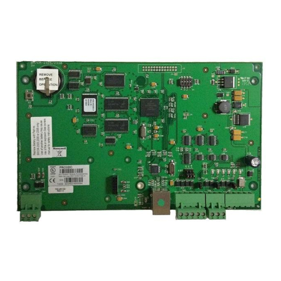
Page 15: Figure 1: Pro3200 Connections, Leds, And Dip Switches
PRO3200 Installation Product Overview Figure 1: PRO3200 Connections, LEDs, and DIP Switches PRO3200 Installation and Configuration Guide, Document 800-15494... -
Page 16: Setting Up The Pro3200 Hardware
Setting Up the PRO3200 Hardware 3 Setting Up the PRO3200 Hardware The PRO3200 processor is configured with 12 jumpers and a set of 4 DIP switches. These jumpers/switches set up the port interface, end of line termination, and operating mode configuration. Refer to the tables below to set the jumpers as required. -
Page 17: Setting The Dip Switches
LED pattern changes to the flashing of LEDs 1 and 4. The panel then reboots by itself. All data in memory is erased except the serial number, MAC address, hardware revision, and OEM code. PRO3200 Installation and Configuration Guide, Document 800-15494... - Page 18 PRO3200 Installation Setting Up the PRO3200 Hardware The PRO3200 DIP switches need to be set twice: 1. Configure the S4-S3-S2-S1 DIP switches to off-off-on-off to set the default TCP/IP address to 192.168.0.251. 2. Apply power to the panel to set the IP address.
-
Page 19: Technical Specifications
18AWG wires. POLARITY for 12 VDC power is important. Make sure the +12 VDC is connected to the Note: terminal labeled +12V and the return is connected to the terminal labeled GND. PRO3200 (PRO32IC) Installation and Configuration Guide, Document 800-15494... -
Page 20: Status Leds
PRO3200 Installation Setting Up the PRO3200 Hardware 3.4 Status LEDs The PRO3200 uses six on-board LEDs to provide status information during its initialization sequence and normal run-time operation. Initialization Table 4 PRO3200 Status LED Combinations During Initialization LED 1 LED 2... -
Page 21: Supplying Power To The Pro3200 Interface
PRO3200 Installation Setting Up the PRO3200 Hardware Run TimeSupplying Power to the PRO3200 Interface Table 5 PRO3200 Status LED Combinations During Run Time Description Off-Line / On-Line and Battery Status Off-Line = 20% On, ON-Line = 80% On Double Flash means the Battery is Low... -
Page 22: Communications Wiring
BR2330, or CR2330 battery should be replaced annually. A replacement battery may be obtained from Honeywell or a local battery retailer. However, the replacement battery must be UL recognized. Battery may explode if mistreated. DO NOT RECHARGE, DISASSEMBLE or DISPOSE... -
Page 23: System Configuration Via Web Interface
PRO3200 Installation System Configuration via Web Interface 4 System Configuration via Web Interface The PRO3200 comes with Access Control Device Server Manager (ACDSM). The ACDSM is a built-in web server, through which you can configure network and other system settings. Notes: •... -
Page 24: Home Page
PRO3200 Installation System Configuration via Web Interface 4.3 Home Page The first screen after the login is the home page which displays all the available configuration links on the left navigation bar: Figure 6: PRO3200 Web Server Home Page www.honeywell.com... -
Page 25: Network Settings
Dynamic IP option because of your network policies or configuration, you must reserve an IP address at the DHCP server for the MAC (Media Access Control) address in the PRO3200 panel. The MAC address is a unique identifier attached to network adapters. Each time the PRO3200 panel requests an IP address, the DHCP server will assign the address that was reserved for it. -
Page 26: Host Port
Primary Host Port and Alternate Host Port: Some of the fields change dynamically depending on the Connection Type selected. Note: IP Server Connection Type Figure 8: PRO3200 Host Port Configuration Screen with IP Server Connection PRO3200 www.honeywell.com... - Page 27 PRO3200 Installation System Configuration via Web Interface 1. From PRO3200 Communication Address drop-down list, select one of the eight (0 to 7) available communication addresses for the PRO3200 board. In the previous panels, this selection was made manually by setting the DIP switches.
-
Page 28: Figure 9: Pro3200 Host Port Configuration Screen With Ip Client Connection
PRO3200 Installation System Configuration via Web Interface IP Client Connection Type Figure 9: PRO3200 Host Port Configuration Screen with IP Client Connection PRO3200 The PRO3200 panel does not currently support an IP Client connection. Note: www.honeywell.com... -
Page 29: Figure 10: Pro3200 Host Port Configuration With Serial Rs-232 Connection
Figure 10: PRO3200 Host Port Configuration with Serial RS-232 Connection PRO3200 1. From the PRO3200 Communication Address drop-down list, select one of the eight (0 to 7) available communication addresses for the PRO3200 board. 2. For the Primary Host Port, make the following selections: a. -
Page 30: Device Information
PRO3200 Installation System Configuration via Web Interface 4.6 Device Information Click the Device Info link on the navigation bar to display the read-only Access Control Device Hardware Information screen: Figure 11: PRO3200 Web Server Device HW Info Screen www.honeywell.com... -
Page 31: User Configuration
4.7 User Configuration Click the Users link on the navigation bar to display the User screen where you can add, edit, and delete user records: Figure 12: PRO3200 Web Server User Info Screen PRO3200 Adding a User Follow these steps: 1. -
Page 32: Restore Default Screen
Click the Restore Default link on the navigation bar to restore the default configuration values for the PRO3200: Figure 13: PRO3200 Web Server Restore Default Screen 1. Click Restore Default to reload the default factory settings for all the configuration variables. -
Page 33: Apply Setting Screen
Figure 14: PRO3200 Web Server Apply Setting Screen Click Apply, Reboot to apply all the configured values and reboot the PRO3200. 4.10 Log Out Click the Log Out link on the navigation bar to log out of the web server. - Page 34 PRO3200 Installation System Configuration via Web Interface www.honeywell.com...
- Page 35 For more information: www.honeywellaccess.com Honeywell Access Systems 135 W. Forest Hill Avenue Oak Creek, WI 53154 414-766-1700 414-766-1798 Fax European Office Boblingerstrasse 17 D-71101 Schonaich Germany 49-7031-637-782 49-7031-637-769 Fax www.honeywell.com Specifications subject to change without notice. © 2013 Honeywell. All rights reserved. 800-15494...
Need help?
Do you have a question about the PRO3200 and is the answer not in the manual?
Questions and answers