
Related Manuals for GESTRA LRR 1-60


Summary of Contents for GESTRA LRR 1-60
- Page 1 Conductivity Controller LRR 1-60 Original Installation & Operating Manual 819692-00 E n g l i s h...
-
Page 2: Table Of Contents
Functional elements and dimensions ......................17 Installing the LRR 1-60 conductivity controller ..................18 Electrical connection safety notes ....................... 18 Wiring diagram of LRR 1-60 conductivity controller .................. 19 Electrical connection ............................ 20 Bus line, cable length and cross-section ....................20 Connecting the 24V DC power supply ...................... - Page 3 Indication of system malfunctions ......................27 What to do in the event of system malfunctions..................28 Taking out of service ............................ 28 Disposal ................................ 28 Returning decontaminated equipment ......................28 EU Declaration of Conformity ........................29 LRR 1-60 - Installation & Operating Manual - 819692-00...
-
Page 4: Content Of This Manual
© Copyright All rights reserved. Any misuse, particularly reproduction and dissemination to third parties, is not permit- ted. The General Terms & Conditions of GESTRA AG apply. Scope of delivery/Product package 1 x Conductivity Controller LRR 1-60 ■ ■... -
Page 5: How To Use This Manual
How to use this Manual This Installation & Operating Manual describes the correct use of the LRR 1-60 conductivity controller. It applies to persons who integrate this equipment in control systems, install, bring into service, operate, maintain and dispose of this equipment. Anyone carrying out the above-mentioned activities must have read this Installation &... -
Page 6: Types Of Warning
Warning of a dangerous situation that may possibly result in death or serious injury. CAUTION Warning of a situation that may result in minor or moderate injury. ATTENTION Warning of a situation that results in damage to property or the environment. LRR 1-60 - Installation & Operating Manual - 819692-00... -
Page 7: Specialist Terms/Abbreviations
When the equipment is back in normal mode, the continuous blowdown valve returns to the control position. An intermittent blowdown pulse is also triggered (if automated intermittent blowdown is enabled and a blowdown interval and blowdown time have been set). LRR 1-60 - Installation & Operating Manual - 819692-00... - Page 8 This type of electrically non-conductive connection makes sure the input and output circuits are electrically isolated from each other. PI controller Controller with proportional (P) and integral (I) control. SELV Safety Extra Low Voltage LRR 1-60 - Installation & Operating Manual - 819692-00...
-
Page 9: Usage For The Intended Purpose
Usage for the intended purpose The LRR 1-60 conductivity controller can be used in conjunction with LRG 16-60, LRG 16-61 and LRG 17- 60 conductivity electrodes as a conductivity controller in pressurised steam and hot-water plants and in condensate and feedwater tanks. The conductivity controller indicates when MAX or MIN conductivity has been reached, opens or closes a continuous blowdown valve and can actuate an intermittent blowdown valve. -
Page 10: Applicable Directives And Standards
Usage for the intended purpose Applicable directives and standards The LRR 1-60 conductivity controller has been tested and approved for use in the scope governed by the following directives and standards: Directives: Directive 2014/35/EU Low Voltage Directive ■ ■ Directive 2014/30/EU EMC Directive ■... -
Page 11: Basic Safety Notes
Check that the system is not carrying live voltage before commencing work. ■ ■ Faulty equipment jeopardises system safety. If the LRR 1-60 conductivity controller does not behave as described on pages 24 to 26, ■ ■ it may be faulty. -
Page 12: Function
Function The LRR 1-60 conductivity controller is a 3-point stepping controller. It periodically evaluates the data telegrams from a conductivity electrode (e.g. LRG 16-60, LRG 16-61 or LRG 17-60). The conductivity controller indicates when MAX or MIN conductivity has been reached, opens or closes a continuous blowdown valve and can actuate an intermittent blowdown valve. -
Page 13: Technical Data
1 x actual value output 4 - 20 mA, e.g. for an actual value display ■ ■ Max. load resistance 500 W ■ ■ Inductive loads must have interference suppression (RC combination) as per the manufacturer's ■ ■ specification LRR 1-60 - Installation & Operating Manual - 819692-00... - Page 14 ■ 2 x 1.5 mm stranded with sleeve ◆ ■ Fastening of body: Mounting clip on support rail TH 35 (to EN 60715) ■ ■ Weight Approx. 0.5 kg ■ ■ LRR 1-60 - Installation & Operating Manual - 819692-00...
-
Page 15: Name Plate/Identification Lrr 1-60
Option CH CL CanBus marking GESTRA AG Manufacturer Disposal Münchener Str. 77 xxxxxxxxxxxx 28215 Bremen information GERMANY Fig. 4 Serial number The date of production is printed on the back of the equipment. LRR 1-60 - Installation & Operating Manual - 819692-00... -
Page 16: Factory Settings
With actuation of an intermittent blowdown valve (MIN relay function = automatic intermittent blowdown) Intermittent blowdown interval: 24 hours ■ ■ Intermittent blowdown time: 3 seconds ■ ■ Number of ■ ■ intermittent blowdown pulses: Pulse interval: 2 seconds ■ ■ LRR 1-60 - Installation & Operating Manual - 819692-00... -
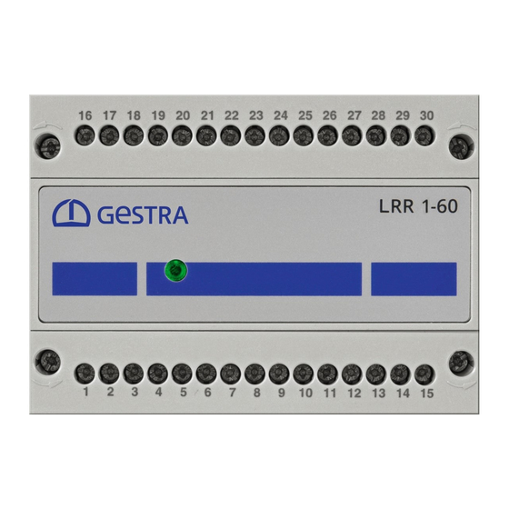
Page 17: Functional Elements And Dimensions
Fastening screws (M3) 4-pole code switch, for setting the controller Equipment settings, group and baud rate see page 23. Front membrane with status LED, see page 24 Housing Support rail TH 35 LRR 1-60 - Installation & Operating Manual - 819692-00... -
Page 18: Installing The Lrr 1-60 Conductivity Controller
Installing the LRR 1-60 conductivity controller The LRR 1-60 conductivity controller snaps onto a TH 35 support rail in the control cabinet. DANGER There is a risk of electric shock during work on electrical systems. Switch off the voltage to the system before you install the equipment. -
Page 19: Wiring Diagram Of Lrr 1-60 Conductivity Controller
CH = CAN High CL = CAN Low Supply voltage S = shield Indication of valve position On-site fuse (potentiometer 0 - 1000 W) M 0.5 A Actual value output Fig. 6 LRR 1-60 - Installation & Operating Manual - 819692-00... -
Page 20: Electrical Connection
■ ■ influences. Connecting the 24V DC power supply The LRR 1-60 conductivity controller is supplied with 24 V DC. ■ ■ A safety power supply unit that delivers a Safety Extra Low Voltage (SELV) must be used to supply the ■... -
Page 21: Wiring Diagram Of Can Bus System
The LRR 1-60 conductivity controller is equipped with an internal terminating resistor. ■ ■ To activate the internal terminating resistor in the LRR 1-60 conductivity controller, insert a bridge between the terminals (“Option” and “CH”). The CAN bus network must not be interrupted during operation! ■... -
Page 22: Changing The Equipment Settings
Check that the system is not carrying live voltage before commencing work. ■ ■ You can change the baud rate and controller group of the conductivity controller LRR 1-60 at any time using code switch D (see Fig. 5) . -
Page 23: Configuring The Controller Group And Baud Rate
Configure the conductivity controller as described in the Installation & Operating Manual of the URB 60 visual display and operating unit. You can find the latest Installation & Operating Manuals for the system components named ■ ■ in Fig. 1 on our website: http://www.gestra.com/documents/brochures.html LRR 1-60 - Installation & Operating Manual - 819692-00... -
Page 24: Bringing Into Service - Start, Operation And Alarm
= power up/green = running/red = malfunction The MIN relay is configured as the MIN alarm on the URB 60 Startup During startup, all the relays of the LRR 1-60 3-point stepping conductivity controller are de-energised and the LED lights up orange. Normal operation During normal operation, when the supply voltage is on and the measured conductivity is within the MIN and MAX switchpoints, the MIN and MAX relays of the controller are energised. -
Page 25: The Min Relay Is Configured For Automatic Intermittent Blowdown On The Urb 60
In the event of a malfunction, the LED lights up red and the MIN/MAX relays become de-energised. The OPEN/CLOSED relays behave as described in the tables on page 27. Faulty equipment jeopardises system safety. If the LRR 1-60 conductivity controller does not behave as described on this page, it may be ■ ■ faulty. -
Page 26: System Malfunctions
Disconnect all poles of the supply cable from the mains and secure so they cannot be ■ ■ switched back on. Check that the system is not carrying live voltage before commencing work. ■ ■ Interrupting the CAN bus during operation triggers an alarm. ■ ■ LRR 1-60 - Installation & Operating Manual - 819692-00... -
Page 27: Indication Of System Malfunctions
System malfunctions Indication of system malfunctions Fig. 10 Multicolour LED (orange/green/red), orange = power up/green = running/red = malfunction Indication of malfunctions in the conductivity controller LRR 1-60 (MIN relay configured as MIN alarm) Relay Type of fault/malfunction CLOSED OPEN... -
Page 28: What To Do In The Event Of System Malfunctions
Check that the equipment is not live. Unscrew and pull off the lower terminal strip, see Fig. 5 A; B Release the slider holder on the base of the equipment, and detach the LRR 1-60 conductivity control- ler from the support rail. -
Page 29: Eu Declaration Of Conformity
EU Declaration of Conformity We hereby declare that the LRR 1-60 conductivity controller conforms to the following European Directives: Directive 2014/35/EU Low Voltage Directive ■ ■ Directive 2014/30/EU EMC Directive ■ ■ Directive 2011/65/EU RoHS Directive ■ ■ Please see our Declaration of Conformity for details on the conformity of our equipment with European Directives. - Page 30 For your notes LRR 1-60 - Installation & Operating Manual - 819692-00...
- Page 31 For your notes LRR 1-60 - Installation & Operating Manual - 819692-00...
- Page 32 You can find our authorised agents around the world at: www.gestra.com GESTRA AG Münchener Straße 77 28215 Bremen Germany Phone +49 421 3503-0 +49 421 3503-393 e-mail info@de.gestra.com www.gestra.com 819692-00/08-2019cm (808944-00) · GESTRA AG · Bremen · Printed in Germany...
Need help?
Do you have a question about the LRR 1-60 and is the answer not in the manual?
Questions and answers