FIOR & GENTZ NEURO TRONIC Instructions For Use For Patients
System knee joint
Hide thumbs
Also See for NEURO TRONIC:
- Manual (157 pages) ,
- Instructions for use manual (42 pages) ,
- Patient information (29 pages)
Table of Contents
Advertisement
Quick Links
Advertisement
Table of Contents

Related Manuals for FIOR & GENTZ NEURO TRONIC


Summary of Contents for FIOR & GENTZ NEURO TRONIC
- Page 1 Instructions for Use for Patients NEURO TRONIC...
-
Page 2: Table Of Contents
Content Page Instructions for Use for PatientsAutomatic Electronic System Knee Joints Safety Instructions 1.1 Classification of the Safety Instructions 1.2 All Instructions for Your Safety 2.1 Intended Use 2.2 Indication 2.3 Contraindication 2.4 Qualification 2.5 Application Knee Joint System 3.1 Joint Functions 3.1.1 Basic Function in Auto Mode 3.1.2... - Page 3 19.3 Electromagnetic Immunity for all Devices and Systems 19.4 Electromagnetic Immunity for Non-Life-Supporting Devices and Systems 19.5 Recommended Safety Distances between Portable and Mobile RF Telecommunication Equipment and the Product NEURO TRONIC for Non-Life-Supporting Devices and Systems 20. Handing Over the Orthosis...
-
Page 4: Instructions For Use For Patientsautomatic Electronic System Knee Joints
Instructions for Use for Patients Automatic Electronic System Knee Joints Instructions for Use for Patients NEURO TRONIC System Knee Joint Dear Patient, You have received an individually produced orthosis with a high quality FIOR & GENTZ automatic electronic system knee joint from your orthotist or a qualified/trained expert. - Page 5 WARNING Jeopardising the Therapy Goal by Not Providing the Necessary Free Movement Check if the system joint moves freely in order to avoid restrictions of the joint function. WARNING Risk of Falling Due to Permanent Higher Load Do not engage in any sports with the orthosis that expose it to excessive strain. If your patient data has changed (e.g.
- Page 6 WARNING Risk of Injury Due to Improper Handling of the Controller or Remote Control Use the controller and the remote control as described in these instructions for use. The orthosis may not be worn while it is charging. The controller is a sensitive electronic device with an integrated lithium-pol- ymer battery.
-
Page 7: Intended Use
NOTICE Damages to Controller and Remote Control Due to Improper Handling Ensure the correct use in order to avoid joint dysfunction. Avoid: - to open the controller and the remote control as well as - using them in areas where radio waves are forbidden (e.g. in planes, hospitals). Ask the responsible staff on-site about using the controller and remote control. -
Page 8: Knee Joint System
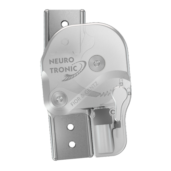
Knee Joint System The knee joint system is equipped with Bluetooth® technology* and consists of the following components (fig. 1): system knee joint controller remote control for the patient including charging cable with adapter and User app Expert app for the orthotist or the qualified/trained expert The system knee joint and the controller are built into your orthosis. -
Page 9: Joint Functions
ET0780 adapter pce. Joint Functions The NEURO TRONIC is a microprocessor-controlled, automatic system knee joint that provides four joint functions: - basic function in delivery status in Auto mode - alternative function in Lock mode - alternative function in Free mode... -
Page 10: Alternative Function In Lock Mode
Initial swing Mid swing Fig. 4 NEURO TRONIC: FASES DE LA MARCHA RELEVANTES PARA LA ARTICULACIÓN If, contrary to expectations, you put weight on the leg with orthosis during the free moving phases, the system joint will not lock. Bloqueada... -
Page 11: The Remote Control
The Remote Control You can select the mode on your orthosis with the remote control. Make sure that you are standing secure- ly when changing the mode of your orthosis. Every time you press a button on the remote control, the LED flashes briefly. -
Page 12: The Controller
The Controller The controller is mounted to your orthosis. It receives commands from the remote control/app, registers your movements and controls the system knee joint. Controller with Integrated Item Description Lithium-Polymer Battery multicolour LED display for battery charging, mode and Bluetooth connection MODE button charging connection... -
Page 13: Connection Between Controller And Remote Control/App
Controlling Two Orthoses If you are wearing two orthoses with a NEURO TRONIC knee joint system, you have the option of connecting the controllers of both orthoses with one or two remote controls. If you activate two remote controls, you can change the modes separately for each controller/orthosis. -
Page 14: Indication Of The Connection With One Controller
Indication of the Connection with one Controller Remote Control Light Signal Meaning colour: yellow, green, red (depending on battery status) The remote control is connected signal duration: with the controller. The command was sent successfully. colour: red - The orthosis is in Sleep mode (see signal duration: paragraph 8.2). -
Page 15: Indication Of The Connection With Two Controllers
Indication of the Connection with two Controllers Remote Control Light Signal Meaning colour: yellow, green, red (depending on battery status) The remote control is connected signal duration: with the controllers. The com- mand was sent successfully to an orthosis. colour: red - The orthoses are in Sleep mode signal duration: (see paragraph 8.2). -
Page 16: Checking The Mode And Battery Status
Checking the Mode and Battery Status Indication of Mode and Battery Status on the Controller You can see the mode and battery status of the controller on the remote control or in the app. Furthermore, the LED battery level indicator displays the following light signals for the battery status: Light Signal Meaning colour: yellow, green, red (depending on battery... -
Page 17: Indication Of The Battery Status For A Connection With One Controller
7.2.1 Indication of the Battery Status for a Connection with one Controller Light Signals for the Remote Control (with Auto Mode Example): Light Signal Signal Colour Remote Control Duration Meaning The battery for the green controller is fully charged. The battery status is low. -
Page 18: Energy Consumption
If two NEURO TRONIC system knee joints are built into your orthosis (bilateral construction), the batteries’ period of use is shortened compared to a unilateral construction (one NEURO TRONIC system knee joint in your orthosis). The following average battery life was determined at room temperature:... -
Page 19: Handling Of The Battery In The Controller
Handling of the Battery in the Controller The controller has a long service life and battery lifespan. Do not try to disassemble the controller as the battery is a fixed part of the controller. Charging the Lithium-Polymer Battery You can charge the battery using the charging cable and power supply unit included in the scope of delivery, via a common household power socket. -
Page 20: Gait Re-Education
10.4 Gait Re-Education In order to be able to use your orthosis optimally, you should make use of a physiotherapeutic gait re-educa- tion. In gait re-education, the following should be specially trained: - walking upright, with the upper body slightly bent forward; - applying as little body weight as possible on walking assistive devices (such as canes, parallel bars or walk- ers) since otherwise the physiological gait can be affected With gait re-education, you become more secure in using your orthosis, your gait pattern improves and you get... -
Page 21: Malfunction Due To External Impact
10.5 Malfunction Due to External Impact The system knee joint is provided with electronic components that react sensitively to very strong shocks. This can cause the system joint not to remain unlocked during the swing phase but to lock. The orthosis should then work in the previously set mode again. -
Page 22: Dirt Removal From The System Joint
11.1 Dirt Removal from the System Joint Remove dirt from the system joint on a regular basis. Use a dry cloth and clean the system joint only superfi- cially. Then, remove visible dust and lint from the mechanics by using tweezers. Check the orthosis in straight and flexed position. -
Page 23: Controller
13.3 Controller Problem Cause Further Action Charge the battery. When the MODE button is pressed, The battery is not charged. If the problem remains, contact your the LEDs do not light up. orthotist or a qualified/trained expert. Within 30 seconds of pressing the MODE button, establish a connection between the User app and controller No devices are found during con-... - Page 24 Storage ambient temperature +5°C – +40°C, no exposure to direct sunlight relative air humidity max. 95%, non-condensing air humidity air pressure 1060mbar – 700mbar Data Transmission remote technology bluetooth low energy working range min. 2m frequency range 2402MHz – 2480MHz modulation GFSK data rate (OTA)
-
Page 25: Signs And Symbols
16. Signs and Symbols CE labelling according to Regulation (EC) 2017/745 for medical devices medical device catalogue number Do not dispose of electronic devices with household waste. Dispose of the device and accessories at official delivery points for electronic devices. manufacturer batch code protect from heat... - Page 26 single patient – multiple uses IP44 protection from the ingress of solid foreign bodies (diameter ≥ 1.0 mm) and from splashing water on all sides Unique Device Identifier – product identification number Remote Control Type Plate ET3840-P IP44 FIOR & GENTZ GmbH www.fior-gentz.de ET3840-P IP44 FIOR &...
-
Page 27: Ce Conformity
17. CE Conformity We declare that our medical devices as well as our accessories for medical devices are in conformity with the requirements of Regulation (EU) 2017/745. Therefore, the FIOR & GENTZ products bear the CE marking. The product satisfies the requirements of the RoHS Directive 2011/65/EU of the European Parliament and of the Council of 8 June 2011, for limiting the use of specific hazardous substances in electrical and electronic equipment. -
Page 28: Electromagnetic Compatibility
Usage Instructions and Manufacturer’s Declaration – Electromagnetic Emissions The product NEURO TRONIC is designed for operation in an electromagnetic environment as specified below. The customer or user of the product NEURO TRONIC must ensure that it is operated exclusively in such an environment. -
Page 29: Electromagnetic Immunity For All Devices And Systems
Usage Instructions and Manufacturer’s Declaration – Electromagnetic Immunity The product NEURO TRONIC is designed for operation in an electromagnetic environment as specified below. The customer or user of the product NEURO TRONIC must ensure that it is operated exclusively in such an environment. -
Page 30: Electromagnetic Immunity For Non-Life-Supporting Devices And Systems
Usage Instructions and Manufacturer’s Declaration – Electromagnetic Immunity The product NEURO TRONIC is designed for operation in an electromagnetic environment as specified below. The customer or user of the product NEURO TRONIC must ensure that it is operated exclusively in such an environment. -
Page 31: Recommended Safety Distances Between Portable And Mobile Rf Telecommunication Equipment And The Product Neuro Tronic For Non-Life-Supporting Devices And Systems
The product NEURO TRONIC is designed for operation in an electromagnetic environment where RF inter- ference is monitored. The customer or user of the product NEURO TRONIC can help prevent electromagnetic interference by complying with the minimum distances between portable and mobile RF communication equipment (transmitters) and the product NEURO TRONIC, as specified below according to the maximum output of the communication equipment. -
Page 32: Handing Over The Orthosis
Handing Over the Orthosis When handing over the orthosis to the patient, parents or care team by the orthotist or qualified/trained expert, they also received the instructions for use for patients as well as the orthosis service passport. The functions and handling of the orthosis were explained in detail by means of these instructions for use. Enter the next maintenance appointment in the orthosis service passport. - Page 33 ORTHOSIS SERVICE PASSPORT Have you not yet received an orthosis service passport? Ask your orthotist or a qualified/trained expert! • • • • Gesellschaft für Entwicklung und Vertrieb Dorette-von-Stern-Straße 5 +49 4131 24445-0 info@fior-gentz.de von orthopädietechnischen Systemen mbH 21337 Lüneburg (Germany) +49 4131 24445-57 www.fior-gentz.com...