Table of Contents
Advertisement
Quick Links
Advertisement
Table of Contents

Related Manuals for KNF UFK 1.1100 EX


Summary of Contents for KNF UFK 1.1100 EX
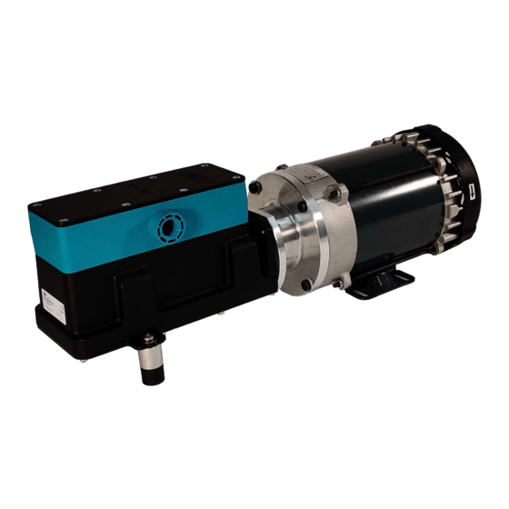
- Page 1 UFK 1.1100 EX INSTALLATION INSTRUCTIONS DIAPHRAGM PUMP KNF Neuberger, Inc 2 Black Forest Rd Trenton NJ 08691-1810 609-890-8600 www.knfusa.com Ident#337361/337364 Revision (03/22) Before operating the pump and the accessories, please read the Installation Instructions and safety precau- tions.
-
Page 2: Table Of Contents
Cleaning Preparing for dismantling Dismantling the pump head Assembling the pump head Overpressure protection .27 ..........18 Dismantling and cleaning Assembling Rectifying transfer problems ..........20 Spare parts ................21 Returning the pump ............... 22 KNF Flodos UFK1.1100Ex O&M-Rev2 Original-Betriebsanleitung... -
Page 3: General
Installation Instructions UFK 1.1100 Ex 1 General 1.1 Information about the instructions Content The Installation Instructions describe the requirements for installing the product correctly and safely into the complete machine. Storage location These Installation Instructions are a part of the product. The safety- relevant information should be taken over for the documentation of the complete machine. -
Page 4: Disclaimer
The listed documents must also be observed. The valid versions are available at www.knf.com/en/us/service/downloads. Data sheet 3D model The following must also be observed: Local T&Cs Sales documents and agreement between KNF and the cus- tomer Drive specification KNF Flodos UFK1.1100Ex O&M-Rev2... -
Page 5: Safety
Installation Instructions UFK 1.1100 Ex 2 Safety 2.1 Intended use The pump is intended solely for the following uses: Transferring liquids and gases For operation in accordance with the operating parameters specified in the technical data of the supporting documents 2.2 Reasonably foreseeable misuse... - Page 6 Installation Instructions UFK 1.1100 Ex Danger of injuries and damage to property due to leaks at the interfaces to the pump head Poisoning and chemical burns or unintended reactions caused by leaking dangerous substances Wear personal protective equipment. Connect the pump correctly.
-
Page 7: Customer Service And Repairs
Keep flammable materials away from the direct vicinity of the pump and piping. 2.5 Customer service and repairs All repairs to the pumps must be carried out by the responsible KNF service team. Use only genuine parts from KNF for servicing work. KNF, Inc. UFK1.1100 Ex.docx... -
Page 8: Installation Location
Installation Instructions UFK 1.1100 Ex 3 Installation WARNING Danger from incorrect installation Injuries or damage to property from leaking media After installation, check the system for leaks with a safe medium. Observe the requirements for intended use. Take precautions in the design of the end device so that leaking liquids cannot come into contact with live compo- nents. -
Page 9: Connecting The Fluid System
Installation Instructions UFK 1.1100 Ex 3.3 Connecting the fluid system Use suitable means to check the fluid connection for leaks. For more information regarding dimensions, please refer to the data sheet. 3.4 Electrical connection For terminal assignment, output data, and control requirements, please refer to the data sheet. - Page 10 Installation Instructions UFK 1.1100 Ex Fig. 2: 230V Connection KNF Flodos UFK1.1100Ex O&M-Rev2...
-
Page 11: Initial Start-Up
Installation Instructions UFK 1.1100 Ex 4 Initial start-up The product must not be started up until it has been ensured that the machine in which the product is to be installed meets the requirements of the Machinery Directive 2006/42/EC, if applicable. - Page 12 Installation Instructions UFK 1.1100 Ex CAUTION Danger from hot surfaces The pump becomes hot during operation. Burns from hot surfaces or injuries from uncontrolled movements are possible. Do not touch the pump while it is operating. Ensure a sufficient supply of cool air and keep a safe dis- tance between the pump and neighboring components.
-
Page 13: Maintenance
Installation Instructions UFK 1.1100 Ex 5 Maintenance Ask your KNF representative about the availability of spare parts for this product. Use only genuine parts from KNF for servicing work. 5.1 Cleaning WARNING Danger due to dangerous substances in the pump Depending on the medium transferred, chemical burns or poison- ing is possible. -
Page 14: Preparing For Dismantling
Installation Instructions UFK 1.1100 Ex 5.2 Preparing for dismantling 1. Rinse the pump with a suitable neutralizing liquid and make sure that there are no dangerous substances left in the pump (see warnings above). 2. Pump the unit empty. 3. Disconnect electrical connections. -
Page 15: Dismantling The Pump Head
Installation Instructions UFK 1.1100 Ex 5.3 Dismantling the pump head Undo the eight head screws (1) and remove the complete head from the pump housing. Remove the head plate (2) from the connecting plate (6). Remove the resonating diaphragm (5), both O-rings (4) and resonating diaphragm support (3) from the head plate (2). -
Page 16: Assembling The Pump Head
Installation Instructions UFK 1.1100 Ex 5.4 Assembling the pump head Insert the three insert rings (11) in the pump housing; see Figure 3. For easier installation of the diaphragms (10), turn the connect- ing rod to top dead center, beginning with head I. Tighten the diaphragms well (10) by hand. - Page 17 Installation Instructions UFK 1.1100 Ex CAUTION Caution, escaping liquid After assembly, the pump may not be leak-tight due to incorrect assembly, damaged or soiled seal faces, or other reasons. Run the pump for several minutes with a harmless medium at maximum operating pressure.
-
Page 18: Overpressure Protection .27
Installation Instructions UFK 1.1100 Ex 6 Overpressure protection .27 Overpressure protection is provided as standard on this HazLoc model. 6.1 Dismantling and cleaning To prepare for dismantling, refer to Section 5.2. Tools Tools Allen key size 4mm Torx screwdriver T10 Table 2 1. - Page 19 Installation Instructions UFK 1.1100 Ex CAUTION Caution, escaping liquid After assembly, the overpressure protection may not be leak-tight due to incorrect assembly, damaged or soiled seal faces, or other reasons. Run the pump for several minutes with a harmless medium at maximum operating pressure.
-
Page 20: Rectifying Transfer Problems
Damage to the valve O- Leak on pump head Replace the O-rings. rings Diaphragm damaged Replace the diaphragm. Resonating diaphragm Replace resonating diaphragm. damaged If the malfunction cannot be rectified, contact your local KNF representative (www.knf.com). KNF Flodos UFK1.1100Ex O&M-Rev2... -
Page 21: Spare Parts
Installation Instructions UFK 1.1100 Ex 8 Spare parts Spare parts kit, small Material Bestell-Nr. Stück im Kit Stück im Kit Pos Name pieces in set pieces in set material order no. Kit klein KP 177998 kit small KP Kit klein KT... -
Page 22: Returning The Pump
Installation Instructions UFK 1.1100 Ex 9 Returning the pump KNF will accept the pump for repair only under the condition that the customer provides a certificate of the pumped medium and cleaning of the pump. For this purpose, please follow the instruc- tions on www.knf.com/repairs. - Page 23 www.knf.com...
- Page 24 ! " # $ %& Phone: (715) 675 3311 +++, Form 5554E...
- Page 25 (% '' $* ;' = %& ( $ %& $D( /( ? ( = %& ( (%$/ % (%$/ % 0 1 , 2 0 - 3 (% ; !,!,# !,!,! <, (% '' $ 9 5 ; $ % $ $ (; ( 7 ' %.
- Page 26 @,<,< @,#,! @,<,# @,#,@ @,<,! @,#, @,#,< @,!,< @,#,# @,!,# EEEEEEEEEEEEEEEEEEEEEEEEEEEEEEEEEEEEEEEEEEEEEEEEEEEEEEEEEEEEEEEEEEEEEEEEEEEEEEEEEEEEEEEEEEEEEEEEEEEEEEEEEEEEEEEEEEEEEEEEE motor is suitable for use on Pulse Width Modulated (PWM) type VFD power. In addition, the nameplate must be marked with the inverter rating; for example, “2:1 CT”, “2 to 1 Constant Torque”, etc. <, $ (;...
- Page 27 motors must meet a #,!,< $ 6 '/7$ Bearings are grease packed minimum distance of ½ the shaft height between the fan guard at the factory; relubrication upon receipt of motor or while in storage grill openings and the nearest obstruction. is not necessary.
- Page 28 mounting a rigid base (footed) motor vertically is the responsibility of !,!,# /;' 6* Use flexible couplings if possible. the installer. For applications that apply radial, axial or moment loading on the motor shaft see section 3.3.3. = $% ' (& % ? 5 * Most standard horizontal motors thru 449 Fr.
- Page 29 < !,!,@,@ Belt tensioning by feel is % acceptable. Tensioning by "feel" can be very misleading, and can damage motor and equipment. It is normal for V belts to squeal initially when line starting a motor. In general, belt tensions should be kept as loose as possible while still transmitting the required torque without slipping.
- Page 30 <# < Avg. Avg. Avg. Sheave Deflected Sheave Deflected Sheave Deflected Dia (in) Belt Force Dia (in) Belt Force Dia (in) Belt Force & Type Belts (lbs) Type Belts (lbs) Type Belts (lbs) 0.75 11.6 14.6 14.1 13.3 10.0 14.5 14.3 10.0 16.0...
- Page 31 to Table 3 5 values. Definite purpose VFD motors may * When thermal protection is provided, one of accommodate longer cable lengths. For additional the following will be stamped on the nameplate: information contact motor manufacturer. <, O%& $ ''. ;$ % % ?”...
- Page 32 & 3 * The gap between mating surfaces with the machined terminal box MUST BE LESS THAN 0.002 inches. This gap must be checked with a feeler gage along the entire perimeter. If there is ' & G $?( visible damage to the mating surfaces, or if the gap between these Before proceeding read Section 1 1 on Electrical Safety.
- Page 33 Do not start more than twice in succession under full load. Repeated starts and/or jogs of induction motors can cause overheating and immediate failure. Contact the motor manufacturer if it is necessary to repeatedly start or jog the motor. ( > $ % % 6 ; $%( & G $? Before proceeding read Section 1 2 on Mechanical Safety.
- Page 34 < Q ): Dow Corning DC44 or equivalent, a special high temperature grease is For RTD settings see Table 3 7. required. Note that Dow Corning DC44 grease does not mix with other grease types. @,#,# ; $ % 6 % ;...
- Page 35 <, Table 4 1 list 10,000 hours for standard conditions. Table 4 2 classifies severity of service as “Severe” with a multiplier of 0.5. @,#,@ '/7$ ?/$ * Table 4 3 lists a multiplier value of 0.5 for “Vertical” + - $ 4 4 ;...
- Page 36 @,!,# * ' 8 0 (1) Check power supply fuses (2) Match motor lead wiring to nameplate connection Supply voltage is too low or is severely unbalanced (one diagram and supply voltage (3) Ensure that steady state supply voltage at motor phase is low or missing).
- Page 37 Motor is started too frequently See section 3.4.5.3 (1) Ensure that steady state supply voltage at motor terminals is within limits (see Supply voltage too low, too high, or unbalanced section 3.4.1.3) Correct as needed (2) Reconnect motor per input voltage (3) Obtain correct motor to match power supply.
- Page 38 Input voltage exceeds limit Verify that voltage to the motor terminals is within limits (see section 3.4.1.3). Power surge to motor (caused by lightning strike or other If a common problem, install surge protector. high transient voltage).
Need help?
Do you have a question about the UFK 1.1100 EX and is the answer not in the manual?
Questions and answers