KNF OEM Original Operating And Installation Instructions
Diaphragm pump
Hide thumbs
Also See for OEM:
Table of Contents
Advertisement
Quick Links
Advertisement
Table of Contents

Subscribe to Our Youtube Channel
Related Manuals for KNF OEM


Summary of Contents for KNF OEM
- Page 1 KNF 339865-336436 01/23 N952KNDC-B TRANSLATION OF ORIGINAL OPERATING AND INSTALLATION INSTRUCTION ENGLISH DIAPHRAGM PUMP Notice! Before operating the pump and accessories, read and observe the operat- ing and installation instructions as well as the safety information!
-
Page 2: Table Of Contents
Table of contents 1 About this document ................ 4 1.1 Using the operating and installation instructions...... 4 1.2 Exclusion of liability............... 4 1.3 Symbols and markings.............. 5 2 Safety .................... 7 2.1 Personnel and target group ............ 7 2.2 Responsibility of the operator ............ 8 2.3 Working in a safety conscious manner ......... - Page 3 9.1 Spare parts ................. 50 9.2 Accessories................. 50 9.3 Motor accessories............... 51 10 Troubleshooting .................. 52 11 Returns.................... 56...
-
Page 4: About This Document
The manufacturer assumes no liability for damages and mal- functions resulting from impermissible spare parts and acces- sories. Translation of Original Operating and Installation Instruction, KNF 339865-336436 01/23... -
Page 5: Symbols And Markings
An activity to be carried out is specified here (a step). 1. The first step of an activity to be carried out is specified here. Other sequentially numbered steps follow. This symbol indicates important information. Translation of Original Operating and Installation Instruction, KNF 339865-336436 01/23... - Page 6 Warning of hot surface Warning of electrical voltage Warning of poisonous substances Warning of hand injuries through crushing Observe the operating instructions General mandatory sign Wear hearing protection Tab.2: Explanation of pictograms Translation of Original Operating and Installation Instruction, KNF 339865-336436 01/23...
-
Page 7: Safety
Tab.3: Target group Who-does-what Lifecycle phase User Specialized per- matrix sonnel Transport Mounting Connection Commissioning Operation Servicing Troubleshooting Disposal Tab.4: Who-does-what matrix Translation of Original Operating and Installation Instruction, KNF 339865-336436 01/23... -
Page 8: Responsibility Of The Operator
Make sure that an EMC-compliant installation of the pump is ensured at all times to prevent the occurrence of dangerous situations. Translation of Original Operating and Installation Instruction, KNF 339865-336436 01/23... -
Page 9: Operating Conditions
Make sure that a dangerous situation cannot arise as a result. When pumping hazardous media, observe the safety regula- tions for the handling of said media. Translation of Original Operating and Installation Instruction, KNF 339865-336436 01/23... -
Page 10: Use
Where applicable, also take into account external energy sources (such as radiated heat sources) that could addition- ally heat the medium. In case of doubt, contact KNF Customer Service. 2.6 Use 2.6.1 Proper use The pumps are intended exclusively for transferring gases and vapors. -
Page 11: Directives And Standards
§ Directive 2011/65/EU on the restriction of the use of cer- tain hazardous substances in electrical and electronic equipment (Annex II changed by delegated Directive (EU) 2015/863 of the Commission) Translation of Original Operating and Installation Instruction, KNF 339865-336436 01/23... -
Page 12: Customer Service And Repair
Alternatively, KNF products (old devices) may also be returned to KNF for a fee (see chapter 11 Re- turns [} 56]). Translation of Original Operating and Installation Instruction, KNF... -
Page 13: Technical Data
[bar rel] Ultimate vacuum [mbar abs.] ≤ 1.5 Flow rate at atm. pressure [l/ min]* Tab.6: *Liters in the standard state (based on ISO 8778 and ISO 21360-1/2) (1013 mbar) Translation of Original Operating and Installation Instruction, KNF 339865-336436 01/23... - Page 14 Low logic level 0…0.4 V Max. cable length ≤ 3m Tab.8: Maximum electrical values Pneumatic connections Pneumatic connections Value Inlet Thread size G1/8* Outlet Thread size G1/8* Tab.9: *Acc. to ISO 228 Translation of Original Operating and Installation Instruction, KNF 339865-336436 01/23...
- Page 15 50% at 40 °C (non-condens- ing). Maximum installation altitude 2000 [m above sea level] Dimensions See Fig. 3, Chapter 6.1 In- stalling the pump [} 20] Degree of contamination Tab.10: Weight Parameter Value Weight [kg] Translation of Original Operating and Installation Instruction, KNF 339865-336436 01/23...
-
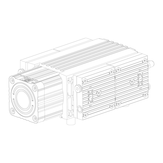
Page 16: Product Description
Product description Diaphragm pump N952KNDC-B 4 Product description Design 1 Outlet 2 Motor 3 Inlet Fig.1: Diaphragm pump N952KNDC-B Translation of Original Operating and Installation Instruction, KNF 339865-336436 01/23... - Page 17 (2). In the upwards stroke, the diaphragm presses the medium out of the pump head via the outlet valve (1). The transfer chamber (3) is separated from the pump drive by the di- aphragm. Translation of Original Operating and Installation Instruction, KNF 339865-336436 01/23...
-
Page 18: Transport
à Store the original packaging of the pump (e.g. for later storage). à Inspect the pump for transport damage after receiving it. à Document any transport damage in writing. Translation of Original Operating and Installation Instruction, KNF 339865-336436 01/23... - Page 19 Permissible humidity (non- 30 to 85 condensing) [%] Tab.11: Transport parameter and storage parameter Prior to commissioning, make sure that the pump has reached the ambient temperature (3 Technical data [} 13]). NOTICE Translation of Original Operating and Installation Instruction, KNF 339865-336436 01/23...
-
Page 20: Installation And Connection
Store the pump at the installation site to allow it to adapt to the ambient temperature before installation (condensa- tion must not be allowed to form). à Mounting dimen- For mounting dimensions, see the following figures: sions Translation of Original Operating and Installation Instruction, KNF 339865-336436 01/23... - Page 21 Make sure that the installation location is dry and that the tion pump is protected from rain, spray water, splash water, dripping water and other contaminants. à Make sure that the installation location allows access for periodic maintenance and inspection. Translation of Original Operating and Installation Instruction, KNF 339865-336436 01/23...
-
Page 22: Electrical Connection
If the drives are not operated in a SELV circuit, this may result in injuries due to electrical shocks. CAUTION à The drives may only be operated in an SELV circuit. Translation of Original Operating and Installation Instruction, KNF 339865-336436 01/23... - Page 23 Refer to the pump type plate for the rated current draw. 2. Connect the positive and negative terminals. Ensure the correct polarity: Red connection cable: + Black connection cable: - Translation of Original Operating and Installation Instruction, KNF 339865-336436 01/23...
-
Page 24: Pneumatic Connection
2. Connect the suction line and the pressure line (for mount- ing dimensions, see Chapter 3 Technical data [} 13]). 3. Lay the suction line and pressure line with a descent so that no condensate can run into the pump. Translation of Original Operating and Installation Instruction, KNF 339865-336436 01/23... -
Page 25: Operation
Ensure the proper use of the pumps (See Chapter Proper use). à Eliminate the possibility of improper use of the pumps (see Chapter Improper use). à Observe the safety instructions (Chapter Safety). Translation of Original Operating and Installation Instruction, KNF 339865-336436 01/23... - Page 26 Further information is available from KNF Customer Service (contact data: see www.knf.com). Translation of Original Operating and Installation Instruction, KNF 339865-336436 01/23...
-
Page 27: Information On Switching The Pump On And Off
à Install an overload protector (see Chapter 6.2 Elec- trical connection [} 22]). à Ensure that normal atmospheric pressure is present in the lines when switching on. Translation of Original Operating and Installation Instruction, KNF 339865-336436 01/23... -
Page 28: Supply Connector
à Inspecting the Inspect the pump periodically for external damage or leak- pump age. 7.3 Supply connector Fig.4: Supply connector Translation of Original Operating and Installation Instruction, KNF 339865-336436 01/23... -
Page 29: Signal Connector
Tab.13: Pin assignment for supply connector 7.4 Signal connector Designation Manufacturer Type (manufac- turer) Connector housing Amphenol 5031491000 Crimp contact Amphenol 5025790000 Cable AWG 24, ≥105°C Cable length ≤3m Tab.14: Signal connector Fig.5: Signal connector Translation of Original Operating and Installation Instruction, KNF 339865-336436 01/23... - Page 30 If no supply voltage is present, the inputs must be potential- free! Tab.15: Assignment of control cable connection Color assignment - KNF standard control cable ID: 322551 GND potential internally connected ³ All digital signals are LVTTL (3.3V); the digital inputs are TTL (5V) compatible.
-
Page 31: Speed Specification
Changing the minimum and maximum values for control voltage in the range from 0…5 V, à Behavior of the pump when control voltage falls below the minimum value: à Pump stops or Translation of Original Operating and Installation Instruction, KNF 339865-336436 01/23... - Page 32 013). The underlined expressions are not characters but rather symbols. The symbols are explained in Tab. 18 [} 34]. There must be a pause of 25 ms between each UART com- mand and the next command. Translation of Original Operating and Installation Instruction, KNF 339865-336436 01/23...
- Page 33 Maximum Readout of the pa- nh ; E speed setpoint rameters for maxi- mum speed Firmware ver- Readout of firmware V ; E sion number version Tab.17: UART protocol Translation of Original Operating and Installation Instruction, KNF 339865-336436 01/23...
- Page 34 This speed must be agreed with KNF in advance and must lie within the minimum and maxi- mum speed range specific to the product. Setpoint speed Setting of the pump speed within the maximum and minimum speed limits.
-
Page 35: Extended Parameterization And Functions Of The Pump
"Start RPM" parameter. By default, Start RPM = 0. However, at the customer's request this value can be set by KNF to a value between the minimum and maximum speed of the cor- responding pump. - Page 36 (from low to high) is measured at the "Remote ON/OFF" input ( Tab. 15 [} 30]/Pin 7). The pump is switched off at a falling edge. Translation of Original Operating and Installation Instruction, KNF 339865-336436 01/23...
- Page 37 The pump ignores the "Remote ON/OFF" signal. The pump rameter: LOCAL can be stopped by allowing the analog control voltage to fall below its minimum value. NOTICE! The optional "Remote RESET" function is dis- abled for this setting. Translation of Original Operating and Installation Instruction, KNF 339865-336436 01/23...
-
Page 38: Error Management
If the setpoint is set digitally via UART, errors can be acknowl- edged directly with the command on the interface. For this, the command "dB" must be sent. Then, all errors that oc- curred are acknowledged. Translation of Original Operating and Installation Instruction, KNF 339865-336436 01/23... -
Page 39: Servicing
à Periodically check for no- ticeable changes to noises and vibrations. à Gas connections Perform periodic inspec- tions for external damage or leakage. Tab.20: Translation of Original Operating and Installation Instruction, KNF 339865-336436 01/23... -
Page 40: Cleaning
8.2.1 Flushing the pump When transferring dangerous and environmentally hazardous media, KNF recommends flushing the pump with air at atmo- spheric pressure for a few minutes prior to switch-off (if nec- essary for safety reasons: with an inert gas) to extend the ser- vice life of the diaphragm. -
Page 41: Replacing The Diaphragm And Valve Plates
Heads 1 and 2: Valves Heads 3 and 4: Valves Only heads 1 and O-ring (Ø 24 x 2) Tab.21: *According to spare parts list, Chapter 9.1 Spare parts 50] **see Fig. 10 Translation of Original Operating and Installation Instruction, KNF 339865-336436 01/23... - Page 42 CAUTION Allow the pump to cool after oper- ation. Disassembling the pump head 1. Disconnect the connection tubing (2/Fig. 8) by pressing and holding down the release ring (1/Fig. 8). Translation of Original Operating and Installation Instruction, KNF 339865-336436 01/23...
- Page 43 Mark the head plate, intermediate plate and compressor housing with four continuous lines using a felt tip pen (M). Marking the various heads helps to avoid incorrect as- sembly later. Translation of Original Operating and Installation Instruction, KNF 339865-336436 01/23...
- Page 44 Diaphragm pump N952KNDC-B Fig.9: Marking of the pump 7. Loosen the outer 8 fastening screws (7/Fig. 10) of the heads (1 and 2) and remove the heads (1 and 2). Translation of Original Operating and Installation Instruction, KNF 339865-336436 01/23...
- Page 45 Servicing Diaphragm pump N952KNDC-B Fig.10: Exploded view 8. Pull heads 1 (I/Fig. 11) and 2 (II/Fig. 11) apart and remove the O-rings (10/Fig. 11) und (13/Fig. 11). Translation of Original Operating and Installation Instruction, KNF 339865-336436 01/23...
- Page 46 10. Remove the head plate from the intermediate plate (2Fig. 12). Fig.12: Exploded view of the pump head Changing the valve plates and fitting the intermediate plate 1. Remove the valves (4/Fig. 12) from the intermediate plates (2/Fig. 12). Translation of Original Operating and Installation Instruction, KNF 339865-336436 01/23...
- Page 47 (12/Fig. 14) as removed. Translation of Original Operating and Installation Instruction, KNF 339865-336436 01/23...
- Page 48 3 and 4 (III and IIII/ Fig. 9). Fitting the connection 1. Push the connection tubing (2/Fig. 8) into the fitting as far as it will go. Translation of Original Operating and Installation Instruction, KNF 339865-336436 01/23...
- Page 49 1. Reconnect the suction and pressure line to the pump. 2. Connect the pump to the power supply. If you have questions with regard to maintenance, please contact your KNF Customer Service (for contact data, visit www.knf.com). To ensure the required gas tightness of the pump follow- ing servicing, a leak test is to be performed.
-
Page 50: Spare Parts And Accessories
Spare parts and accessories Diaphragm pump N952KNDC-B 9 Spare parts and accessories To order spare parts and accessories, please contact your KNF sales partner or KNF Customer Service (con- tact data: see www.knf.com). 9.1 Spare parts Parts Item num- Number per... -
Page 51: Motor Accessories
300 mm Signal cable 322551 with pre-assembled connector and length of 300 mm RS232 adapter cable Upon request with 9-pin S-sub connector UART-USB transceiver cable Upon request Translation of Original Operating and Installation Instruction, KNF 339865-336436 01/23... -
Page 52: Troubleshooting
à Check and ensure that no voltage is present. à Allow the pump to cool before troubleshooting. à Check the pump (see following tables). Translation of Original Operating and Installation Instruction, KNF 339865-336436 01/23... - Page 53 The applied voltage must not exceed the value specified in Chapter 6.2 Electrical connection [} 22]. à Diaphragm and valves Replace diaphragm and valves (see Chapter 8 Ser- are worn or defective. vicing [} 39]). Tab.25: Translation of Original Operating and Installation Instruction, KNF 339865-336436 01/23...
- Page 54 Clean the head components. à Operating diaphragm Shut down the pump immediately. broken à Diaphragm and valves Replace diaphragm and valves (see Chapter 8 Ser- are worn or defective. vicing [} 39]). Tab.26: Translation of Original Operating and Installation Instruction, KNF 339865-336436 01/23...
- Page 55 Fault cannot be rectified If you are unable to identify any of the specified causes, send the pump to KNF Service (contact data: see www.knf.com). 1. Flush the pump with air for a few minutes (if necessary for safety reasons: with an inert gas) at atmospheric pressure in order to remove hazardous or aggressive gases from the pump head (see Chapter 8.2.1 Flushing the pump...
-
Page 56: Returns
If necessary, request original packaging for a fee. Returns KNF shall undertake to repair the pump only under the condi- tion that the customer presents a certificate regarding the medium that is pumped and the cleaning of the pump. In this case too, old devices can be returned. - Page 60 KNF Neuberger GmbH Alter Weg 3 79112 Freiburg Germany Tel. +49 (0)7664/5909-0 E-mail: info.de@knf.com www.knf.com KNF worldwide You can find our local KNF partners at: www.knf.com...
Need help?
Do you have a question about the OEM and is the answer not in the manual?
Questions and answers