Table of Contents
Advertisement
Quick Links
Operating and Installation Instructions
Diaphragm Vacuum Pumps
and Compressors
Type Ranges:
UN035ANI EX
UN035SNI EX
UN035ATI EX
UN035SN.9I EX
UN035AVI EX
UN035STI EX
UN035TNI EX
UN035ST.9I EX
UN035TTI EX
UN035SVI EX
UN035TVI EX
UN035SV.9I EX
KNF Neuberger, Inc
2 Black Forest Rd
Trenton, NJ 08691-1810
Phone: 609-890-8600
Fax:
609-890-8323
www.knfusa.com
Ident#218837-218839
Revision (07/18)
UN035.1.2ANI EX
UN035.1.2AN.9I EX
UN035.1.2ATI EX
UN035.1.2AT.9I EX
UN035.1.2AVI EX
UN035.1.2TNI EX
UN035.1.2TTI EX
UN035.1.2TVI EX
Contents
1. About this document ................................................................. 2
2. Use ........................................................................................... 3
3. Safety ....................................................................................... 4
4. Technical Data.......................................................................... 5
5. Design and Function ................................................................ 8
6. Installation and connection ..................................................... 11
7. Operation ................................................................................ 16
8. Servicing ................................................................................. 18
9. Troubleshooting ...................................................................... 27
10. Spare parts and accessories .................................................. 29
11. Product Return ....................................................................... 30
UN035.1.2STI EX
UN035.3ANI EX
UN035.1.2ST.9I EX
UN035.3AN.9I EX
UN035.1.2SVI EX
UN035.3ATI EX
UN035.1.2SV.9I EX
UN035.3AVI EX
UN035.3STI EX
UN035.3ST.9I EX
UN035.3SVI EX
UN035.3SV.9I EX
UN035.3TTI EX
UN035.3TVI EX
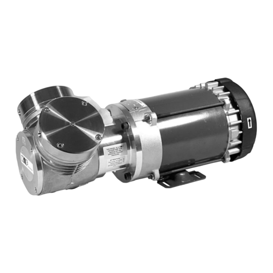
Fig. 1: UN035.3STI EX
Page
Advertisement
Table of Contents

Related Manuals for KNF UN035ANI EX


Summary of Contents for KNF UN035ANI EX
-
Page 1: Table Of Contents
Operating and Installation Instructions Diaphragm Vacuum Pumps and Compressors Type Ranges: UN035ANI EX UN035SNI EX UN035.1.2ANI EX UN035.1.2STI EX UN035.3ANI EX UN035ATI EX UN035SN.9I EX UN035.1.2AN.9I EX UN035.1.2ST.9I EX UN035.3AN.9I EX UN035AVI EX UN035STI EX UN035.1.2ATI EX UN035.1.2SVI EX UN035.3ATI EX UN035TNI EX UN035ST.9I EX... -
Page 2: About This Document
About this document Diaphragm Pump UN035_I EX About this document 1.1. Using the Operating and Installation Instruc- tions The operating and installation instructions are part of the pump. Pass on the Operating and Installation Instructions to the next owner. Project pumps Customer-specific project pumps (pump models which begin with “PU”... -
Page 3: Use
Diaphragm Pumps UN035_I EX 2.1. Proper use The pumps are exclusively intended for transferring gases and vapors. Owner's responsibility Operating parameters and Only install and operate the pumps under the operating parameters conditions and conditions described in Chapter 4, Technical data. Requirements for Before using a medium, check whether the medium can be trans- transferred medium... -
Page 4: Safety
This especially applies to parts contaminated with toxic substances. Certifications Motors are UL listed and CSA certified. Repairs should only be carried out by the KNF Factory responsible. Customer service and repairs Use only genuine parts from KNF for servicing work. -
Page 5: Technical Data
Diaphragm Pumps UN035_I EX Technical Data Technical Data Pump materials Pump type Material* Pump head Diaphragm Valve Gasket Aluminium Stainless Steel UN035_AN_I EX Aluminium PTFE-coated Stainless Steel UN035_AT_I EX Aluminium Stainless Steel UN035_AV_I EX Stainless Steel UN035_SN_I EX Stainless Steel PTFE-coated PTFE UN035_ST_I EX... - Page 6 Technical Data Diaphragm Pump UN035_I EX Pneumatic values Pump type Delivery rate* (l/min) Max. permissible Ultimate vacuum at atm. pressure operating pressure (bar) (mbar abs.) UN035_N_I EX UN035_T_I EX UN035_V_I EX UN035.3_N_I EX UN035.3_T_I EX UN035.3_T_I EX UN035.1.2_N_I EX UN035.1.2_T_I EX 56.1 UN035.1.2_V_I EX Tab.
- Page 7 Diaphragm Pumps UN035_I EX Technical Data Electrical data Parameter Value one- Value two- headed pumps headed pumps Voltage / Frequency 115/230 V 115/230 V EX-Proof AC motor 60 Hz 60 Hz Power 250 W 250 W EX-Proof AC motor Operating current 6.5/3.3 A 6.5/3.3 A EX-Proof AC motor...
-
Page 8: Design And Function
Design and Function Diaphragm Pump UN035_I EX Design and Function Design UN035S__I EX Pneumatic pump outlet Pneumatic pump inlet Electrical connection Motor Flow direction indicator Fig. 2: Diaphragm Pump UN035STI EX... - Page 9 Diaphragm Pumps UN035_I EX Design and Function Fig. 3: Pneumatic connection of two-headed pumps...
- Page 10 Design and Function Diaphragm Pump UN035_I EX Function diaphragm pump Outlet valve Inlet valve Transfer chamber Diaphragm Eccentric Connecting rod Pump housing Fig. 4: Pump head The pump transfers, compresses (depending on pump version) and evacuates gases and vapors. The elastic diaphragm (4) is moved up and down by the eccentric (5) and the connecting rod (6).
-
Page 11: Installation And Connection
Diaphragm Pumps UN035_I EX Installation and connection Installation and connection Only install and operate the pumps under the operating parameters and conditions described in chapter 4, Technical data. Observe the safety precautions (see chapter 3). 6.1. Installation of the pump ... - Page 12 Installation and connection Diaphragm Pump UN035_I EX Fig. 7: Mounting dimensions UN035._A_I EX & UN035._T_I EX including .9 versions. See head connection diagram. (All dimensional toler- ances conform to DIN ISO 2768-1, Tolerance Class V) Fig. 8: Mounting dimensions UN035._S_I EX including .9 versions. See head connection diagram.
- Page 13 In the electrical installation, arrangements must be made for disconnecting the pump motor from the electrical supply. KNF recommends that a fuse is installed in the motor supply circuit (overcurrent release). For operating current see type plate or data sheet.
- Page 14 Installation and connection Diaphragm Pump UN035_I EX Connecting pump 1. Compare the supply data with the data on the motor-plate. For operating current see type plate. The voltage must not vary by more than + 10% and - 10% from that shown on the type-plate.
- Page 15 Diaphragm Pumps UN035_I EX Installation and connection 6.3. Pneumatic connection Only connect components to the pump which are designed for Connected components the pneumatic data of the pump (see section 4). If the pump is used as a vacuum pump, safely discharge the Pump exhaust pump exhaust at the pump’s pneumatic outlet.
-
Page 16: Operation
Operation Diaphragm Pump UN035_I EX Operation Only operate the pump under the operating parameters and conditions described in chapter 4, Technical data. Make sure the pumps are used properly (see section 2.1). Make sure the pumps are not used improperly (see section 2.2). - Page 17 Make sure that no pressure is present in the lines during switch-on. Switching off the pump KNF recommends: When transferring aggressive media, flush the pump prior to switch-off to increase the service life of the diaphragm (see section 8.2.1).
-
Page 18: Servicing
Servicing Diaphragm Pump UN035_I EX Servicing 8.1. Servicing Schedule Component Servicing interval Pump Regular inspection for external damage or leaks Diaphragm and Replace at the latest, when pump output valve plates or reed decreases valves Silencer/filter Change if it is dirty Tab. - Page 19 Screwdriver blade width 6.5 Screwdriver blade width 4.0 Fork wrench 16 mm (only for two-headed pumps) Pencil Adjustable pin–wrench for two-hole nuts or KNF wrench for retainer plate (only for .9 versions) Tab. 8 Information on procedure With multi-head pumps, parts of the individual pump heads can be confused.
- Page 20 Servicing Diaphragm Pump UN035_I EX Fig. 11: Pump parts for single-head versions with aluminium head *not for .9 versions...
- Page 21 Diaphragm Pumps UN035_I EX Servicing Fig. 12: Pump parts for double-head versions with aluminium head *not for .9 versions 1. For double-head pumps: At one pump head open the union nut of pneumatic head connection and pull off the tube. 2.
- Page 22 Servicing Diaphragm Pump UN035_I EX Loosen the four screws G and remove the cover plate H. Turn the counterweight J so that the connection rod K is in the mid- position; fit the new diaphragm F. For double-head pumps: Undo the three screws that hold the fan cover (not shown) and remove the fan cover from the motor.
- Page 23 Quantity Tools/Material Allen key 4 mm Allen key 5 mm Screwdriver blade width 6.5 Pencil Adjustable pin–wrench for two-hole nuts or KNF wrench for retainer plate (see accessory, section 10) (only for .9 versions) Tab. 10 Information on procedure With multi-head pumps, parts of the individual pump heads can be confused.
- Page 24 Servicing Diaphragm Pump UN035_I EX Fig. 13: Pump parts for single-head versions with stainless steel head *not for .9 versions...
- Page 25 Diaphragm Pumps UN035_I EX Servicing Fig. 14: Pump parts for double-head versions with stainless steel head *not for .9 versions 1. For pumps UN035.1S_I EX and UN035.3S_I EX: Pull the pneumatic head connection hose off one pump head. 2. For pumps UN035.2S_I EX: On the pneumatic connection, loosen the hose clip on one pump head and pull the hose off.
- Page 26 Servicing Diaphragm Pump UN035_I EX Turn the counterweight J so that the connection rod K is in the mid-position; fit the new diaphragm F. For double-head pumps: Undo the three screws that hold the fan cover (not shown) and remove the fan cover from the motor. Turn the fan (not shown) to bring the diaphragm F to top dead center;...
-
Page 27: Troubleshooting
Diaphragm Pumps UN035_I EX Troubleshooting Troubleshooting Extreme danger from electrical shock! Disconnect the pump power supply before working on the pump. DANGER Make sure the pump is de-energized and secure. Check the pump (see Tab. 11 and 12). Pump does not transfer Cause Fault remedy... - Page 28 Fault cannot be rectified If you are unable to determine any of the specified causes, send the pump to KNF Customer Service (see first page for the ad- dress). 1. Flush the pump to free the pump head of dangerous or ag- gressive gases (see Section 8.2.1).
-
Page 29: Spare Parts And Accessories
Diaphragm Pumps UN035_I EX Spare parts and accessories 10. Spare parts and accessories Spare parts UN035_AN_I EX & UN035_TN_I EX Spare part Position* Kit Order No. Diaphragm Cheesehead screw 074738 Reed valve Gasket Tab. 13 * According to Fig. 11 UN035_AV_I EX &... -
Page 30: Product Return
Product Return Diaphragm Pump UN035_I EX 11. Product Return KNF provides warranty and non-warranty repair services for all products. A Return Material Authorization (RMA) number is required for all product returns. • To receive an RMA number, submit a completed Decontamination Declaration form to rma@knf.com... - Page 31 Diaphragm Pumps UN035_I EX Product Return...
- Page 32 ! " # $ %& Phone: (715) 675 3311 +++, Form 5554E...
- Page 33 (% '' $* ;' = %& ( $ %& $D( /( ? ( = %& ( (%$/ % (%$/ % 0 1 , 2 0 - 3 (% ; !,!,# !,!,! <, (% '' $ 9 5 ; $ % $ $ (; ( 7 ' %.
- Page 34 @,<,< @,#,! @,<,# @,#,@ @,<,! @,#, @,#,< @,!,< @,#,# @,!,# EEEEEEEEEEEEEEEEEEEEEEEEEEEEEEEEEEEEEEEEEEEEEEEEEEEEEEEEEEEEEEEEEEEEEEEEEEEEEEEEEEEEEEEEEEEEEEEEEEEEEEEEEEEEEEEEEEEEEEEEE motor is suitable for use on Pulse Width Modulated (PWM) type VFD power. In addition, the nameplate must be marked with the inverter rating; for example, “2:1 CT”, “2 to 1 Constant Torque”, etc. <, $ (;...
- Page 35 motors must meet a #,!,< $ 6 '/7$ Bearings are grease packed minimum distance of ½ the shaft height between the fan guard at the factory; relubrication upon receipt of motor or while in storage grill openings and the nearest obstruction. is not necessary.
- Page 36 mounting a rigid base (footed) motor vertically is the responsibility of !,!,# /;' 6* Use flexible couplings if possible. the installer. For applications that apply radial, axial or moment loading on the motor shaft see section 3.3.3. = $% ' (& % ? 5 * Most standard horizontal motors thru 449 Fr.
- Page 37 < !,!,@,@ Belt tensioning by feel is % acceptable. Tensioning by "feel" can be very misleading, and can damage motor and equipment. It is normal for V belts to squeal initially when line starting a motor. In general, belt tensions should be kept as loose as possible while still transmitting the required torque without slipping.
- Page 38 <# < Avg. Avg. Avg. Sheave Deflected Sheave Deflected Sheave Deflected Dia (in) Belt Force Dia (in) Belt Force Dia (in) Belt Force & Type Belts (lbs) Type Belts (lbs) Type Belts (lbs) 0.75 11.6 14.6 14.1 13.3 10.0 14.5 14.3 10.0 16.0...
- Page 39 to Table 3 5 values. Definite purpose VFD motors may * When thermal protection is provided, one of accommodate longer cable lengths. For additional the following will be stamped on the nameplate: information contact motor manufacturer. <, O%& $ ''. ;$ % % ?”...
- Page 40 & 3 * The gap between mating surfaces with the machined terminal box MUST BE LESS THAN 0.002 inches. This gap must be checked with a feeler gage along the entire perimeter. If there is ' & G $?( visible damage to the mating surfaces, or if the gap between these Before proceeding read Section 1 1 on Electrical Safety.
- Page 41 Do not start more than twice in succession under full load. Repeated starts and/or jogs of induction motors can cause overheating and immediate failure. Contact the motor manufacturer if it is necessary to repeatedly start or jog the motor. ( > $ % % 6 ; $%( & G $? Before proceeding read Section 1 2 on Mechanical Safety.
- Page 42 < Q ): Dow Corning DC44 or equivalent, a special high temperature grease is For RTD settings see Table 3 7. required. Note that Dow Corning DC44 grease does not mix with other grease types. @,#,# ; $ % 6 % ;...
- Page 43 <, Table 4 1 list 10,000 hours for standard conditions. Table 4 2 classifies severity of service as “Severe” with a multiplier of 0.5. @,#,@ '/7$ ?/$ * Table 4 3 lists a multiplier value of 0.5 for “Vertical” + - $ 4 4 ;...
- Page 44 @,!,# * ' 8 0 (1) Check power supply fuses (2) Match motor lead wiring to nameplate connection Supply voltage is too low or is severely unbalanced (one diagram and supply voltage (3) Ensure that steady state supply voltage at motor phase is low or missing).
- Page 45 Motor is started too frequently See section 3.4.5.3 (1) Ensure that steady state supply voltage at motor terminals is within limits (see Supply voltage too low, too high, or unbalanced section 3.4.1.3) Correct as needed (2) Reconnect motor per input voltage (3) Obtain correct motor to match power supply.
- Page 46 Input voltage exceeds limit Verify that voltage to the motor terminals is within limits (see section 3.4.1.3). Power surge to motor (caused by lightning strike or other If a common problem, install surge protector. high transient voltage).
Need help?
Do you have a question about the UN035ANI EX and is the answer not in the manual?
Questions and answers