Table of Contents
Advertisement
Operating and Installation Instructions
Vacuum Pumps
and Compressors
Type range:
N 012 AT. 16 E N 024 AT. 16 E N 036 AT. 16 E N 036.0 AT. 16 E
N 012 ST. 11 E N 024 ST. 11 E N 036 ST. 11 E N 036.0 ST. 11 E
N 012 ST. 16 E N 024 ST. 16 E N 036 ST. 16 E N 036.0 ST. 16 E
N 012 ST. 26 E N 024 ST. 26 E N 036 ST. 26 E N 036.0 ST. 26 E
You have selected a high-quality KNF product; the following tips will help you operate it safely, and relia-
bly over a long period of time. Carefully study the Operating and Installation Instructions before using the
pumps and observe at all times the relevant instructions to avoid dangerous situations. The manual was
produced for the serial pumps stated above. With customer-specified projects (pump types starting with
"PJ" or "PM") there could be differences in detail. For customer-specified projects please therefore take
into account any agreed technical specifications, as well as these instructions.
KNF Neuberger GmbH
Alter Weg 3
79112 Freiburg
D-Germany
Phone +49-(0)7664 / 5909-0
Fax
+49-(0)7664 / 5909-99
E-Mail: info@knf.de
www.knf.de
KNF 121222-121485 08/11
Translation of original Operating and Installation Instructions, english
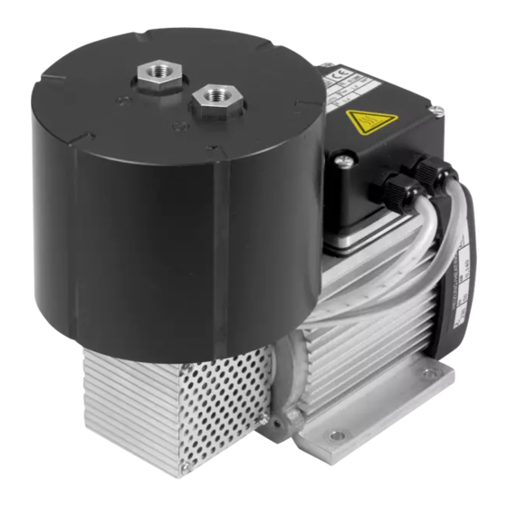
Diaphragm
Fig. 1: N 012 ST.26 E
List of Contents
1. Description, Operating Conditions............................................ 2
2. Safety ....................................................................................... 4
3. Installation ................................................................................ 5
4. Operation.................................................................................. 8
5. Servicing................................................................................. 13
6. Cleaning ................................................................................. 18
7. Trouble Shooting .................................................................... 18
8. Spare parts and accessories.................................................. 21
9. Tables..................................................................................... 22
10. Accessory ............................................................................... 22
11. Decontamination Declaration ................................................. 23
Page
Advertisement
Table of Contents

Related Manuals for KNF N 012 AT. 16 E


Summary of Contents for KNF N 012 AT. 16 E
-
Page 1: Table Of Contents
Type range: N 012 AT. 16 E N 024 AT. 16 E N 036 AT. 16 E N 036.0 AT. 16 E N 012 ST. 11 E N 024 ST. 11 E N 036 ST. 11 E N 036.0 ST. 11 E N 012 ST. -
Page 2: Description, Operating Conditions
Diaphragm Vacuum Pumps N 012, N 024, N 036 Description, Operating Conditions KNF pumps in the N 012, N 024, N 036 and N 036.0 range trans- fer, evacuate and compress 100% oil-free. In operation they are gas-tight (leak rate: 6 x 10 mbar x l/sec), and maintenance-free. - Page 3 The pump must not be used in areas where there is a danger of explosion. During operation an adequate supply of air for cooling must be provided. 1.4. Pump materials See section 9. Translation of original Operating and Installation Instructions, english, KNF 121222-121485 08/11...
-
Page 4: Safety
The pumps conform to the EC Directive 2004/108/EC concerning Electromagnetic Compatibility. The following harmonized standards have been used: DIN EN 61326-1 DIN EN 61000-3-2/3 DIN EN 60204-1 Translation of original Operating and Installation Instructions, english, KNF 121222-121485 08/11... -
Page 5: Installation
Electronic housing (.-26- design only) or terminal Draw the mains cables into the electronics housing or the cover (.-11-and .16- terminal cover through the free cable screw holes. designs) Translation of original Operating and Installation Instructions, english, KNF 121222-121485 08/11... - Page 6 Fig. 3a: Electrical connection (.11-designs: with themostatically regulated head heating) except for N 036_T.11 E) Fig. 3b: Electronical connection of N 036.0 _T. 11 E Translation of original Operating and Installation Instructions, english, KNF 121222-121485 08/11...
- Page 7 9. For flow direction see marking on the pump head or data sheet. Arrange the suction and pressure lines so that condensate cannot run into the pump (falling tubes). Translation of original Operating and Installation Instructions, english, KNF 121222-121485 08/11...
-
Page 8: Operation
If restriction or control of the air or gas flow is made on the pres- sure side ensure that the maximum permissible operating pressure is not exceeded. Translation of original Operating and Installation Instructions, english, KNF 121222-121485 08/11... - Page 9 Wear is usually indicated by a drastic reduction in the pneumatic performance. When replacing parts proceed as described in sec- tion 5. Ambient conditions: see section 1.3. Operating pumps with electronic temperature control (.26 designs) Translation of original Operating and Installation Instructions, english, KNF 121222-121485 08/11...
- Page 10 1. Insert CD into CD-ROM drive on the computer. 2. Install the PC software by running "Start_Setup.exe" or the Auto-setup routine. 3. Start the PC software by clicking on the "KNF-Pump Control" icon or running "KNF-Pump Control.exe". Fig. 5: Operating keys and 4.
- Page 11 4. N 036.0 in operating mode 4: Repeat the setpoint temperature process for head 2. To do this, press the SET-TEMP key twice. Translation of original Operating and Installation Instructions, english, KNF 121222-121485 08/11...
- Page 12 The pump head is heated up to the preset temperature, while the pump is not working. LED ON lights up in the Preheating key. 3. When the preset temperature is reached, the pump starts to transfer. Translation of original Operating and Installation Instructions, english, KNF 121222-121485 08/11...
-
Page 13: Servicing
Valve plates 2 (per pump head) Wave diaphragm 1 (per pump head) O-Rings 2 (per pump head) Tab. 1: Spare parts * According to Spare parts list, chapter 8 Translation of original Operating and Installation Instructions, english, KNF 121222-121485 08/11... - Page 14 Refitting pump head f.) Final steps. Proceed as follows (see fig. 6). For two-headed pumps: Perform and finish all work on one pump head before working on the second pump head. Translation of original Operating and Installation Instructions, english, KNF 121222-121485 08/11...
- Page 15 Retainer plate Diaphragm support Con-rod extension 10 O-ring 11 Valve plate Fig. 6: Pump head (symbolic) Fig. 7: Arrangement of the disk spring for material version of pump head Translation of original Operating and Installation Instructions, english, KNF 121222-121485 08/11...
- Page 16 6. Screw the retainer plate (7) with wave diaphragm (2) into the conrod extension (9); to tighten the retainer plate, use the wrench for retainer plate/the pin wrench to turn it clockwise and firmly. Translation of original Operating and Installation Instructions, english, KNF 121222-121485 08/11...
- Page 17 (N 036.0). 3. Reconnect the pump to the electricity supply. If you have any questions about servicing call our technical adviser (see last page for contact telephone number). Translation of original Operating and Installation Instructions, english, KNF 121222-121485 08/11...
-
Page 18: Cleaning
To measure the performance, disconnect the pump from the system (small diameter tubing or a valve can significantly affect performance). Translation of original Operating and Installation Instructions, english, KNF 121222-121485 08/11... - Page 19 If the pump does not operate properly and you cannot find any of the above faults, send it to the KNF Service Department. In order for KNF to repair the pump, the customer must provide a statement on the media which were pumped and on pump clean- ing.
- Page 20 Trouble Shooting Diaphragm Vacuum Pumps N 012, N 024, N 036 together with the pump. A sample statement for copying can be found in section 11 of these operating instructions. Translation of original Operating and Installation Instructions, english, KNF 121222-121485 08/11...
-
Page 21: Spare Parts And Accessories
Disk spring 056020 Tab. 4 N 036 _T.__ E N 036.0 _T.__ E Spare part Order No. Valve plate 054112 Wave diaphragm 054111 O-ring 055676 Disk spring 056021 Tab. 5 Translation of original Operating and Installation Instructions, english, KNF 121222-121485 08/11... -
Page 22: Tables
G 1/8´ N 024 xx .xx E G 1/8´ N 036(.0)12 xx .xx E G 1/4´ Tab. 8: Size of pneumatic port threads 10. Accessory Wrench for retainer plate 018812 Translation of original Operating and Installation Instructions, english, KNF 121222-121485 08/11... -
Page 23: 11. Decontamination Declaration
Diaphragm Vacuum Pumps N 012, N 024, N 036 Decontamination Declaration 11. Decontamination Declaration The condition for the repair of a pump by KNF is the certifica- tion of the customer on the transferred media and on the cleaning of the pump (decontamination declaration).
Need help?
Do you have a question about the N 012 AT. 16 E and is the answer not in the manual?
Questions and answers