Advertisement
Quick Links
Advertisement

Related Manuals for KNF UN 828


Summary of Contents for KNF UN 828
- Page 1 KNF 04/2022 UN 828 / UN 838 TRANSLATION OF ORIGINAL OPERATING AND INSTALLATION INSTRUCTIONS MINI DIAPHRAGM VACUUM PUMPS Note! Before operating the pump and the accessories, please read the operating instructions and pay attention to the safety precautions!
-
Page 2: Table Of Contents
KNF Inc 2 Black Forest Rd Trenton, NJ 08691 Contents Page ....About this document Phone +1(609) 890-8600 ................Safety ...... Technical Data http://www.knf.com/ ....Design and function ..Installation and connection ....... Operation ........ Servicing ..... Troubleshooting 10.Spare parts and accessories ........ - Page 3 An activity to be carried out (a step) is specified here. 1. The first step of an activity to be carried out is specified here. Additional, consecutively numbered steps follow. This symbol refers to important information. Original-Operating and Installation Instructions, English, KNF 121249-121517 09/19...
-
Page 4: Use
Before using a medium, check the compatibility of the materials of the pump head, diaphragm and valves with the medium. Only transfer gases which remain stable under the pressures and temperatures occurring in the pump. Translation of original Operating and Installation Instructions, English, KNF 121249-121517 09/19... - Page 5 The pumps are not suitable for transferring foodstuffs. The pumps are not suitable for use with aggressive media. Other pumps in the KNF product line are designed for use with aggres- sive media. Please contact us for more information. The pumps must not be used to create vacuum and overpressure simultaneously.
-
Page 6: Safety
This also applies for unusual operational situations. Note that the temperature of the medium increases when the pump compresses the medium. Translation of original Operating and Installation Instructions, English, KNF 121249-121517 09/19... - Page 7 In addition a protection against mechanical parts in motion and hot parts, if existing, has to be provided when mounting. Translation of original Operating and Installation Instructions, English, KNF 121249-121517 09/19...
- Page 8 Customer service and the pump regularly with regard to conspicuous changes in noise repairs and vibrations. Only have repairs to the pumps carried out by the KNF Customer Service responsible. Housing with voltage-caring parts may be opened by technical per- sonnel only.
- Page 9 Pressure and nomi- nal speed [l/min]* Flow rate at atm. Pressure and 0.1V control voltage (only .29-version) [l/min]* Tab. 6 *Liters in standard state (1013 mbar) Pneumatic connections Pump type Value Translation of original Operating and Installation Instructions, English, KNF 121249-121517 09/19...
- Page 10 See Label on Pump Pump power consumption Motor protection class: IP 00 UN 828 AN_ / UN 828 KN_ / UN 838 AN_ / UN 838 KN_ Motor protection class: IP 20 UN 838.1.2 KNI Maximum permissible mains voltage fluctuations ±...
- Page 11 Take all necessary care to prevent this leading to a dangerous situation. For UN 828 KNDC-B, UN 828 KN.29DC-B, UN 838 KNDC-B, UN 838 KN.29DC-B, UN 838.1.2 KNDC-B, UN 838.1.2 KN.29 DC-B: The pump is protected against overheating by a temperature sensor on the motor board and equipped with overcurrent pro- tection.
- Page 12 50% at 40°C / 104°F. Maximum altitude of installation 2000 / 6561 [m / ft above sea level]. **Contact KNF for operating above stated limit** Tab. 11 Translation of original Operating and Installation Instructions, English, KNF 121249-121517 09/19...
- Page 13 Inlet (suction side) Electrical connection Motor Fig. 1: Design UN 828 _NI Design UN 838 _NI Outlet (pressure side) Inlet (suction side) Electrical connection Motor Fig. 2: Design UN 838 _NI Translation of original Operating and Installation Instructions, English, KNF 121249-121517 09/19...
- Page 14 Outlet (pressure side) Inlet (suction side) Fig. 3: Design UN 838.1.2 KNI Design UN 828 _NDC Outlet (pressure side) Inlet (suction side) Motor Fig. 4: Design UN 828 _NDC Translation of original Operating and Installation Instructions, English, KNF 121249-121517 09/19...
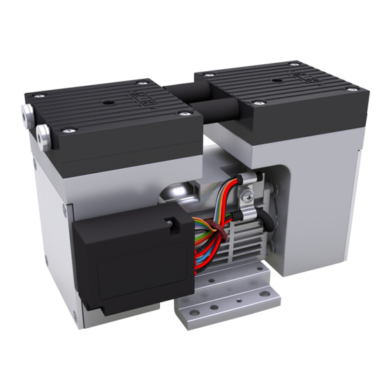
- Page 15 Fig. 5: Design UN 838 _NDC Design UN 828 KNDC-B and UN 828 KN.29DC-B Outlet (pressure side) Inlet (suction side) Motor controller Motor Fig. 6: Design UN 828 KNDC-B and UN 828 KN.29DC-B Translation of original Operating and Installation Instructions, English, KNF 121249-121517 09/19...
- Page 16 Design UN 838.1.2 KNDC-B and UN 838.1.2 KN.29DC-B Outlet (pressure side) Inlet (suction side) Motor Motor controller Pneumatic connection Fig. 8: Design UN 838.1.2 KNDC-B and UN 838.1.2 KN.29DC-B Translation of original Operating and Installation Instructions, English, KNF 121249-121517 09/19...
- Page 17 (1). The transfer chamber (3) is hermetically separated from the pump drive (7) by the diaphragm. Translation of original Operating and Installation Instructions, English, KNF 121249-121517 09/19...
- Page 18 UN 838 _NDC UN 828 KNDC-B and Fig. 15 UN 828 KN.29DC-B UN 838 KNDC-B and Fig. 16 UN 838 KN.29DC-B UN 838.1.2 KNDC-B and Fig. 17 UN 838.1.2 KN.29DC-B Translation of original Operating and Installation Instructions, English, KNF 121249-121517 09/19...
- Page 19 Diaphragm Vacuum Pump N 828 / N 838 Installation and connection 1/8 NPT 1/8 NPT Fig. 10: Mounting dimensions UN 828 _NI (All dimensional tolerances con- form to DIN ISO 2768-1, Tolerance Class V) *only N 828 KNE G 1/8 or 1/8 NPT G 1/8 or 1/8 NPT Fig.
- Page 20 DIN ISO 2768-1, Tolerance Class V) G 1/8 or 1/8 NPT G 1/8 or 1/8 NPT Fig. 13: Mounting dimensions UN 828 _NDC (All dimensional tolerances conform to DIN ISO 2768-1, Tolerance Class V) Translation of original Operating and Installation Instructions, English, KNF 121249-121517 09/19...
- Page 21 DIN ISO 2768-1, Tolerance Class V) G 1/8 or 1/8 NPT (2X) Fig. 15: Mounting dimensions UN 828 KNDC-B and UN 828 KN.29DC-B (All dimensional tolerances conform to DIN ISO 2768-1, Tolerance Class *Connection (X) only for UN 828 KN.29DC-B...
- Page 22 Fig. 17: Mounting dimensions UN 838.1.2 KNDC-B and UN 838.1.2 KN.29DC-B (All dimensional tolerances conform to DIN ISO 2768-1, Tolerance Class V) *Connection (X) only for UN 838.1.2 KN.29DC-B Translation of original Operating and Installation Instructions, English, KNF 121249-121517 09/19...
- Page 23 Make sure that vibrations of the pump do not re- sult in hazards associated with adjacent compo- nents. Protect the pump against contact and intrusion of foreign mat- Foreign matter protection ter. Translation of original Operating and Installation Instructions, English, KNF 121249-121517 09/19...
- Page 24 (strain relief). Pumps with AC motor are fitted as standard with a thermal switch to protect against overloading. Translation of original Operating and Installation Instructions, English, KNF 121249-121517 09/19...
- Page 25 (usual) A.C. / D.C. converter.” The test is applicable for D.C. power inputs which are foreseen for a permanent connection to cables which are longer than 10 m. Translation of original Operating and Installation Instructions, English, KNF 121249-121517 09/19...
- Page 26 Control voltage may only be applied if the motor controller is supplied with operating voltage. Otherwise damages can occur on the motor controller. Translation of original Operating and Installation Instructions, English, KNF 121249-121517 09/19...
- Page 27 Function Lead color Signal Name Size + Supply voltage AWG 18 - Ground (0V) black / GND AWG 18 Tab. 12 : Connection plan motor electronics UN 8__ K_DC-B Translation of original Operating and Installation Instructions, English, KNF 121249-121517 09/19...
- Page 28 & blue & orange UL 20932 5V Power supply U Control voltage range DC 5 ± 0.2 Max. current output [mA] Tab. 13 (part 1): Connection plan motor electronics UN 8__ K_.29DC-B Translation of original Operating and Installation Instructions, English, KNF 121249-121517 09/19...
- Page 29 Input level „low“ no error [0 … 0.9] Max. current carrying capacity [mA] Output impedance @ 1kHz [kΩ] ≥ 9 Tab. 13 (part 3): Connection plan motor electronics UN 8__ K_.29DC-B Translation of original Operating and Installation Instructions, English, KNF 121249-121517 09/19...
- Page 30 At the same time the default voltage for the white wire de- creases. Because of this the nominal final speed can no longer be reached. Fig. 20: Exposition Control without Potentiometer Fig. 21: Exposition Control with Potentiometer Translation of original Operating and Installation Instructions, English, KNF 121249-121517 09/19...
- Page 31 3. Connect the suction line and pressure line (see Chapter 4, Tab. 7 for mounting dimensions). 4. Lay the suction and pressure line at a downward angle to pre- vent condensate from running into the pump. Translation of original Operating and Installation Instructions, English, KNF 121249-121517 09/19...
-
Page 32: Operation
If the air or gas quantity in the pressure line is throttled or regulated, make sure that the maxi- mum permissible operating pressure is not ex- ceeded. Ensure that the pump outlet is not closed or con- stricted. Translation of original Operating and Installation Instructions, English, KNF 121249-121517 09/19... - Page 33 Switching off the pump / Restore the system to normal atmospheric pressure (release removing from operation pneumatic pressure in pump). Translation of original Operating and Installation Instructions, English, KNF 121249-121517 09/19...
- Page 34 Modify control voltage values U and U Ctrl min Ctrl max If the control voltage is less than U , the motor will be Ctrl min Translation of original Operating and Installation Instructions, English, KNF 121249-121517 09/19...
- Page 35 Tab. 13). To start the motor, the green wire must be bridged to the ground of the controller connection (grey wire, blue wire or or- ange wire). Translation of original Operating and Installation Instructions, English, KNF 121249-121517 09/19...
- Page 36 Reed-out of the following process parameters: Actual/Nominal motor speed Control limit of motor speed Operating current of the motor Temperature of the motor controller Fault status Software version number Translation of original Operating and Installation Instructions, English, KNF 121249-121517 09/19...
- Page 37 Nominal motor ns ; E speed Minimum possible nl ; E motor speed Maximum possible nh ; E motor speed Software version V ; E number Tab. 15: Reed commands Translation of original Operating and Installation Instructions, English, KNF 121249-121517 09/19...
- Page 38 See p. 28 for pin assignment of the motor controller’s commu- nication plug. Parameter Value Rx KNF MBLC Low: 0V…0.9V High: 4.2V…5.2V Tx KNF MBLC Low: 0V…0.6V High: 4.5V…5.2V Tab. 17 Translation of original Operating and Installation Instructions, English, KNF 121249-121517 09/19...
-
Page 39: Servicing
Solvent should be used for cleaning only if the head materials are not corroded (ensure compatibility of the material). If compressed air is available, blow out the parts. Translation of original Operating and Installation Instructions, English, KNF 121249-121517 09/19... - Page 40 Change the diaphragms and valve plates/sealings in the following sequence: a.) Preparatory steps b.) Remove pump head c.) Change diaphragm d.) Change valve plates/sealings e.) Refit pump head f.) Final steps. Translation of original Operating and Installation Instructions, English, KNF 121249-121517 09/19...
- Page 41 This helps avoid incorrect assembly later. 2. Undo the 4 screws (4) in the head plate and lift the head plate with the intermediate plate off the pump housing. Translation of original Operating and Installation Instructions, English, KNF 121249-121517 09/19...
- Page 42 5. Turn the fan to check that the pump rotates freely. 6. Turn the fan again to bring the structured diaphragm (7) to top dead center. 7. Now tighten screws (4) firmly diagonally (tightening-torque: 3.5 Nm). Translation of original Operating and Installation Instructions, English, KNF 121249-121517 09/19...
- Page 43 The pump head or motor may be hot even after the pump has been shut off. CAUTION Allow the pump to cool off after operation. Change the diaphragms and valve plates/sealings in the following sequence: Translation of original Operating and Installation Instructions, English, KNF 121249-121517 09/19...
- Page 44 Structured diaphragm Diaphragm spacer Screw 10 Screw cap 11 Disk spring Fig. 30: Pump head UN 828 KN_-versions (pump head made of plastic) 12 Washer a.) Preparatory steps M Marking 1. Remove the pumps from the source of electrical power. Make sure the pump is voltage-free and secure it.
- Page 45 7. Place the head plate (3) on the intermediate plate (2), in the position indicated by the marking (M). 8. Check that the head plate (3) is centered by moving it gently sideways. Translation of original Operating and Installation Instructions, English, KNF 121249-121517 09/19...
- Page 46 1. Only in the case of DC versions (no cooling fan): refix the cover (5). 2. Connect the pump to the electrical supply. If you have any questions about servicing call our technical adviser (contact data: see www.knf.com). Translation of original Operating and Installation Instructions, English, KNF 121249-121517 09/19...
- Page 47 Change the diaphragms and valve plates/sealings in the following sequence: a.) Preparatory steps b.) Remove pump head c.) Change diaphragm d.) Change valve plates/sealings e.) Refit pump head f.) Final steps. Translation of original Operating and Installation Instructions, English, KNF 121249-121517 09/19...
- Page 48 Undo the head-plate screws (4) in the head plate (3) and lift the two head-plates with the intermediate plates (2) and the pneumatic connections (13) off the pump housing. Translation of original Operating and Installation Instructions, English, KNF 121249-121517 09/19...
- Page 49 (9) with disk spring (11) and washer (12). Fig. 33: Orientation of the Torque for tightening the screw(s): 35 Ncm. disk spring (11) 10. Carry out steps 1. – 9. For the second pump head. Translation of original Operating and Installation Instructions, English, KNF 121249-121517 09/19...
- Page 50 838.1.2 KNI: refix the cover (1). 2. Connect the pump to the electrical supply. If you have any questions about servicing call our technical adviser (contact data: see www.knf.com). Translation of original Operating and Installation Instructions, English, KNF 121249-121517 09/19...
- Page 51 Flush the pump (see Chapter 8.2.1). Install the pump at the highest point in the system. Diaphragm or valve plates are Replace diaphragm and valve plates (see Chapter 8.3). worn. Tab. 22 Translation of original Operating and Installation Instructions, English, KNF 121249-121517 09/19...
- Page 52 Make sure that the shim rings have been replaced onto the have been replaced. diaphragm screw thread. Check head connection and hose connections for leaks. Tab. 23 Translation of original Operating and Installation Instructions, English, KNF 121249-121517 09/19...
- Page 53 2. Clean the pump (see Chapter 8.2.2). 3. Send the pump, together with completed Health and Safety Clearance and Decontamination Form, to KNF stating the na- ture of the transferred medium. Translation of original Operating and Installation Instructions, English, KNF 121249-121517 09/19...
- Page 54 External potentiometer for setting of the On request speed RS232 Level-Translator with SUB-D9 On request plug RS232Level-Translator with Micro-USB On request plug Completely connectorized control cable On request (analog or digital controlling) Tab. 25 Translation of original Operating and Installation Instructions, English, KNF 121249-121517 09/19...
-
Page 55: 11. Returns
“Service & Repairs” (Service & Repair at KNF) page. After the form is submit- ted KNF will contact you with an authorization number to ship against. Translation of original Operating and Installation Instructions, English, KNF 121249-121517 09/19... - Page 56 KNF worldwide Find your local KNF partner on www.knf.com...
Need help?
Do you have a question about the UN 828 and is the answer not in the manual?
Questions and answers