Table of Contents
Advertisement
Advertisement
Table of Contents

Subscribe to Our Youtube Channel
Summary of Contents for Fluke db PRUFTECHNIK SHAFTALIGN touch
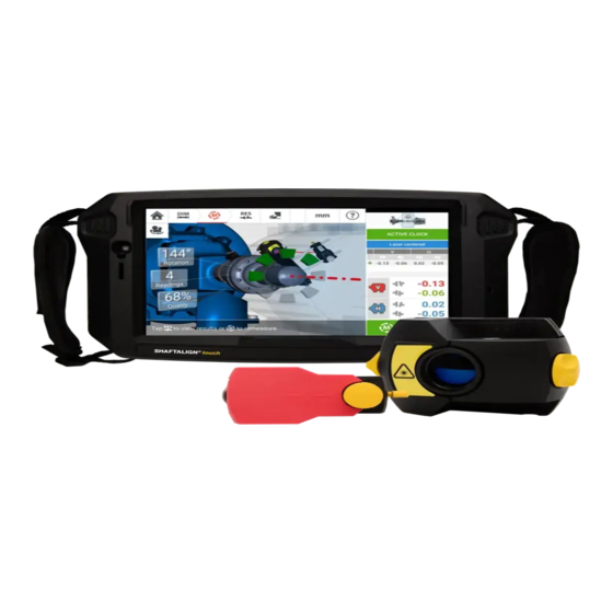
- Page 1 SHAFTALIGN touch ® On-board help...
- Page 2 SHAFTALIGN touch On-board help Version: 2.3 Edition: 07.2020 Part No.: DOC 26.200.EN...
- Page 3 Legal notices © 2020 Fluke Corporation. All rights reserved Information in this document is subject to change without notice. The software described in this document is distributed under a license agreement. The soft- ware may be copied only in accordance with the terms contained in this agree- ment.
-
Page 4: Table Of Contents
Contents Contents Introduction Using the on-board help Documentation Components Rugged device Device interface Charging the battery sensALIGN 3 sensor and reflector sensALIGN 3 sensor Sensor LEDs Charging the sensor Reflector Sensor and reflector labelling Home screen Configuration Built-in camera Gallery RFID Assigning a saved asset to an RFID tag Opening an asset measurement assigned to an RFID tag Using Cloud drive... - Page 5 Mount reflector Dimensions Machine properties Toggle Machine colour Thermal growth Thermal growth calculator Multiple feet Coupling properties Targets Tolerances Available tolerance tables ANSI standard specification tolerances User defined tolerances Asymmetric and symmetric tolerances Tolerance table based on coupling format Suggested consolidated shaft alignment tolerances Laser beam adjustment (sensALIGN 3) Adjusting sensor and reflector until the laser beam status LED blinks green Laser beam adjustment...
- Page 6 Static measurement Extend measurement range manually Measurement table Measurement quality Editing measurement data Broken ellipse What is the effect of deactivating individual points? Results Results options Sign convention Multiple feet results Foot corrections Live Move screen Saving asset measurements Saving an asset Asset list options Default template Generating reports...
- Page 7 Vertical flanged machines Marking measurement positions Set-up Vertical flanged machines – Static clock Measure using Static measurement mode Vertical results Shimming modes Sign convention Live Move – Vertical machines Correcting angularity Correcting offset sensALIGN 3 sensor firmware update Updating sensor firmware to a newer version Notification on sensor calibration Best practice Mounting sensor and reflector...
-
Page 8: Introduction
On-board help Introduction This on-board help provides information to support users of SHAFTALIGN touch. Using the on-board help The on-board help is accessed via the home screen. Tap the "Home" icon then the ques- tion mark icon to access the on-board help. Context sensitive help may be accessed from specific screens by tapping the question mark icon provided on the specific screen. -
Page 9: Documentation
On-board help The navigation pane hide arrow is used to hide the navigation menu items. Tap the arrow to hide or show the navigation menu items. This screen-specific help icon is used to access the context sensitive help. Note It is recommended to scroll to the bottom of the page to be able to access other related topics which are frequently used throughout the on-board help. ... -
Page 10: Components
On-board help Components The main measuring components for shaft alignment are the rugged device, the sensor and the reflector. Rugged device SHAFTALIGN touch... - Page 11 On-board help Power key – used to switch the rugged device on. Press and hold down the power key until the device turns on. Front camera Ambient light sensor Volume down button (refer to 'Note' below) (5)Strap (on either side of the device) (6)Rear camera (7)LED flash (8)Foldable stand –...
-
Page 12: Device Interface
On-board help Tap the "Power off" icon to switch the rugged device off. The Shaft application may be exited and device switched to sleep mode by tapping the power- off icon [ ] appearing in the home screen. A hint requiring confirmation to go to sleep mode appears on the display. to confirm selection. -
Page 13: Charging The Battery
On-board help The rugged device's multipurpose connector (11) is used for charging the device and con- necting it to a PC. When connected to a PC, data may be transferred from the tablet or a device firmware update may be performed. Charging the battery Charge the battery before using the rugged device for the first time or when the tablet has been unused for extended periods. -
Page 14: Sensalign 3 Sensor And Reflector
On-board help sensALIGN 3 sensor and reflector sensALIGN 3 sensor The sensor has an integrated Bluetooth, and contains a position detector, which measures the position of the laser beam as the shafts are rotated. The sensor also contains an electronic inclinometer for shaft rotation measurements. The semi- conductor laser diode within the sensor emits a ray of red light (wavelength 630 –... -
Page 15: Sensor Leds
On-board help Sensor LEDs Laser beam status and charging Laser on / Bluetooth com- Activity munication LED Switch on Lights up red for 1 second, then red Lights up blue for 1 second then con- or green (depending on the battery tinues to blink red (indicating laser capacity) for another second, then emission) -
Page 16: Reflector
On-board help The supplied micro USB is used to connect the charging source to the sensor. Reflector The reflector is always mounted on the shaft or solid coupling of the machine to be moved. It reflects the laser beam back into the position detector as the shafts are rotated. The locking lever flips into the horizontal position, facing forward, to hold the reflector in place on the bracket posts. -
Page 17: Sensor And Reflector Labelling
On-board help 1: Quick release lever; 2: Horizontal angle adjustment knob; 3: 90° roof prism; 4: Vertical position adjustment thumbwheel; 5: Measure mark = center of posts; 6: Support post (not part of reflector); 7: Reflector dust cap CAUTION Avoid vigorous polishing to preserve the anti-reflective coating. Keep the dust cap on the reflector when it is not in use. - Page 18 On-board help Type ALI 21.901 PRÜFTECHNIK GmbH 85737 Ismaning www.pruftechnik.com S.No. 2191 XXXX Made in Germany Date MM-JJJJ MM-JJJJ Contains IC: 5123A-BGTBT121 Contains FCC ID: QOQBT121 Contains Rechargeable Lithium Ion Battery 3.7 V 5 Wh R 209-J00171 MSIP-CRM-BGT- BT121 The label affixed on the back of the reflector The following text is found on the label: S.No.
-
Page 19: Home Screen
On-board help Home screen The home screen is displayed when the device is switched on. The home screen may also be accessed by tapping the "Home" icon. Tapping the respective icon accesses the following respective functions: The "Horizontal alignment" icon is used to access the horizontal alignment applic- ation. - Page 20 On-board help The "Asset park" icon is used to display all saved assets and templates. The "Resume" icon is used to resume last asset opened (provided it was saved) when the device is switched on. The "Gallery" icon is used to display all images taken within the Shaft application. (10) The "Upload"...
-
Page 21: Configuration
On-board help Configuration The following settings and items may be accessed via the configuration icon: 'System settings' sets the following items: > Language (system language); > Date; > Time; > Time zone; > Animation state — regulates the transition between the dimension, measure and res- ults screens. - Page 22 On-board help Note When using metric units, the resolution of physical quantities used within the device may be set to two (0.01 mm) or three (0.001 mm) decimal places. This measurement precision is available in "Measurement", "Results" and "Live Move" screens.
- Page 23 On-board help Note The rugged device may be connected only to WiFi networks that do not open sep- arate web browsers to login. Sensor list displays all available sensors. The "About" screen displays the device serial number, firmware version of the applic- ation and available memory space.
- Page 24 On-board help SHAFTALIGN touch...
-
Page 25: Built-In Camera
On-board help Built-in camera the 'Camera' icon to access the function. Focus the device on the object to be photographed. The object is displayed on the screen. Camera settings for indoor, outdoor and night imaging, including automatic light set- ting – Tap desired light setting icon (Flash may be turned on/off; Auto mode is for auto- matic light setting). - Page 26 On-board help Tapping opens the home screen. Tap any miniature to view the image in full scale. Images may be deleted from the gallery by tapping the desired image. This appears in full scale and may then be deleted by tapping the trash icon (1). The images in the gallery may be scrolled by using the arrow icons 2/3.
-
Page 27: Rfid
On-board help RFID The rugged device uses this automatic identification technology to perform the following: Identify assets to be aligned Enter corresponding assets directly into the device Store data and results under the correct asset automatically Assigning a saved asset to an RFID tag From the home screen, tap the "Asset park"... -
Page 28: Opening An Asset Measurement Assigned To An Rfid Tag
On-board help As soon as data has been written on the RFID tag, the corresponding hint appears on the dis- play. to exit the screen. Note If however, data had already been assigned to the RFID tag, a hint requesting over- writing of the data appears. Opening an asset measurement assigned to an RFID tag From the home screen, tap the "RFID"... - Page 29 On-board help to open the asset measurement. The asset name is displayed on the home screen. Tap the shaft alignment icon [1] to start the application. Note If however, no data had been written on the RFID tag, a hint on missing information appears.
-
Page 30: Using Cloud Drive
On-board help Using Cloud drive To set up the PRÜFTECHNIK Cloud drive, an ALIGNMENT RELIABILITY CENTER 4.0 (ARC 4.0) licence is required. The Cloud drive allows the sharing of up-to-date asset measurements from different devices via the PC software ARC 4.0. Note Wireless connection between the rugged device and a network must be established to enable assets to be transferred via ARC 4.0. -
Page 31: Mounting Components
On-board help Mounting components Mounting brackets Note The system is delivered with fully assembled brackets with both the sensALIGN 3 sensor and the reflector already assembled. In this case, the bracket holding the sensor is mounted on the shaft on the left side of the couplings or the solid coupling hub on the left side (usually stationary machine). -
Page 32: Mounting Sensor And Reflector
On-board help Mounting sensor and reflector Mount sensor Mount the sensor on the support posts of the bracket fixed on the shaft of the left machine (usually stationary machine) – as viewed from normal working position. Ensure that its yellow knobs are loosened enough to let you slide the housing onto the support posts. - Page 33 On-board help Lever The yellow knob on the front of the reflector allows you to adjust the horizontal angle of the reflected laser beam. Before you mount the reflector make sure that this knob is centered to allow for maximum adjustment range later on. The bottom of the knob should be flush with the arrow marking on the reflector housing.
- Page 34 On-board help Both sensor and reflector should be at the same height, as low as possible, yet just high enough for the beam to clear the coupling flange. They should also visually appear to be rota- tionally aligned to each other. In some cases, if the coupling is large enough, a coupling bolt can be removed and the laser beam shot through the bolt hole.
-
Page 35: Dimensions
On-board help Dimensions Grayed out icons are disabled within the active screen. The 'Measure' icon is enabled after all dimensions have been entered. Tap the measurement units icon to set desired units. The icon toggles between "mm" and "inch". Tap the dimension fields and enter all required dimensions. The user may elect to tap the ‘Next’... -
Page 36: Machine Properties
On-board help Machine properties The following lifelike machine graphics are available: 1. Generic standard machine; 2. Motor; 3. Pump; 4. Split case pump; 5. Fan; 6. Center hung fan; 7. Blower; 8. Compressor; 9. Gearbox; 10. Rotor gearbox; 11. Diesel engine; 12. Gen- erator;... -
Page 37: Thermal Growth
On-board help Swipe the colour palette up or down to select the desired colour then tap to confirm selection and return to the dimensions with the machines having the desired colour. Thermal growth Thermal growth is the movement of shaft centerlines associated with or due to a change in machinery temperature between the idle and operating conditions. -
Page 38: Thermal Growth Calculator
On-board help Thermal growth values are activated by swiping the icon to the right [1]. When thermal growth values are enabled, the corresponding machine within the mini train inset at the top- right corner appears in orange [2]. After thermal growth values have been entered, tap to proceed. -
Page 39: Multiple Feet
On-board help Tap (1) and select machine material. The corresponding linear thermal expansion appears. Enter the three values [2] required to calculate the thermal growth value for the selected feet pair using the onscreen keyboard [3]. The three values are: Ambient temperature (initial temperature) Machine running temperature (final temperature) Distance from machine base (or shimming plane) to the shaft centerline (length) - Page 40 On-board help If already entered, the 'Multiple feet' screen will show the dimension between the front feet and the back feet [1]. Note The intermediate machine feet are not displayed in the dimension screen. to add any intermediate feet. The intermediate feet pair is added after the front feet. Enter this dimension in the row that appears.
-
Page 41: Coupling Properties
On-board help Coupling properties Swipe the carousel up or down and select desired coupling type. The following coupling types are available for selection: Short flex — These couplings feature fitted transmission elements with play (such as teeth, claws or bolts) or elastic connecting elements like rubber ‘tires’ or springs. Spacer shaft —... - Page 42 On-board help After target values have been entered, tap to proceed. SHAFTALIGN touch...
-
Page 43: Tolerances
On-board help Tolerances Alignment quality is evaluated through comparison with tolerances based upon entered machine dimensions and RPM. The tolerance ranges are compiled as tables according to type of coupling, coupling format, and diameter (for the gap value) as well as RPM. When the coupling type is spacer, the tol- erance table values are determined by the length of the spacer shaft and the RPM. -
Page 44: Ansi Standard Specification Tolerances
On-board help Swipe the icon (1) to the right to enable tolerances. Tap (2) to select desired type of tol- erance. A pop-up menu (3) appears showing available tolerances. Tap desired type to display the corresponding tolerance table (4). ANSI standard specification tolerances The Acoustical Society of America (ASA) developed shaft alignment tolerances for both short flex and spacer couplings on standard rotating machinery. -
Page 45: User Defined Tolerances
On-board help User defined tolerances Swipe the icon (1) to the right to enable user defined tolerances. Asymmetric tolerances (2) can be activated only when user defined tolerances are enabled. In asymmetric tolerances, the tolerance values for the two coupling planes are not the same. Tap (3) to edit user defined tolerances using the onscreen keyboard (4). -
Page 46: Asymmetric And Symmetric Tolerances
On-board help Asymmetric and symmetric tolerances When asymmetric tolerances have not been enabled (1), the displayed specified tolerances (2) are symmetric. The gap and offset tolerances for both horizontal and vertical planes are identical. If asymmetric tolerances are enabled (3) all four specified values are displayed (4). SHAFTALIGN touch... -
Page 47: Tolerance Table Based On Coupling Format
On-board help Tolerance table based on coupling format For the same type of tolerance, RPM, and coupling diameter, the tolerances value differ according to the coupling format selected. Coupling format (1) is gap/offset for short flex coup- ling, and (2) is angle/offset for short flex coupling. Change coupling format by tapping 3. Note There are no tolerance tables for consolidated spacer shaft coupling formats. - Page 48 On-board help metric (mm) imperial (mils) Acceptable Excellent Acceptable Excellent Short flexible couplings 0.15 0.10 14.9 10.0 Gap (per 100 mm or 10" dia- 0.12 0.08 12.3 meter) 0.10 0.07 10.5 1000 0.10 0.06 1200 0.08 0.05 1500 0.07 0.04 1800 0.06 0.04 3000 0.04...
- Page 49 On-board help metric (mm) imperial (mils) Acceptable Excellent Acceptable Excellent Spacer shaft and mem- 0.30 0.18 brane (disk) couplings 0.24 0.14 Offset (per 100 mm spacer length or per 1" of spacer 0.20 0.12 length) 1000 0.18 0.11 1200 0.15 0.09 1500 0.12 0.07...
-
Page 50: Laser Beam Adjustment (Sensalign 3)
On-board help Laser beam adjustment (sensALIGN 3) Adjusting sensor and reflector until the laser beam status LED blinks green Note Make sure that the reflector and sensor lens are clean. Use a soft lint-free cloth. A lens cleaning cloth is supplied. The sensor and reflector need to be adjusted so that the laser beam strikes the reflector and is reflected back into the sensor. - Page 51 On-board help The lever (3) must always be in the horizontal position except for mounting and dis- mounting. horizontally: loosen one of the brackets on the shaft and rotate it slightly and then retighten. This correction is necessary if the laser beam is too far left or right. 4.
-
Page 52: Laser Beam Adjustment
On-board help Laser beam adjustment Laser adjustment wizard The laser adjustment wizard is the primary laser beam adjustment feature in the touch device. If the sensor is initialized, and the laser beam is not centered, use the wizard to adjust the laser beam correctly. - Page 53 On-board help improves, disappearing completely once the laser beam is centered. Measurement may commence once the laser beam is centered. Version:2.3...
-
Page 54: Xy View
On-board help XY View The XY View function is used to facilitate the centering of the laser beam on the position detector before proceeding with measurement. Tap the shown detector area to directly access the XY View screen. The XY View screen may be accessed using the menu item "XY View" which appears when the "sensor area"... - Page 55 On-board help If the laser beam status is "OK" or "Centered" [1] tap "Set to zero" [2] to set the current laser dot position as 0,0. The rX,rY values are then monitored to check the stability of the values. Tap "Absolute" to return to the absolute values. Note that the menu items on the screen may be used to display following items: Sensor list –...
-
Page 56: Initializing Sensor
On-board help Initializing sensor The hint "Communication error" [1] suggests that the sensor has not been initialized although the laser beam may have been correctly adjusted. Tap the detector and sensor area [2] to access the menu item 'Sensor list'. Tap menu item 'Sensor list' [1] to view scanned sensors. -
Page 57: Measurement
On-board help Measurement Active Clock is the default measurement mode for horizontal machines, and Static Clock is the default mode for vertical machines. For horizontal machines, Static Clock measurement mode may be selected while in the meas- urement screen. Tap the measurement mode header [1] to access the measurement mode carousel. Swipe the carousel up or down and select desired measurement mode. - Page 58 On-board help aging also improves the accuracy when measuring sleeve bearings, white metal bearings and journal bearings. Set the averaging by tapping the 'Averaging' button [1]. A scale [2] used to set the averaging value appears on the screen. Tap desired averaging value which then appears in the 'Aver- aging' button [1].
-
Page 59: Measurement Modes
On-board help Measurement modes The following measurement modes are available in SHAFTALIGN touch: Active Clock – This is the default measurement mode used to measure horizontal stand- ard coupled machines. In this mode, measurement points are taken at any 3, 4 or 5 of the eight available sectors. -
Page 60: Active Clock Measurement
On-board help Active Clock measurement In Active Clock, measurement points are taken at the 8 available sectors. The range in which the sectors become active and therefore points may be taken is the given clock position (in degrees) + 11.25 degrees. For example, the 1:30 o'clock position will be active when the sensor and reflector are at a rotational angle between 34 - 56 degrees. - Page 61 On-board help After measurement is taken, the sector is highlighted red. This is an indication of the meas- urement quality. Rotate shafts to the next sector and repeat the previous step for the set act- ive points. The color of the measured sectors shows the attained measurement quality. The proceed icon (1) also indicates the attained measurement quality.
-
Page 62: Taking Measurement Points Automatically
On-board help Rotational angle covered by the shafts Active clock measurement points taken (in this example set points attained) Measurement quality attained Hint (in this example set points attained) Coupling results displayed as soon as the measurement quality reaches 40% (active clock sector is orange) to re-measure machines. - Page 63 On-board help Version:2.3...
-
Page 64: Static Measurement
On-board help Static measurement This measurement mode is used for uncoupled shafts, nonrotatable shafts and vertical foot- mounted or flange-mounted machines. If not yet completed, enter dimensions then center laser beam. Use the measurement mode carousel and select static measurement mode (Static Clock). 'The 'left/right' navigation icons are used to position the displayed sensor and reflector at an angular position corresponding to the actual position of the components as mounted on the shafts. - Page 65 On-board help Note After taking a measurement point, the displayed sensor and reflector move to the next clock position on the display. If shaft rotation restrictions hinder the taking of measurements at particular shaft pos- itions, bypass these using . Measurements must be taken in at least three positions over 90°, but more measurements over a wider angle is recommended.
-
Page 66: Extend Measurement Range Manually
On-board help Extend measurement range manually Measurement range may be extended manually in both Active Clock and Static measurement modes. This range extension allows the adjustment of the laser beam such that it does not miss the detector surface when measuring shafts with gross misalignment or angular mis- alignment over large distances. - Page 67 On-board help With the laser beam centered, tap then continue with measurement by rotating the shafts further. After rotating the shafts through as wide an angle as possible, tap (1) to proceed to results, then (2) to view results. Note If taking measurements using the Active Clock mode, it is recommended to take all set active measurement points.
-
Page 68: Measurement Table
On-board help Measurement table The measurement table is used to register and display all Shaft alignment, and any Live Move measurements taken on the current couplings. Access the measurement table by tapping either the results repeatability table or coupling results / (3). - Page 69 On-board help Tap the check box to include the measurement in calculating the averaged results that is displayed on the results screen. Included measurements have a green check mark. The check mark remains grayed out if the measurement is not selected. Measurements in chronological order Used measurement mode The rotational angle covered during measurement...
-
Page 70: Measurement Quality
On-board help (12) Direction of shaft rotation during measurement (13) Serial number of sensor used and recalibration due date The "AS FOUND" coupling result (14) shows the initial alignment condition of the machines before any Live Move is performed. The displayed result could be an average of selected meas- urements. - Page 71 On-board help Rotation evenness – the smoothness of the measurement rotation e.g. if there is any fric- tion during the rotation that ‘jerks’ the shaft Angle rotation inertia – abrupt changes in the measurement rotation speed e.g. releas- ing and re-applying a break during the rotation Rotation direction –...
-
Page 72: Editing Measurement Data
On-board help Editing measurement data To improve the quality of the alignment results, it is possible to edit measurement data that could have been affected by external circumstances such as bracketing touching piping arrangement. The editing options are accessed via the measurement table. When in the measurement table screen, tap desired measurement (1) then tap (2) to access the measurement data screen. -
Page 73: What Is The Effect Of Deactivating Individual Points
On-board help to cycle through the points. Currently selected point is active. The point is made inactive by tapping 'Deactiv- ate'. Shows coupling results for selected measurement. In this example, all meas- urement points are active. to automatically select the point with the highest deviation within the dia- gram. -
Page 74: Results
On-board help Results Displays both horizontal and vertical foot results simultaneously Used to display vertical foot results only Used to display horizontal foot results only Used to display foot results in 2-D Used to display foot results in 3-D Starts Live Move Used to generate asset measurement report Used to save asset measurements in asset park Used to select results mode... -
Page 75: Results Options
On-board help Vertical foot position results Horizontal foot position results Vertical coupling results Horizontal coupling results Selected results mode Alignment condition tolerance symbol Horizontal and Vertical foot results in 2-D Results options Alignment results may be displayed in three different options. To access the available options, tap 1. -
Page 76: Sign Convention
On-board help Use the results mode carousel to select the desired results option then tap to confirm selection. The following options are available: ‘Actual’ – used to show just the measured alignment values without regard to any target values or thermal growth values that have been entered, even if they are active ‘Specification’... -
Page 77: Multiple Feet Results
On-board help Multiple feet results Foot corrections Foot corrections in a multiple feet machine are viewed from the result screen. If results are displayed in 3D, tap the machine (1) to access the results multiple feet screen. In 2D, the multiple feet screen is accessed by tapping the machine centerline (1). Note If the machine intermediate feet were already defined within machine properties, then the foot corrections for the intermediate feet will be displayed. - Page 78 On-board help Enter the dimension between the front feet and the intermediate feet in the row that appears then tap The foot correction values for the intermediate feet appear in the corresponding row. SHAFTALIGN touch...
-
Page 79: Live Move Screen
On-board help Live Move screen Note Aligning of machines involves vertical movement through shimming of the machine feet, and horizontal movement by shifting machine sideways. If the alignment condition of the machines is within tolerance (indicated by then there is no need to align the machines. It is recommended to perform vertical corrections first, since the horizontal condition is easily affected by the process of loosening anchor bolts and inserting and/or removing shims, whereas the vertical condition is less prone to being affected when performing... - Page 80 On-board help In Static measurement mode, four 45° positions (10:30, 1:30, 4:30 and 7:30 o'clock position as viewed towards the sensor) are available. In Active Clock, the Live Move screen appears if the laser has been centered and the shafts are rotated to any one of the four sectors.
- Page 81 On-board help to confirm changing Live Move planes. The sensor- reflector position selec- tion screen appears. Proceed to position the displayed sensor as described previously. After loosening the anchor bolts, correct the alignment condition by moving the machine feet in the direction of the color coded bold arrows, keeping an eye on the smiley on the display screen.
- Page 82 On-board help If the laser beam is not centered, use the laser beam adjustment wizard, or use the XY view screen to center the laser dot. Tap the detector area on the screen [1] to access the XY View. Note If the vertical view (V) is selected when the function Live Move function is started, only the vertical condition will be displayed.
-
Page 83: Saving Asset Measurements
On-board help Saving asset measurements Saving an asset Before switching off the instrument, dimensions, measurements, results and all settings can be saved for analysis, future use or record purposes in the instrument’s memory or trans- ferred via Cloud or USB to ARC 4.0 the PC software. Asset measurements are saved from the results screen. -
Page 84: Asset List Options
On-board help The status envelopes indicate whether an asset has been measured or not. This icon shows that the asset has been imported from ARC 4.0 but is yet to be opened. This icon shows that the asset has been opened but the alignment measurement has not been completed. - Page 85 On-board help Assigns selected asset to an RFID tag. Opens the selected asset a new asset. The new asset will be a copy of the selected asset without the sensor-to-refletor dimension, and any asset measurements. Start desired application by tapping the appropriate icon on the home screen. The new asset opens and may be edited as required.
- Page 86 On-board help > Tap to save the asset as a template. > Enter name of template then tap Note If for any given reason, the template is not to be saved, tap the cancel icon [ to cancel saving. SHAFTALIGN touch...
- Page 87 On-board help > The created template now appears on the template list. Used to delete selected asset. Used to exit the asset list/template list screen and return to the home screen. This symbol ( ) signifies that the selected asset is open and running in the background.
-
Page 88: Default Template
On-board help Default template It may be necessary to define any one template as the default template. The default template will be used whenever a new asset is opened within the home screen. > All available templates are listed on the template list. >... - Page 89 On-board help Note: If no template is selected, all template list options are unavailable. Version:2.3...
-
Page 90: Generating Reports
On-board help Generating reports Generating measurement reports Asset measurement reports may be saved directly on the rugged device as PDF. Measurement reports are generated from the results screen. Tap the menu item "Report". The "Generating report" screen opens. In this example, none of the "Generating report" menu items has been activated. To activate any of the items, tap the respective icon When "Machine alignment information"... -
Page 91: Report Logo
On-board help Location where asset is positioned Asset (Machine) ID Name of operator Any other machine relevant notes Date is set automatically In this case, "Results as found" has been activated The following elements are also found on the "Generating report" screen. to preview the asset measurement report to save the asset measurement report as PDF to the rugged device. - Page 92 On-board help "SHAFTALIGN touch\Tablet\Media\Logos". Disconnect the rugged device from the PC and then tap the "Add report logo" icon The report logo gallery opens. From the report logo gallery, tap the desired logo and then tap . The selected logo will now appear on the PDF measurement report when "Show report logo" is activated. Note: The delete icon is active.
-
Page 93: Saving Report To Usb Drive
On-board help Saving report to USB drive Asset measurement reports may be saved as PDF to a USB drive. Measurement reports are generated from the results screen. Connect the rugged device to a USB drive using the provided USB C to USB A adapter then tap the menu item "Report". - Page 94 On-board help The first time a USB drive is connected to the rugged device to save a report, the following screen appears. This screen is used to determine the location to save the report. Tap the hamburger menu icon next to "Recent". Drop down menu items appear. Tap the menu item corresponding to the connected USB drive (in this example "USB4REPORTS").
-
Page 95: What Is Soft Foot
On-board help What is soft foot Soft foot is the condition of machine frame distortion. Any cause that results in machine frame distortion when the machine is anchored to its foundation is a soft foot. Some of the principal causes are: Non-coplanar machine mounting surfaces Deformed machine frame or feet External forces e.g. -
Page 96: Checking And Correcting Soft Foot Conditions
On-board help With angular soft foot, the base of the foot is at an angle to its foundation and they are only partly in contact. In this case, suspect foot is checked with a feeler gauge and corrected by building a custom ‘shim wedge’ or machining the underside of the foot. Checking and correcting soft foot conditions The three main types are parallel soft foot, angular soft foot, and induced soft foot. -
Page 97: Soft Foot
On-board help Soft foot Soft foot measurement can be started from any screen where the 'Soft foot' icon [ ] is act- ive. Tap to start soft foot measurement. The values may be determined by sensor meas- urement or entered manually from values established using manual methods such as feeler gauges and shims. - Page 98 On-board help Once the sensor and reflector have been positioned horizontally, the on-screen needle rests on the respective green sector, and the following adjustment screen appears. Loosen the corresponding foot bolt (see hint 1). The recorded soft foot value is displayed [2]. When the soft foot value stabilizes, tap the 'Proceed' icon or recorded value (2), then tighten the bolt (see hint 1).
-
Page 99: Manual Entry
On-board help To proceed with soft foot measurement, tap . The following screen appears. Rotate the shafts to position the sensor and reflector at the correct angular position. Use the on-screen needle (2) as guidance. The needle should rest on the green sector. Manual entry Manual values may be determined using feeler gauges. - Page 100 On-board help Vertical flanged machines A typical vertical machine arrangement comprises one machine mounted on top of the other using a bolted flange. Flange-mounted machines may have a vertical or horizontal orientation. In either case, align- ment corrections are made directly at the flange. Angularity is corrected by inserting or removing shims between the flanges.
- Page 101 On-board help Mark a reference position on the machine close to the shaft and in line with a convenient external reference or flange bolt. Likewise, mark a reference point on the shaft. Measure the circumference of the shaft and divide by eight. Use this distance to make seven more evenly-spaced marks on the shaft beginning at your chosen start point.
- Page 102 On-board help Set-up Mount the sensor and the reflector on either side of the coupling, ensuring that they are aligned with the 0 or reference mark. Switch the touch device on, then tap in the home screen to start the vertical align- ment application.
- Page 103 On-board help Tap 'Flange' to access the "Flange details" screen where the flange may be edited. Tap the 'Shape' area [1] to select the shape of the flange from the pop-up menu [2] that appears. In the above example, the selected shape of the flange is "Circle". Tap the 'Layout' area [3] to select the pattern formed by the bolts from the pop-up menu that appears.
- Page 104 On-board help Vertical flanged machines – Static clock Measure using Static measurement mode Center the laser beam. Note Static measurement mode is used for vertically mounted machines. Rotate the shafts to the first measurement position. If using the coupling housing num- bering convention, the reference mark and the measurement position 0 should be aligned or matched to each other.
- Page 105 On-board help to proceed to view measurement results. Note The colour of the "Proceed" icon [ ] denotes the attained measurement quality. Note If flange dimensions have not been defined, the flange icon appears. Tap to enter missing flange dimensions. to view measurement results.
- Page 106 On-board help Vertical results Flange correction in 0-6 direction Flange correction in 3-9 direction Bolt position Shimming values Coupling gap and offset in the 0-6 direction Coupling gap and offset in the 3-9 direction Shim correction modes Shim correction mode used in this example Initiates Live Move (10) Tapping the coupling results area accesses the measurement table.
- Page 107 On-board help Viewpoint is always determined by looking from the reflector towards the sensor. Note: The little clock face on the sensor serves as a reminder of the viewpoint. WARNING When the sensor is switched on, the laser beam is emitted. DO NOT stare into the laser beam! ...
- Page 108 On-board help Live Move – Vertical machines Alignment is carried out by correcting angularity and offset. Angularity corrections are made by shimming at the given bolt locations. Offset corrections are made by moving the machine laterally. Correcting angularity It is recommended (but not obligatory) to correct angularity first: 1.
- Page 109 On-board help 2. Tap to start Live Move. A hint screen prompting the positioning of the sensor and reflector in any one of the four designated 45° positions (10:30, 1:30, 4:30 and 7:30 o'clock position – as viewed towards the sensor) appears. 3.
- Page 110 On-board help The selected Live Move direction (in this example 3 to 9) Arrows indicate direction and magnitude to move machine Tolerance coded gap and offset coupling values Tapping the 'Undo' icon allows user to re-measure or start Live Move afresh Tapping the 'Proceed' icon allows user to re-measure or start Live Move afresh 5.
- Page 111 On-board help 7. When offset is in tolerance as indicated by a happy smiley [ ] (excellent tolerance) or an OK icon [ ] (acceptable tolerance), tighten the flange bolts then tap to remeasure and check to confirm if the new alignment condition is in tolerance. 8.
- Page 112 On-board help sensALIGN 3 sensor firmware update Updating sensor firmware to a newer version It is possible to carry out a sensor firmware update directly via the rugged touch device. If a sensor with an older firmware version is connected via Bluetooth to the rugged device, a sensor firmware update notification appears on the display.
- Page 113 On-board help Once the update process is successfully completed, the following screen appears. The sensor has now been updated to the newer version available on the rugged touch device. to exit the update screen. The new sensor firmware version appears under "Sensor properties" which is accessed by tap- ping either sensor area in the measurement screen.
- Page 114 On-board help If the sensor firmware update is not carried out when the notification appears, the update action may be initiated via "Sensor properties". An "UPDATE" hint appears next to the older sensor firmware version. Tap "UPDATE" to proceed with the sensor firmware update. Note The sensor firmware update notification continues to appear once everyday until the firmware update is completed. ...
- Page 115 On-board help on the round label affixed to the back of the sensor. The sensor should be returned to an authorized PRÜFTECHNIK service center for cal- ibration checking. You may contact your local PRÜFTECHNIK representative for assist- ance or visit www.pruftechnik.com. Note The calibration due date is also found under "Sensor properties".
- Page 116 On-board help If the sensor calibration due date has expired and the sensor is connected via Bluetooth to the rugged touch device, a calibration expiry notification appears on the display. to close the notification. SHAFTALIGN touch...
- Page 117 On-board help Best practice Mounting sensor and reflector The 'Dimensions' screen shows the sides where the sensor and reflector are to be moun- ted. If necessary, use , the “Camera” icon to rotate the view on the screen to allow machines be viewed as they physically appear.
- Page 118 On-board help tapping (1). Causes that may influence measurement Incorrect or loose mounting of bracket frame, support posts Incorrect or loose mounting of sensor and reflector on the support posts Loose machine anchor bolts Unstable or damaged machine foundation Mounted components strike machine foundation or machine casings or frame during shaft rotation High breakaway torque from rotatable and non-rotatable shafts Coupling backlash...
- Page 119 On-board help Appendix Updating SHAFTALIGN touch to a newer firmware version Check the PRÜFTECHNIK website (www.pruftechnik.com) to obtain the latest version. If in doubt, please contact your local representative or PRÜFTECHNIK Condition Monitoring. Download the update file to the desired directory on a PC. Switch the rugged device on then connect it to the PC.
- Page 120 On-board help Transfer the "update.rom" file to the rugged device folder "FirmwareUpdate". After the update file has been copied to the "FirmwareUpadte" folder, disconnect the rugged device from the PC. The following hint appears. Note DO NOT tap the device or press any of the hard keys. Wait for the next hint to appear. ...
- Page 121 On-board help Note Follow all the update instructions carefully, and confirm all requested installations. Once the update is completed, a hint to restart the tablet device appears. Press and hold down the power key briefly. "Power off" and "Restart" icons appear on the display.
- Page 122 On-board help Technical data – Rugged touch device SHAFTALIGN touch rugged device Processor: Exynos 7 Octa, 1.6GHz Octa-Core (Cortex®-A53) Memory: 3 GB RAM, 16 GB Flash memory Display Technology: TFT Resolution: 1280 x 800 Pixel Size: 203.1 mm (8") Connectivity Wi-Fi: 802.11 a/b/g/n/ac (2.4 GHz +5 GHz) Bluetooth Version: 4.2 RFID...
- Page 123 On-board help Technical data – sensALIGN 3 sensor sensALIGN 3 sensor Measurement prin- Coaxial, reflected laser beam ciple LED indicators 1 LED for laser beam status and battery status ® 1 LED for Bluetooth communication Power supply Battery: Lithium-Ion rechargeable battery 3.7 V / 5 Wh Operating time: 10 hours (continuous use) Charging time: Using charger –...
- Page 124 On-board help CE conformity Refer to the CE compliance certificate in www.- pruftechnik.com Country radio cer- Approvals granted for specific regions (refer to the provided tifications 'Safety and general information' document) Technical data – Reflector (prism) Reflector (prism) Type 90° roof prism Accuracy (avg): >...
- Page 125 On-board help Index Extend 65 Extend;measurement range 65 Active Clock 56, 58-59, 78 Adapter;USB C to USB A 92 Firmware update 119 ANSI 43 ARC 4.0 82 asset measurement report 114 Asset park 82 Gallery 24 Asset;saving 82 Asymmetric tolerances 45 Averaging 56 Home screen 18 Backlash 59...
- Page 126 On-board help Soft foot; angular 94 Soft foot;correcting 95 On-board help 7 Soft foot;manual entry 98 Soft foot;parallel 94 Spacer shaft 40 PDF;USB drive 92 Standard deviation 56, 68 PRÜFTECHNIK service center 114 Static Clock 56, 63 Static measurement 58 Static measurement mode 79 Status envelopes 83 Quality factor 68...
- Page 127 On-board help Wireless connection 21 XY view 81 XY View 53 SHAFTALIGN touch...
Need help?
Do you have a question about the db PRUFTECHNIK SHAFTALIGN touch and is the answer not in the manual?
Questions and answers