Table of Contents
Advertisement
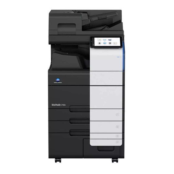
INSTALLATION MANUAL
[Important]
Be sure to correctly follow the procedures in order as explained in this Installation Manual.
If you do not follow the procedure in order, the image trouble may occur.
1. Outline of installation procedures
OT-514
When installing the main body and associated options as a system, follow the order shown on the upper.
Main body mass: approx. 160 kg (352-3/4 lb)
• Lifting the main body in an awkward position or transporting it in a poorly bal-
Note:
• For the detailed installation procedures for each option, follow the instructions given in the correspond-
ing installation manual and perform the procedures correctly.
• Once the Power Switch is turned ON, do not turn OFF it until the installation work has been completed.
2020. 9 Printed in Malaysia
HT-509
TK-101
SP-501
Main body
MK-730
EM-908
UK-221
SC-509
CU-102
IC-420
FK-514
FK-515*
FS-539(SD)
RU-519
PK-524
anced position could result in personal injury. When transporting the main
body, assign an adequate number of persons to the job and ensure that each
person can take a good position of not being excessively loaded.
MK-734
LU-205
LU-303
WT-519
AU-102
AU-201S
EK-609
VI-516
MK-742*
FS-540(SD)
ZU-609
PI-507
JS-602
PK-526
CAUTION
E-1
Applied Machines:
WT-506
EK-608
MK-735
KP-102
KH-102
*: Varies depending on the
applicable marketing area.
ACKN-9601-01
Advertisement
Table of Contents

Related Manuals for Konica Minolta bizhub C750i


Summary of Contents for Konica Minolta bizhub C750i
- Page 1 INSTALLATION MANUAL Applied Machines: [Important] Be sure to correctly follow the procedures in order as explained in this Installation Manual. If you do not follow the procedure in order, the image trouble may occur. 1. Outline of installation procedures HT-509 MK-734 TK-101 SP-501...
- Page 2 (Unit: mm (inch)) (1) Select a level and stable place for installing the machine. bizhub C750i + FS-540SD + LU-205 (2) Be sure to use a power source of the voltage and frequency indicated in the product specifi- 2492.5 (98-1/8) cations.
-
Page 3: Accessory Parts
5. Accessory parts Name Shape Q’ty 12. Waste toner Name Shape Q’ty 1. Installation 1 set manual 13. Leg assy 2. Quick guide 14. Chart 3. User’s guide CD *1 4. DVD *1 15. Cable clamp (large) 5. Paper size la- bel *2 16. - Page 4 WARNING If a power cord is not supplied, use only the power cord that meets the following conditions. Failure to do this could result in a fire or electrical shock. • The power cord has voltage and current rating appropriate for the rating plate on this machine.
- Page 5 6. Precautions on transporting the main body Do not lift the machine by holding the handle. Be sure to secure the four handles with the supplied screws B after installation. CAUTION Be sure to secure handles. If you accidentally hold the handle and lift the ma- chine, resulting in an injury.
- Page 6 (2) Hold onto the handle of the main body and tilt 7. Unpacking the main body the main body to the right and left. Under this Whether the slope is supplied with the main body or condition, remove the fixing materials. not depends on your marketing areas.
- Page 7 (4) Remove each one set of cushions from the (7) Holding the four handles at the right and left of trays 3 and 4 of the main body. the main body, slide the main body down along the slope. CAUTION Main body mass: approx.
- Page 8 (3) Pull out the tray 1 and remove the accessory ■ How to use the jig slope parts. (1) Open the shipping box and remove the pack- aging materials. Nail Note: Do not use the corrugated cardboard as the slope. (4) Position the slope as illustrated and insert the nails into the holes to fix the slope in position.
-
Page 9: Removing Protective Tape, Packing And Other Shipping Materials
(5) Holding the four handles at the right and left of (2) Remove the protective tape and the protective the main body, slide the main body down along materials. the slope. Note: Be sure to lock the lever after removing the pro- CAUTION tective tape A. - Page 10 (3) Open the right door and remove the protective (7) Slide out the tray 2 and remove the tray locking sheet and the locking materials. materials. Note: • After removing the locking materials, make sure that the transfer roller assembly is se- cured in place.
- Page 11 (11) Slide out the tray 4 and remove the protective (15) Attach the supplied scanner cover. (One sup- tape and protective material. plied screw A and one cap) (12) Remove the desiccant and the locking screw from the tray 4. (16) Remove the protective sheet.
- Page 12 (18) Open the lower front door. (21) Release the lever of the drum unit. (19) Remove the protective tape on the lower front (22) Slightly slide the drum unit out and remove the door. protective tape and protective material. (20) Remove the four locking materials. (23) Slide the drum unit into the main body.
-
Page 13: Installing The Toner Cartridge
(4) Push the toner cartridge all the way in. 9. Installing the toner cartridge Note: Note: Make sure that the toner cartridge is pushed all Since cartridge is not supplied with the machine, the way in. purchase toner cartridge separately. (1) Shake the toner cartridge up and down and left to right 5 to 10 times respectively. -
Page 14: Connecting The Power Cord
(2) Insert the stylus pen into the holder at the right 12. Connecting the power cord side of the main body. Note: Note: Steps (1) and (2) may be unnecessary depending The attachment hole at rear of the control panel on the applicable marketing area. - Page 15 13. Starting the machine 17. Performing Non-Image Area Erase Check Open the power switch cover on the right side of the main body, and turn ON the main power switch. Note: Perform the below at the site where customer uses the machine. 14.
- Page 16 (3) Move the front cover assy while taking notice 18. Aligning the front covers (Trays 3 and of the scale on the cover and the reference line on the screw. Note: Perform this procedure if necessary. (1) Check if there is any position misalignment among the front cover of the tray 2 of the main body and the front covers of the trays 3 and 4.
- Page 17 (7) Move the front cover assy while taking notice 19. Changing paper size (Tray 3, tray 4) of the scale on the cover and the reference line Note: on the screw. Perform this procedure only when changing the default paper size (Inch area: Letter, Metric area: A4) is required.
- Page 18 <Only for changing the paper size to B5 , 16K , (4) Remove the paper guide plate (front/rear). > • Paper guide plate (front): Four SEMS II screws (3) Remove the end guide plate (front). (Two • Paper guide plate (rear): Four bind screws screws) <Inch area>...
-
Page 19: Configuring Other Options
(6) Place a sheet of paper as large as the paper <Only for changing the paper size to B5 , 16K , size you are setting in the bottom of the tray. > Align the paper guide plate (front) with the end (9) Align the end guide plate (front) with the line of the sheet. -
Page 20: Adjusting Each Option
b) Route the network cable through the harness 22. Adjusting each option guide and five wire saddles. If any of the following options are installed, adjust Note: each option as necessary. (Refer to the “Adjustment Leave an appropriate amount of slack in the por- procedures”... -
Page 21: Network Setting
24. Network setting 26. Affixing the labels Make the TCP/IP address setting for the network. (1) Affix the paper size labels that correspond to the sizes of paper used in each tray. Note: Consult the network administrator for the setting value to be entered and make settings as re- quired. -
Page 22: Installing The User's Guide Holder
27. Installing the user’s guide holder 28. Securing the main body Install the user’s guide holder. (1) Move the main body to the installation site. Then, lock the two casters at the front to let the Note: main body sit on the floor. •... - Page 23 <At the front and left> (3) Secure four handles of the main body. (One supplied screw B each) CAUTION Be sure to secure handles. If you acciden- tally hold the handle and lift the machine, resulting in an injury. <At the rear and right> E-23...
-
Page 24: Installation Procedures
SP-501 Stamp Unit INSTALLATION MANUAL (3) Push the lock lever while releasing the tab to 1. Accessory parts open the original tray. Name Shape Q’ty 1. Stamp unit 2. Stamp 3. Installation 1 set manual (4) Remove the stamp unit cover. WARNING Keep this bag away from babies and chil- dren. -
Page 25: Configuration Procedures
(6) Mount the supplied stamp in stamp unit. (9) Place the relay connector at the location shown in the illustration and pass the stamp unit har- Note: ness through the gap of the rib. Align the round pin of the stamp with the slit in the stamp unit side.
Need help?
Do you have a question about the bizhub C750i and is the answer not in the manual?
Questions and answers