Table of Contents
Advertisement
Quick Links
Advertisement
Table of Contents

Related Manuals for SUNSTONE Orion i Series


Summary of Contents for SUNSTONE Orion i Series
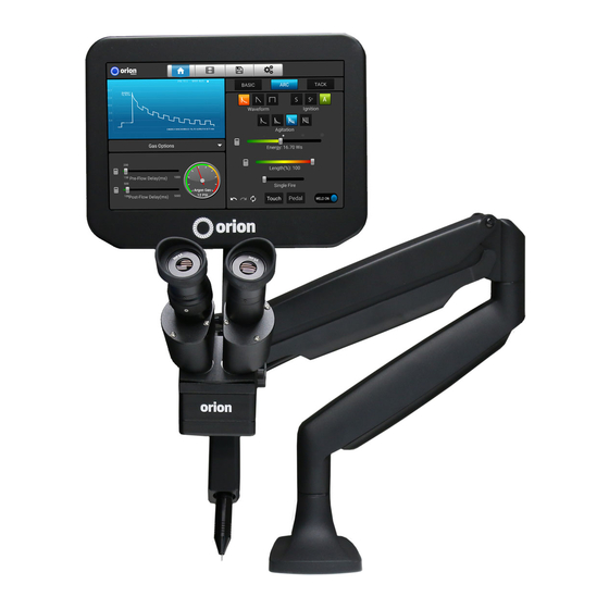
- Page 1 Orion i Series Welding System User Manual...
-
Page 2: Table Of Contents
i Series User Manual Table of Contents Chapter 1: Welder Setup and Assembly . . . . . . . . . . . . . . . . . . . . . p .3 What is in the Box . -
Page 3: Chapter 1: Welder Setup And Assembly
Diamond Dremel Disk – 1x 0 .5mm Orion Collet) (1) Fiberglass Brush BOX 2 CONTENTS (1) Cross Lock Tweezers (1) Orion i Series Microscope Arm Assembly (1) System Cover (1) Orion Safety Manual & Quick Start/ Quick Setting Guide (1) Brass Lined Pliers... -
Page 4: Attach Screen Case To Microscope
i Series User Manual Mounting Option 2 - Bolt through table Best used for tables without accessible edges . Hardware required from box: (1x) Flat Mounting Plate (letter H) (3x) Flat head screws (letter G) (1x) Long Carriage Bolt (letter F) (1x) Flat Pressure Plate (letter I) (1x) Adjustment Knob (letter J) •... -
Page 5: Arm Tension Adjustment
Arm Tension Adjustment The spring tension is factory pre-set, but should changes be desired, the spring tension can be adjusted by turning a hex screw located on the pictured arm joint . Use the included 6mm Allen wrench to make adjustments . •... -
Page 6: Adjusting The Microscope Focus
i Series User Manual Adjusting The Microscope Focus • Twist the knob on the microscope forward and backward to lower and raise the head . This will allow you to focus the microscope on the welding stylus . • Place your finger under the welding electrode to help judge the correct focus loca- tion . - Page 7 Power Supply Setup - Back Panel The cables used below can be found in the accessories box . • Plug the female end of the included power cable into the “90-250 VAC” Power port . • Connect the male end of the power cable into AC power (wall outlet) .
-
Page 8: Electrode Setup
i Series User Manual Electrode Setup The Orion welder comes standard with a 0 . 5 mm electrode collet and (5) 0 . 5 mm electrodes; and a 1 . 0 mm electrode collet and (5) 1 . 0 mm electrodes . The 1 . 0 mm electrodes are a good multipurpose electrode while the 0 . - Page 9 When To Sharpen The Electrode *Refer to Chapter 3 of the Orion Workbook for more information on electrodes . The majority of applications are best welded using a sharpened electrode tip . A sharp tip improves arc initiation and helps focus the arc properly .
-
Page 10: Shielding Gas Setup
i Series User Manual Shield Gas Setup During the pulse-arc welding process high temperature plasma quickly melts metal into a molten pool . As the weld is performed, a small amount of shielding gas is released through the weld stylus to prevent oxygen from entering the molten pool . -
Page 11: Microscope Lcd Shutter System
Microscope LCD Shutter System The microscope LCD filter shutter allows an unobstructed working view before welding and completely protects the user’s eyes during the welding process . The Orion’s internal computer verifies the microscope LCD filter shutter has been closed before allowing the weld to take place . -
Page 12: Chapter 2: User Interface Overview
i Series User Manual Chapter 2: User Interface Overview The i3 interface consists of four main “screens” that can be accessed at any time using the icons located along the top of the screen in the header area: HOME SCREEN, MEDIA SCREEN, SAVE/LOAD SCREEN, and SETTINGS SCREEN . HOME SCREEN The home screen is comprised of three separate Areas: The Waveform Graphic Area (1), The Parameter Selection Area (2), and the Mini-Screen Area (3) . -
Page 13: Parameter Selection Area
PARAMETER SELECTION AREA This area displays the buttons and sliders that can be used to control the parameters that will affect the weld . HEADER BUTTONS The three buttons at the top of the Parameter Selection Area are used to switch between control layouts and are always displayed . - Page 14 i Series User Manual being discharged than is possible with Classic . • Square - Similar to the triangle waveform, a square waveform allows users to utilize the full amount of energy over a longer period of time . The difference of this waveform compared to Classic and Triangle is the abruptness of power at the start and end of each weld .
-
Page 15: Tack Control Layout
Sustained - The Sustained option offers high levels of agitation for improved weld spot strength in some metals . The high levels of agitation energy will affect the spot size because of the extra energy used in this option . To com- pensate for this addition of agitation energy, users may need to slightly lower the overall weld energy when using this option . -
Page 16: Footer Buttons
i Series User Manual Pre-Weld delay These buttons set the time between weld trigger and weld initiation . • Short: Sets a quarter second delay before initiating the weld . • Medium: Sets a half a second delay before initiating the weld . •... -
Page 17: Media Screen
Weld Parameters • Agitation Options – adjust the agitation frequency, duty cycle, and weld per- centage . (see Agitation section of Arc Control Layout) . • Gas Options – view gas pressure gauge and adjust gas flow timing . Tapping on the gas gauge will cause a purge of the gas line . -
Page 18: Save/Load Screen
i Series User Manual Save/ Load Screen The Orion i3 can save and load your weld settings for future use . save settIngs To save your current weld parameters, press the SAVE ICON on the row of Header Buttons . The parameters will be repre- sented in the graphic waveform window . -
Page 19: Interface Options
. • Theme Selection Dropdown Box The Orion i3 has two different thematic color schemes . (Orion Blue or Sunstone Orange) Press on the desired color from the drop-down box . • Video Settings Buttons Press the “Delete Media”... -
Page 20: Gas Options
i Series User Manual • Frequency Slider Allows the users to adjust the frequency (Hz) of the agitation spikes . Typically, values of around 2500Hz are ideal for good weld results; but different metals may require different values . Higher frequencies will help break up crystalline structures during cooling . -
Page 21: System Options
• Restore All Defaults Allows the user to restore the weld settings to the original Sunstone default state . • Clear All Memory Restores all settings to default and clears memory of any saved welds, weld counts, adaptive ignition, gas pressure warn- ings and other stored information . -
Page 22: Lock Options
Press this button to lock the screen . A four-digit PIN code will need to be entered (or created if this is the first time locking the interface) . If pin is forgotten, sunstone support can be called and help you clear the pin . -
Page 23: Chapter 3: Make A Weld
UPdate vIa WIfI: 1 . Go to the Settings screen, by pressing the icon on the top right of the screen . 2 . Press the update button and choose to update via Wi-Fi . (This will update the welder to the latest software available . -
Page 24: Make A Tack Weld
i Series User Manual 4 . Look through the microscope and raise the work-piece toward the stylus until it makes contact with the electrode . 5 . Once contact is made between the electrode and grounded work-piece; the weld will automatically initiate . -
Page 25: "Aiming" The Electrode
can be important to experiment and get to know the proper settings for your specific applications . The Basic Control Layout on the HOME SCREEN can give new users an idea of where to start and helps get the ball roll- ing initially;... -
Page 26: Reading The Waveform Graph
i Series User Manual readIng the Waveform graPh The Waveform Graph is a helpful tool for understanding the things taking place during a weld . One quick look can pro- vide information such as which ignition mode is being used, which waveform has been selected, which agitation profile is being used, and the length of the energy discharge . -
Page 27: Chapter 4: Declaration Of Conformity
The total area under the graphed line (shown red here for clarity) represents the amount of energy being released into the weld . Generally speaking, the larger the area, the more heat, the larger the spot size, and the more penetration . Chapter 4. - Page 28 皕赫科学仪器(上海)有限公司 139-1685-4983...
Need help?
Do you have a question about the Orion i Series and is the answer not in the manual?
Questions and answers