Advertisement
Quick Links
4 - 1 2 6
I n s t a l l a t i o n I n s t r u c t i o n s
PARTS LIST
1
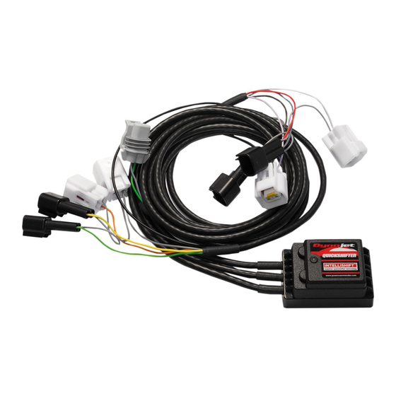
Quickshifter Stand Alone
1
Installation Guide
2
Dynojet Decal
2
Cable Tie
2
Velcro
1
Alcohol Swab
PLEASE READ ALL DIRECTIONS BEFORE STARTING INSTALLATION
2191 Mendenhall Drive North Las Vegas, NV 89081
1-800-992-4993 www.dynojet.com
Read this instruction manual before fitting and operating your product
PRECAUTIONS:
When installing this product it is advisable to position the motorcycle/vehicle so
it cannot cause injury or damage by falling over/rolling forwards or backwards.
The use of a paddock stand is ideal or if necessary chock the wheels.
Ensure that the ignition supply is switched off at all times unless instructed
otherwise within this manual.
When removing or adding electrical cables to the vehicle battery or wiring
harness always remove the negative earth cable/terminal before the positive
cable/terminal.
Replace the negative earth cable/terminal last to avoid
shorting the electrical system.
When mounting the components ensure that the units are protected from
excessive vibration and the environmental elements, and that they are securely
mounted.
Be careful not to bend or pull the wires exiting the module as this could
compromise the weather proofing causing water to enter the module.
When routing electrical cables ensure the cables cannot become trapped or
pinched which could result in malfunction and secure with cable ties where
necessary.
TROUBLESHOOTING
1. No power-up - Check for incorrect battery terminal connections, blown
fuses, poor negative battery terminal connections. Check for severed or trapped
wires.
2. No quickshifter interrupt - Check the Quickshifter is being operated above
approximatley 3000RPM. Check for correct connection of the Quickshifter
harness connectors with the yellow dots and their associated grey link wire
alignment. Verify the Quickshifter sensor output. Check for severed or trapped
wires. Check that the Quickshifter harness connectors have not been greased
as this will cause a poor electrical connection!
3. Engine misfire - Verify the control unit mounting position and check
for isolation from vibration. Check plug and play connections. Verify ignition
coil type and suitability and correct connection of the Quickshifter harness
connectors with the yellow dots and their associated grey link wire alignment.
Verify the Quickshifter sensor output.
4. For further troubleshooting contact Dynojet.
Quickshifter Installation Guide - 1
Advertisement

Related Manuals for Dynojet 4-126


Summary of Contents for Dynojet 4-126
- Page 1 Alcohol Swab connectors with the yellow dots and their associated grey link wire alignment. Verify the Quickshifter sensor output. 4. For further troubleshooting contact Dynojet. PLEASE READ ALL DIRECTIONS BEFORE STARTING INSTALLATION 2191 Mendenhall Drive North Las Vegas, NV 89081 Quickshifter Installation Guide - 1 1-800-992-4993 www.dynojet.com...
- Page 2 If your vehicle does not feature these particular ignition stick coils see Figure 2. If you are using this on a 3 cylinder model do not use the YELLOW and GREY colored leads. 4-126 www.dynojet.com Quickshifter Installation Guide - 2...
- Page 3 RPM Band#1 RPM Band#2 RPM Band#3 RPM Band#4 RPM Band#5 The RED wire of the Dynojet Quickshifter harness can be wired into the +12v wire of the coil 3000 to 5000 5000 to 7000 7000 to 9000 9000 to 11000 11000 + harness or to any switched 12v source.
- Page 4 GREEN when the sensor is in the trigger position, • This Dynojet product is covered by a 12 month warranty from the date of purchase then release the gear lever. Once you have moved the gear lever to the trigger point 4 times you’ll now against any defects in materials or workmanship.
Need help?
Do you have a question about the 4-126 and is the answer not in the manual?
Questions and answers