Advertisement
Quick Links
HermanMiller
Agile Wall installation
HZ168 and HZ172)
How to install an Agile Wall
Tools Required
Driver with a
Metric Allen Wrench
#2 Phillips Bit
Wrench
Safety Glass
Parts Included
Frame
Frame for full
height sleeves
Power Cord
Grommets
Fabric tile
Lower Fabric tile
with user power
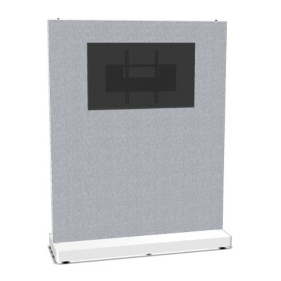
Agile Wall
(HZ138, HZ138, HZ167,
Level
Screw driver
Agile Wall Base
Counterweight
TV tile
Markerboard tile
Illustrations and specifications are based on the latest product information
available at the time of publication.
The right is reserved to make changes in design and specifications at any
time, without notice, and also to discontinue products.
For more information about our products and services or to see a list of
dealers, for assistance:
please visit us at www.hermanmiller.com or call 888-443-4357.
©2021 Herman Miller, Inc., Zeeland, Michigan Printed in U.S.A. Part No.
1BVDJ2– A
Notice:
Some of the parts have been wrapped to protect them during shipping.
Remove the plastic wrap before assembling the product.
Monitor mount
Monitor Support
plate
bracket
Shelves
Bracket
1
1BVDJ2 rev A
Support bracket
Monitor mount
support arms
Assembly Instructions
Advertisement

Related Manuals for HermanMiller HZ138


Summary of Contents for HermanMiller HZ138
- Page 1 For more information about our products and services or to see a list of dealers, for assistance: please visit us at www.hermanmiller.com or call 888-443-4357. ©2021 Herman Miller, Inc., Zeeland, Michigan Printed in U.S.A. Part No. 1BVDJ2– A...
-
Page 2: Important Safety Instructions
Warning Risk Of Injury: IMPORTANT SAFETY INSTRUCTIONS Max Load: Upper Shelf 12kg. When using an electrical furnishing, basic precautions should always be Lower Shelf 25kg. followed, including the following: Base Shelf 50kg. Read all instructions before using this furnishing. Max Load: Tech Panel 4.5kg. Each Three Panel Maximum. DANGER - To reduce the risk of electric shock always unplug this furnishing from the electrical outlet before cleaning, or relocating. - Page 3 Step 2.1: Install tiles on one side of the frame Step 1: Frame to base connection 1.1 Set the frame assembly on to the base assembly and secure 2.1.1 All tile types (fabric and markerboard) install on to the frame with (4) M8 Machine screws per side.
- Page 4 Step 4: Install Shelves 4.2 To mount the shelves place the shelf on the horizontal support 4.1 Set the frame assembly on to the base assembly and secure rail in the frame and fasten the shelf the support rail with the self with (4) M8 Machine screws per side.
- Page 5 5.4 Remove the lower rail must be temporarily removed in order remove or install the cover. 5.5 Remove the Base cover from the base. Orientation for Orientation for 2 monitors Orientation for 2 monitors 1 monitors at same height at dierent height Lower Rail 5.6 Install the counterweight blocks in the pockets.
- Page 6 5.10 Attach the bracket and AC Splitter to the rail as shown and 5.11 Run the AC cord up through the holes in each rail. secure with self tapping screws. 5.12 Run the AC cord up through the holes in frame. 5.13 Add tiles for Tv option.
- Page 7 5.14 Attach the monitor mount plate to the face of the Agile Wall tile 5.15 Attach the monitor mount plate for lower tv position bracket and fasten it to the previously installed support brackets with (4) orientation. M8 Machine screws. 5.16 Fasten the (2) monitor mount brackets to the back side of 5.17 Loosen the locking screws on the brackets so they will clear the monitor.into the threaded holes existing on the rear of the...
- Page 8 Step 6: User power installation 6.3 Fix the tiles. 6.1 If user power will be installed the lower tile on the side that will get user power will have a pre-cut opening to allow the installation of the power assembly. 6.2 Install the user power support bracket to the horizontal rail of the Agile wall frame using two machine screws..
Need help?
Do you have a question about the HZ138 and is the answer not in the manual?
Questions and answers