Table of Contents
Advertisement
Quick Links
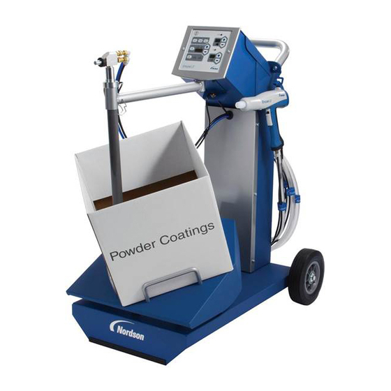
Encore™ XL Powder
Feed Center
Customer Product Manual
Document Number
1607027-01
Issued 12/21
For parts and technical support, call the Industrial Coating
Systems Customer Support Center at (800) 433-9319 or
contact your local Nordson representative.
This document is subject to change without notice.
Check
http://emanuals.nordson.com
for the latest version.
NORDSON CORPORATION • AMHERST, OHIO • USA
Advertisement
Table of Contents
Troubleshooting

Related Manuals for Nordson Encore XL Powder


Summary of Contents for Nordson Encore XL Powder
- Page 1 For parts and technical support, call the Industrial Coating Systems Customer Support Center at (800) 433-9319 or contact your local Nordson representative. This document is subject to change without notice. Check http://emanuals.nordson.com for the latest version. NORDSON CORPORATION • AMHERST, OHIO • USA...
- Page 2 Nordson Corporation welcomes requests for information, comments, and inqui- This is a Nordson Corporation publication which is protected by copyright. ries about its products. General information about Nordson can be found on the Original copyright date 2021. No part of this document may be photocopied,...
-
Page 3: Table Of Contents
Pump Flow and Atomizing Air Tubing ................... Powder Feed Hose Connections ....................Hose and Tubing Routing ......................Lance Fluidizing Air Connection ....................Reclaim and Virgin Powder Feed Options ..................Lift Cylinder Proximity Switch Adjustment ..................Level Sensor Position Adjustment ....................3-10 1607027-01 ©2021 Nordson Corporation... - Page 4 Color Change Operation ........................ Color Change Procedure ......................Shutdown ............................Daily Maintenance ......................... Periodic Maintenance ........................Emptying the Waste Hopper ......................Troubleshooting ..........................Purge Position Sensor and Stop Bolt Realignment ..............Filter Section Problems ........................ 7-10 1607027-01 ©2021 Nordson Corporation...
- Page 5 8-22 Removing the Cartridge Filter ..................... 8-22 Installing the Cartridge Filter ....................... 8-22 Final Filter Replacement ......................8-24 Pulse Valve Replacement ......................8-25 Collector Fluid Plate Replacement ....................8-26 Vibratory Table Isolator Mount Replacement ................8-28 1607027-01 ©2021 Nordson Corporation...
- Page 6 Controller and Cable Installation ....................10-5 Operation ............................ 10-6 Troubleshooting .......................... 10-6 Fault Conditions ........................10-6 Electrical Troubleshooting Procedures ..................10-7 VIBRASONICS/POWER Indicator Troubleshooting ..............10-8 Vibrasonic System Parts ......................10-9 Pneumatic and Electrical Diagrams ..................11-1 1607027-01 ©2021 Nordson Corporation...
- Page 7 Change Record Change Record Revision Date Change 12/21 Initial Release 1607027-01 ©2021 Nordson Corporation...
- Page 8 Change Record 1607027-01 ©2021 Nordson Corporation...
-
Page 9: Safety
Intended Use Use of Nordson equipment in ways other than those described in the documentation supplied with the equipment may result in injury to persons or damage to property. Some examples of unintended use of equipment include: •... -
Page 10: Personal Safety
• Clean, maintain, test, and repair equipment according to the instructions in your equipment documentation. • Use only replacement parts that are designed for use with original equipment. Contact your Nordson representative for parts information and advice. 1607027-01 © 2021 Nordson Corporation... -
Page 11: Grounding
• Disconnect and lock out system electrical power. Close hydraulic and pneumatic shutoff valves and relieve pressures. • Identify the reason for the malfunction and correct it before restarting the system. Disposal Dispose of equipment and materials used in operation and servicing according to local codes. 1607027-01 © 2021 Nordson Corporation... - Page 12 1-4 Safety 1607027-01 © 2021 Nordson Corporation...
-
Page 13: Overview
® to transport over-sprayed powder from the powder recovery system to the feed center, and an optional HDLV pump to transport virgin powder to the system as needed. Figure 2-1 Powder Feed Center 1607027-01 © 2021 Nordson Corporation... -
Page 14: Introduction Cont
The reclaim and virgin HDLV transfer pumps are purged manually when the operator is ready. The Encore XL Powder Feed Center has an integrated air extraction system that provides a constant airflow through the feed center enclosure, preventing powder from escaping into the spray room. - Page 15 10. Enclosure 16. Final filters shown) 11. Purge manifold 17. Blow-down timer 5. Fluidizing air regulators 18. Blow-down solenoids NOTE: Refer to Operation section for a description of the feed center controls. 1607027-01 © 2021 Nordson Corporation...
-
Page 16: Feed Center Control Panel
Right: On On: Complete Color Change Enable Exhaust Fan Left: Off Right: On Emergency Stop Final Filter Fault Indicator (Amber) Pressed In: Stop Rotate and Pull Out: Start Vibratory Table Motor Control Left: Off Right: On 1607027-01 © 2021 Nordson Corporation... -
Page 17: Lance Assemblies
The cylinder also uses a balancing air circuit, which applies air pressure to both sides of the piston to prevent lurching when restarting motion after a locked stop. 1607027-01 © 2021 Nordson Corporation... -
Page 18: Lift Assembly (Contd)
NINE-STATION CONTROL MANIFOLD Figure 2-5 Lance Lift Assembly 1. Flow control valves 4. Locking mechanism 7. Carriage stop 2. Proximity sensors 5. Support block/flange 8. Linear V-guide 3. Lift cylinder 6. Lift plate with wheels 1607027-01 © 2021 Nordson Corporation... -
Page 19: Lance Lift Operation
• Lance lock solenoid valve energized, lock air line pressurized, cylinder rod unlocked. • Lance down solenoid valve energized, venting line to lance up regulator and bottom of piston. Pressure to lance down regulator and top of piston forces piston down. 1607027-01 © 2021 Nordson Corporation... -
Page 20: Level Sensor Modules
The box proximity sensor on the lift cylinder prevents the lance from crashing into the bottom of the box. See Figure 2-6. To adjust the position of each level sensor for the application, loosen the clamp screw (4) with a hex key. 1607027-01 © 2021 Nordson Corporation... - Page 21 Overview Figure 2-6 Level Sensor Modules 1. Level sensor 3. Clamp 4. Clamp screw 2. Bracket 1607027-01 © 2021 Nordson Corporation...
-
Page 22: Purge Manifolds
Retract (Unclamp): The air line to the retract flow control valve (1) at the rod end of the cylinder is pressurized with line air pressure, forcing the cylinder piston and rod into the cylinder. The extend air line is vented. 1607027-01 © 2021 Nordson Corporation... - Page 23 Figure 2-7 Purge Manifold Assembly (4 lance assembly shown with cylinder and latches in clamping position) 1. Retract flow control valve 4. Extend flow control valve 6. Lance guides 2. Piston proximity sensors 5. Latches 7. Purge Manifold 3. Latch cylinder 1607027-01 © 2021 Nordson Corporation...
-
Page 24: Sieve
10. Ground clip 2. Powder inlet stubs (4) 6. Powder purge ports 11. Latches 3. Sieve lid 7. Vibration isolators 12. Screen gasket 4. Vibrator motor 8. Sieve pan discharge chute 13. Sieve screen 9. Sieve ring 1607027-01 © 2021 Nordson Corporation... -
Page 25: Pneumatic Panel Components
4. Control manifold 6. Lance DOWN regulator/gauge 2. Air manifold 5. Lance UP regulator/gauge 7. Purge clamp regulator/gauge 3. Interlock valve NOTE: Refer to Setup and Operation section for air pressure and control settings and usage. 1607027-01 © 2021 Nordson Corporation... -
Page 26: Control Manifold Functions
Lance Lock (energized to unlock cylinder, vented to lock cylinder) SOL 331 Purge Clamp (extend/retract) SOL 342 HDLV Virgin Pump Purge SOL 338 HDLV Virgin Pump On SOL 340 HDLV Reclaim Pump Purge SOL 336 HDLV Reclaim Pump On SOL 329 Damper (open/closed) 1607027-01 © 2021 Nordson Corporation... -
Page 27: Optional Hd Tube Assembly
(2). The quick-disconnect fitting on the top of the siphon tube (1) accommodates 8-mm tubing. NOTE: This option can only be used with fluidized hoppers. Figure 2-11 Siphon Tube Assembly (Optional) 1. Siphon tube 2. Spring clips 3. Bracket 1607027-01 © 2021 Nordson Corporation... -
Page 28: Optional Powder Hoppers
(22.7 kg) 75 lb (34 kg) 16 in. (411 mm) 17.5 in. (444 mm) 18 in. 18 in. 36 in. (457 mm) (457 mm) (914 mm) 18 in. (457 mm) Figure 2-12 Optional Fluidizing Feed Hoppers 1607027-01 © 2021 Nordson Corporation... -
Page 29: Specifications
Fully Equipped: 2900 lb (1316 kg) 82.5 in. (2096 mm) 71 in. (1803 mm) 73 in. (1854 mm) 107 in. (2718 mm) 31 in. (787 mm) 80.75 in. (2051 mm) Figure 2-13 Feed Center Dimensions 1607027-01 © 2021 Nordson Corporation... -
Page 30: Electrical Requirements
The air must be clean and dry. Use a dedicated, refrigerated or regenerative-desiccant air dryer that can produce a 3 °C (38 °F) or lower dewpoint at 6.9 bar (100 psi), and filter/ separators with automatic drains. 1607027-01 © 2021 Nordson Corporation... -
Page 31: Air Pressures
381 mm (15 inch) Sieve: 864 Micron, 20 mesh without ultrasonics (standard) 381 Micron, 40 mesh without ultrasonics 234 Micron, 60 mesh, without ultrasonics 178 Micron, 80 mesh with ultrasonics 140 Micron, 100 mesh with ultrasonics 1607027-01 © 2021 Nordson Corporation... -
Page 32: Air Filtration
Any powder that remains in the air that passes through the cartridge filters is collected on the final filters (2) before the air returns to the spray room. Figure 2-14 Powder Feed Center Air Filtration 1. Exhaust fan 3. Pulse valves 5. Waste hopper 2. Final filters 4. Cartridge filters 1607027-01 © 2021 Nordson Corporation... -
Page 33: Unpacking
Unpacking Upon receipt, unpack the feed center carefully to avoid damage. Report any damage immediately to the shipper and to your Nordson representative. Save packing materials for possible later use, or dispose of properly according to local regulations. Preparing for Installation Position the feed center on a level floor according to the system layout drawing supplied by Nordson application engineering. -
Page 34: Electrical Connections
Before starting the feed center, turn on the feed center power and refer to the Setup procedures to program the controls for the application. This should be performed only by a Nordson field engineer, or a qualified customer controls engineer. External Powder Hose and Air Connections Air Connection: JIC hose or NPT (National Pipe Thread) The feed center is supplied with a 1-in. -
Page 35: Powder Pump Installation And Connections
Install the retaining rods into the brackets to lock the pumps in place. The pump connections are application specific; refer to your system drawings for the correct connections. 1607027-01 © 2021 Nordson Corporation... -
Page 36: Pump Flow And Atomizing Air Tubing
Use the bar (3) to support tubing and hoses. Level Sensor (Hopper) Level Sensor (Box) Atomizing Air (8-mm Blue) Pump Retainer Flow-rate Air (8-mm Black) Pump Figure 3-2 Pump, Air Tubing, and Powder Feed Hose Installation 1607027-01 © 2021 Nordson Corporation... -
Page 37: Lance Fluidizing Air Connection
Figure 3-3 Pump, Powder Feed Hose, and Air Tubing Connections to Lance Assembly 1. Pumps 4. Flow-rate air tubing (black) 7. Powder feed hose 2. Retaining rod 5. Atomizing ar tubing (blue) 8. Air multi-tube gasket 3. Bar 6. Powder hose grommet 9. Fluidizing air 1607027-01 © 2021 Nordson Corporation... -
Page 38: Reclaim And Virgin Powder Feed Options
6-mm tubing to the virgin pump purge valve. The valve opens and allows air at line pressure to flow through the pump and the 16-mm suction and delivery powder tubing to clean them. The purged powder is dumped into the feed center exhaust duct to the afterfilter. 1607027-01 © 2021 Nordson Corporation... - Page 39 RECLAIM POWDER 6 mm TRANSFER PAN FLUIDIZING VIRGIN POWDER SOURCE VIRGIN POWDER (BOX OR DRUM) 16 mm FEED CENTER SIEVE BULK FEED SYSTEM (OPTIONAL) Figure 3-4 Single Reclaim Pump and Optional Virgin Powder Connections and Equipment 1607027-01 © 2021 Nordson Corporation...
- Page 40 6 mm RECLAIM PUMP PANEL 16 mm 8 mm 8 mm 8 mm 6 mm TRANSFER PAN FLUIDIZING 16 mm 6 mm 16 mm FEED CENTER SIEVE Figure 3-5 Dual Reclaim Pump Connections and Equipment 1607027-01 © 2021 Nordson Corporation...
-
Page 41: Lift Cylinder Proximity Switch Adjustment
Slide the switch up or down until the switch LED turns on. Mark the positions at which the switch LED turns on in both directions, then secure the switch midway between the on positions. 1607027-01 © 2021 Nordson Corporation... -
Page 42: Level Sensor Position Adjustment
4. Powder used during delay 7. Total lance travel length 2. Hopper proximity switch stop 5. Delay runs out, virgin pump starts 8. Box proximity switch stop 3. Low powder delay start 6. Box level sensor stop 1607027-01 © 2021 Nordson Corporation... -
Page 43: Setup
The virgin transfer pump must be Low Powder Alarm on. If powder is detected before the timer minutes Delay runs out, the timer is cancelled. The buzzer can be silenced by switching Gun Purge on momentarily. Continued... 1607027-01 © 2021 Nordson Corporation... -
Page 44: Feed Center Function Settings (Contd)
The purge cycle Bank stops when the duration timer runs out. 45.00 seconds SCREEN 7 Configures the gun purge bank quantity per system. The maxi- Gun Purge mum number of gun purge banks Bank Quantity is three. 1607027-01 © 2021 Nordson Corporation... -
Page 45: Changing Function Values
7. Press the the OK key to enter the value. 8. Make additional changes to the same page by moving the cursor as described in steps 4−7. 9. When data changes to the page are complete, press the ESC key twice. 1607027-01 © 2021 Nordson Corporation... -
Page 46: Level Sensor Programming
Yellow and Flashing quickly Short circuit of the switching output Normal function check; level sensor probe is Lit temporarily approaching the full state Lit continuously Level sensor probe is dirty or out of adjustment. 1607027-01 © 2021 Nordson Corporation... -
Page 47: Empty (No Powder) Programming
LED turns back on continuously, the level sensor probe is ready for operation. Press the programming button for 10 seconds. After 10 seconds, all Unlocking LEDs turn off, indicating that the level sensor probe is unlocked. 1607027-01 © 2021 Nordson Corporation... -
Page 48: Operational Faults (Red Led Flashing)
LED Ring OUT OFF Programming OUT ON Button Programming Button Figure 4-3 Programming the Two Button Level Sensor Probe LED Functions LED Color Status Means Green Material not detected Yellow Material detected 1607027-01 © 2021 Nordson Corporation... -
Page 49: Empty (No Powder) Programming
• Empty programming was done while the probe was in the powder, or Full programming was done while the probe was out of the powder. • During Empty programming, the distance between the probe and the powder was too short. 1607027-01 © 2021 Nordson Corporation... -
Page 50: Air Pressure Settings
Feed Hopper Fluidizing 0.03−0.06 Mpa 0.3−0.7 bar (5−10 psi) (see Note) Lance Fluidizing 0.03−0.06 Mpa NOTE: Adjust fluidizing air as needed. Powder should be gently boiling, without geysering. Figure 4-4 Pneumatic Controls (1 of 2) 1607027-01 © 2021 Nordson Corporation... - Page 51 Setup Figure 4-5 Pneumatic Controls (2 of 2) 1607027-01 © 2021 Nordson Corporation...
-
Page 52: Typical Operating Settings
You may need to adjust the settings if the feed center’s cartridge filters are not being pulsed sufficiently. Table 4-2 Table 3-3 Typical Pulse Valve Timer Board Settings Timer Setting Filter Pulse On Duration 0.07 seconds Filter Pulse Off Duration 10 minutes 1607027-01 © 2021 Nordson Corporation... - Page 53 Operation Section 5 Operation WARNING: Allow only qualified personnel to perform the following tasks. Follow the safety instructions in this document and all other related documentation. 1607027-01 © 2021 Nordson Corporation...
-
Page 54: Controls
12. Exhaust Fan Turns exhaust fan on and off. Switch will illuminate when On. Off: Normal operation, no fault. 13. Final Filter Fault Indicator On: High pressure sensed by final filter sensor. Exhaust fan will turn off. 1607027-01 © 2021 Nordson Corporation... -
Page 55: Feed Center Operation
The buzzer can be silenced by: • filling the feed hopper until the powder contacts the level sensor. • momentarily turning on gun purge. • turning the virgin transfer pump off. 1607027-01 © 2021 Nordson Corporation... -
Page 56: Transfer Pump Manual Purging
Make sure all settings in the Setup section of this manual have been completed before starting up the system for the first time. 1. Turn on power and air to the feed center, if not already on. 2. Turn on the afterfilter exhaust fan. 1607027-01 © 2021 Nordson Corporation... - Page 57 Turn on the reclaim transfer pump and enable the virgin transfer pump. 9. Turn on the sieve. 10. Turn on the spray guns and start spraying powder. Make sure everything is working correctly before starting production. 1607027-01 © 2021 Nordson Corporation...
-
Page 58: Color Change Operation
• Color Change request signal OFF detected. • Turn OFF Reclaim Pump Purge switch. • Gun movers return to normal operation mode. • Color Change Indicator turns off. • Color Change signal turns off. Figure 5-2 Color Change Sequence 1607027-01 © 2021 Nordson Corporation... -
Page 59: Color Change Procedure
Meanwhile, another operator cleans the booth and cyclone. The recommended sequence of steps is provided in the color change charts furnished by Nordson, but can be modified as desired depending on the customer needs and requirements. Shutdown 1. - Page 60 5-8 Operation 1607027-01 © 2021 Nordson Corporation...
-
Page 61: Daily Maintenance
Enclosure Clean the interior and exterior of the feed center. Check all equipment ground connections. Check the seals around the cartridge filters. If the cartridge filters are not sealing properly, Cartridge Filters tighten them. 1607027-01 © 2021 Nordson Corporation... -
Page 62: Periodic Maintenance
System Grounds Refer to Grounding in the Safety section of this manual and to publication number TCTT-06- 3881 on the Nordson emanuals web site (http://emanuals.nordson.com/finishing) for more information on powder coating system grounding. Pressurize the system and listen for air leaks. Replace or repair any leaking tubing or Air Tubing fittings. -
Page 63: Emptying The Waste Hopper
6. When the transfer pump is not drawing any more powder out of the waste hopper, touch the WASTE PUMPS STOP button. NOTE: The waste transfer process will automatically stop after several minutes. The duration of the waste transfer process may be changed on the Feed Center Setup menu. 1607027-01 © 2021 Nordson Corporation... - Page 64 6-4 Maintenance Figure 6-1 Emptying the Waste Hopper 1. Vent hose 3. Scrap drum with lid 5. Transfer pump 2. 3/4-in. Transfer hoses 4. Ground clamp 6. Feed center vent stub 1607027-01 © 2021 Nordson Corporation...
-
Page 65: Troubleshooting
If you cannot solve your problem with the information in this manual or related equipment manuals, contact the Nordson Industrial Coating Systems Customer Support Center at (800) 433−9319 or your local Nordson representative. - Page 66 Check the wiring from the feed center panel to the solenoid valve defective assembly in the feed center blow-down housing. Fluidizing air regulator Check the fluidizing air regulator. defective Continued... 1607027-01 © 2021 Nordson Corporation...
- Page 67 Check the motor and electrical connections. Sieve motor overload Check the motor internal weights for proper adjustment. Make sure the overload protector is set to the proper limit. Reset the overload. Sieve motor failed Replace the sieve motor. Continued... 1607027-01 © 2021 Nordson Corporation...
- Page 68 Problem with transfer pump with electric timing valve manual 1619979 and Pump pump controls or pump Station manual 1620734. Level sensor failed or Check the level sensor and wiring. Repair or replace as needed. wiring defective Continued... 1607027-01 © 2021 Nordson Corporation...
- Page 69 Purge air process valve in pump station. Check process valve operation. Check air valve or pilot air tubing supply to process valve. Repair or replace as needed. Refer to defective pump station manual 1620734. Continued... 1607027-01 © 2021 Nordson Corporation...
- Page 70 PLC not initiating color Check PLC operation. Contact your Nordson representative or change sequence. technical support center for help. Encore Engage system tracks parts through booth and will Parts still in booth delay color change start until parts clear booth.
- Page 71 Oscillator gets stop command from gun positioner controller. cycle started, gun Refer to your system electrical drawings. positioner stopped Contact Nordson technical support. at forward limit Oscillator not stopped USA only − Oscillator bottom of stroke sensor not sending signal switch to main system panel.
-
Page 72: Purge Position Sensor And Stop Bolt Realignment
With the LED illuminated, tighten the sensor bracket. 6. Use the LANCE UP/DOWN buttons to make sure that the sensor LED illuminates when the pickup plates engage the purge manifolds. Readjust the stop bolt and sensor if necessary. 1607027-01 © 2021 Nordson Corporation... - Page 73 Figure 7-1 Purge Position Sensor and Stop Bolt Realignment 1. Hopper stop sensor 4. Sensor LED 7. Stop bolt 2. Box stop sensor 5. Linear slide 8. Pickup plate 3. Purge position sensor 6. Jam nut 9. Purge manifold 1607027-01 © 2021 Nordson Corporation...
-
Page 74: Filter Section Problems
Refer to Cartridge Filter Replacement in the Repair section for instructions. 4. Fan stops Final filter pressure too The final filter pressure switch is detecting abnormal pressure at unexpectedly high the final filters. Refer to Problem 3 in this table. 1607027-01 © 2021 Nordson Corporation... -
Page 75: Repair
This section contains basic repair instructions for the powder feed center. Repair procedures for other system components are covered in their own, separate manuals. Contact your Nordson representative about any powder feed center repair procedures that are not covered in this section. -
Page 76: Latch Pawl Replacement
7. Re-install the hopper/box table on the isolation mounts, and then, if used, pull the vibrator motor cable back into the control cabinet. Leave enough slack in the cable to avoid any strain on it, then tighten the cord grip. 1607027-01 © 2021 Nordson Corporation... -
Page 77: Latch Replacement
2. Slide the new latch on the hex shaft so that the bottom of the latch body is parallel to the surface of the mounting block. 3. Position the latch body over the tapped holes in the mounting block and install the four socket screws. 1607027-01 © 2021 Nordson Corporation... -
Page 78: Latch Installation (Cont)
If the pawl binds against the sides of the body, loosen the four latch mounting screws, then push outwards on the sides of the latch body while re-tightening the screws. Gap should be equal both sides Figure 8-4 Lever Position − Step 4 1. Yoke 2. Lever 3. Hex shaft 1607027-01 © 2021 Nordson Corporation... -
Page 79: Latch Pawl Adjustment
However, do not do so if this allows the latch to go over-center when the lance is clamped down. 3 Pins at end of travel, over-center Figure 8-5 Pawl Adjustment − Latch Shown Over-Center 1. Pawl mount 2. Pawl 3. Pins 1607027-01 © 2021 Nordson Corporation... -
Page 80: Clamping Cylinder Replacement
Note the position where the LED turned on, then continue sliding it in the same direction until the LED turns off. c. Position the switch in the midpoint between LED off positions and tighten the clamp screw to secure it in place. 1607027-01 © 2021 Nordson Corporation... -
Page 81: Clamping Cylinder Replacement (Contd)
9. Extend flow control valve 2. Clevis pins 6. Retract proximity switch (LS404) 10. Cylinder assembly 3. Delrin spacer 7. Extend proximity switch (LS403) 11. Manifold shaft 4. Lever 8. Retract flow control valve 12. Cylinder adapter spacer 1607027-01 © 2021 Nordson Corporation... -
Page 82: Lift Cylinder Replacement
7. Remove the four M8x30 socket-head screws from the bottom of the flange. 8. Lift the cylinder up and out of the enclosure. 9. Remove the clevis and lock nut, flat washer, and sleeve from the cylinder. Save these parts for re-use. 1607027-01 © 2021 Nordson Corporation... - Page 83 LS308 Purge To Up Regulator To Lock Solenoid #7 (6-mm blue) SOL326 (6-mm blue) M8x30 Sockethead Cap Screws M10x20 Sockethead Cap Screws Flange Washer Sleeve Lock Nut Clevis Pin Clevis Carriage Figure 8-8 Lift Cylinder Replacement 1607027-01 © 2021 Nordson Corporation...
-
Page 84: Lift Cylinder Installation
Box switch (LS307) and the Hopper switch (LS306). 12. Raise and lower the lance assembly and adjust the cylinder flow control valves for 6 seconds full travel in each direction. 1607027-01 © 2021 Nordson Corporation... -
Page 85: Cylinder Cushion Stop Adjustment
4. Loosen the four screws securing the lance arm to the lift carriage plate, just enough to move the lance arm. The lance arms must not sag. Step 4 Step 3 Step 2 Figure 8-9 Lance Adjustment Steps 2−4 1607027-01 © 2021 Nordson Corporation... -
Page 86: Lance Assembly/Purge Manifold Alignment (Contd)
Carriage Jam Nut Stop Bolt Quad-Ring Seals Figure 8-10 Stop Bolt Adjustment 7. Turn the Purge Control switch to the Internal Gun Purge position. The lance will be clamped into place. 1607027-01 © 2021 Nordson Corporation... - Page 87 If air leaks from the seals, loosen the latch pawl screws and move the pawls down one notch for a tighter clamp force. Refer to page 8-4 for the pawl adjustment procedure. 1607027-01 © 2021 Nordson Corporation...
-
Page 88: Feed Hopper Fluidizing Plate Replacement
6. Re-assemble the body, fluidizing plate, and plenum with the screws, washers, and nuts. CAUTION: Do not overtighten the nylon screws. Overtightening the screws will result in stripped threads and possible air or powder leaks. 1607027-01 © 2021 Nordson Corporation... - Page 89 Repair 8-15 Figure 8-12 75-lb Feed Hopper Fluidizing Plate Replacement 1. Body 4. Plenum 6. Nylon flat washers 2. Fluidizing plate 5. Nylon screws (M8 x 40 mm) 7. Nylon hex nuts (M8) 3. U-gasket 1607027-01 © 2021 Nordson Corporation...
-
Page 90: 50-Lb Feed Hopper Fluidizing Plate Replacement
Do not overtighten the nylon screws. Overtightening the screws will result in stripped threads and possible air or powder leaks. Figure 8-13 50-lb Feed Hopper Fluidizing Plate Replacement 1. Body 3. Plenum 5. Nylon screws 2. Fluidizing plate 4. O-ring gaskets 1607027-01 © 2021 Nordson Corporation... -
Page 91: Vibratory Table Motor Weight Adjustment
VIBRATOR, 230/460V, 3PH/60Hz (standard) Oli−Wamgroup/MVE 60/3 1602896 VIBRATOR, 330/575V, 3PH/60Hz Oli−Wamgroup/MVE 60/3 1602893 VIBRATOR, 220/380V, 3PH/60Hz Oli−Wolong/MVE 60/3 1602895 VIBRATOR, 200/400V, 3PH/50Hz, ATEX Oli−Wamgroup/MVE 60/3 1602894 VIBRATOR, 220/380V, 3PH/50Hz Oli−Wolong/MVE 60/3 1602892 VIBRATOR, 240/415V, 3PH/50Hz Oli−Wolong/MVE 60/3 1607027-01 © 2021 Nordson Corporation... -
Page 92: 60Hz Motor Weight Adjustment
Use another wrench to unscrew the remaining nut. Remove the weight blades from the end of the shaft. Step 1 Step 2 - 3 Step 4 Step 4 Figure 8-14 Vibrator Weight Adjustment, 60Hz, Steps 1−4 1607027-01 © 2021 Nordson Corporation... - Page 93 7. Install the end caps with the flat area on the cap aligned with the flat area on the mounting flange. 8. Tighten the screws to 4 ft-lb. Step 5 Step 5 - 6 Step 7 Step 7 - 8 FLAT AREAS ALIGNED FLAT AREA Figure 8-15 Vibrator Weight Adjustment, 60Hz, Steps 5−8 1607027-01 © 2021 Nordson Corporation...
-
Page 94: 50Hz Motor Weight Adjustment
Use another wrench to unscrew the remaining nut. Remove the weight blades from the end of the shaft. Step 1 Step 2 - 3 Step 4 Step 4 Figure 8-16 Vibrator Weight Adjustment, 50Hz, Steps 1−4 1607027-01 © 2021 Nordson Corporation... - Page 95 7. Install the end caps with the flat area on the cap aligned with the flat area on the mounting flange. 8. Tighten the screws to 4 ft-lb. Step 5 Step 5 - 6 Step 7 Step 7 - 8 FLAT AREA FLAT AREAS ALIGNED Figure 8-17 Vibrator Weight Adjustment, 50Hz, Steps 5−8 1607027-01 © 2021 Nordson Corporation...
-
Page 96: Cartridge Filter Replacement
8. Tighten the nut until the mounting and centering brackets are touching. This will compress the gasket (11) and seal the cartridge against the mounting plate. 9. Install the pulse valve and cartridge filter access panels (1, 2). 1607027-01 © 2021 Nordson Corporation... - Page 97 1. Cartridge filter access panel 5. Flat washer 9. Centering bracket 2. Pulse valve access panel 6. Mounting bracket 10. Cartridge filter 3. Nut 7. Mounting plate 11. Gasket 4. Lock washer 8. Draw rod 1607027-01 © 2021 Nordson Corporation...
-
Page 98: Final Filter Replacement
5. Place the new final filter into the powder feed center. 6. Install the final filter brackets. 7. Tighten the bracket nuts to compress the final filter evenly on all four sides. Figure 8-19 Final Filter Replacement 1607027-01 © 2021 Nordson Corporation... -
Page 99: Pulse Valve Replacement
9. Connect the air tubing to the elbow. 10. Install the pulse valve access panel and turn on system air pressure. Figure 8-20 Pulse Valve Replacement 1. Nipple 3. Pulse valve 5. Pulse valve access panel 2. Elbow 4. Nozzle 1607027-01 © 2021 Nordson Corporation... -
Page 100: Collector Fluid Plate Replacement
3. Turn off and lock out power to the powder feed center. 4. Remove the jack screws (2) from the clamp brackets (3). Figure 8-21 Waste Hopper Fluid Plate Replacement (1 of 2) 1. Cartridge filter access panel 2. Jack screw 3. Clamp bracket 1607027-01 © 2021 Nordson Corporation... - Page 101 19.63 in. (499 mm) Bottom of Fluid Plate Apply bond adhesive to seams of gaskets. Figure 8-22 Waste Hopper Fluid Plate Replacement (2 of 2) 4. Bearing plate 6. Fluid plate 7. Gaskets 5. Hex screws 1607027-01 © 2021 Nordson Corporation...
-
Page 102: Vibratory Table Isolator Mount Replacement
1-4 in reverse to install the vibratory table into the feed center. Figure 8-23 Vibratory Table Isolator Mount Replacement (Side View of Vibratory Table) 1. Screws 4. Vibratory table 7. Hex screws 2. Lock washers 5. Nuts 8. Isolator mounts 3. Vibrator motor 6. Washers 1607027-01 © 2021 Nordson Corporation... -
Page 103: Parts
A dash (—) is used when the part number applies to all parts in the illustration. The number in the Part column is the Nordson Corporation part number. A series of dashes in this column (- - - - - -) means the part cannot be ordered separately. -
Page 104: Powder Feed Centers
9-2 Parts Powder Feed Centers See Figure 9-1 and the following parts list. Figure 9-1 Powder Feed Center Parts 1607027-01 © 2021 Nordson Corporation... -
Page 105: System Assemblies
SYSTEM ASSEMBLY, powder feed center, Encore XL, 4 lance, left-hand 1607653 SYSTEM ASSEMBLY, powder feed center, Encore XL, 2 lance, right-hand 1607654 SYSTEM ASSEMBLY, powder feed center, Encore XL, 3 lance, right-hand 1607655 SYSTEM ASSEMBLY, powder feed center, Encore XL, 4 lance, right-hand 1607027-01 © 2021 Nordson Corporation... -
Page 106: Lift Assembly Parts
9-4 Parts Lift Assembly Parts See Figure 9-2 and the following parts list. Figure 9-2 Lift Assembly Parts 1607027-01 © 2021 Nordson Corporation... - Page 107 • ELBOW, male, 6 mm tube x 1/8 BSPT 1103505 • SWITCH, cylinder proximity 1103937 • FITTING, flow control, 6 mm T x 3/8 G 1103505 • CYLINDER, locking, 63 x 750 982043 • SCREW, socket, M 10 x 20, black 1607027-01 © 2021 Nordson Corporation...
-
Page 108: Lance Assembly Parts
• SCREW, socket, M10 x 25 mm −−−−−− • WASHER, lock, split, M8, steel, zinc 1095926 PUMP ASSEMBLY, corona, Encore Gen II, pkg NOTE: A. Refer to pump manual for repair parts. Pumps must be ordered separately. AR: As Required 1607027-01 © 2021 Nordson Corporation... -
Page 109: Fluidizing Latch Block Kits
−−−−−− • NUT, air passage blanking −−−−−− • SLEEVE, locating, global PFC lance 1102804 KIT, fluidizing tube, PFC 940142 • O-RING, silicone, 0.489 in. ID x 0.07 in. wide −−−−−− • TUBE, fluidizing, stainless steel 1607027-01 © 2021 Nordson Corporation... -
Page 110: Lance Port Plug Module
• WASHER, sealing, lance plug, global PFC −−−−−− • SLEEVE, lance plug, global PFC −−−−−− • ROD, threaded, lance plug, GPFC −−−−−− • PLUG, lance, global PFC −−−−−− • SCREW, set, cup point, M12 x 1.75, 12mm long, stainless steel 1607027-01 © 2021 Nordson Corporation... -
Page 111: Level Sensor Module
1023925 • CABLE, 4 pin, M12 connector, 5 meters long −−−−−− • SCREW, socket, M5 x 16, zinc −−−−−− • NUT, lock, M5 −−−−−− • BRACKET, level sensor 1100076 • SUPPORT, 16 mm shaft, clamping 1607027-01 © 2021 Nordson Corporation... -
Page 112: Encore Siphon Tube Module
See Figure 9-7 and the following parts list. Use this module to provide powder to Prodigy or Encore HD manual guns through 8-mm tubing. Use existing fasteners Figure 9-7 Prodigy/Encore HD Siphon Tube Module Parts 1607027-01 © 2021 Nordson Corporation... - Page 113 • SIPHON TUBE, global PFC −−−−−− • SCREW, cap, button head socket, M4, 10 mm, steel, zinc plated −−−−−− • HOLDER, tool, spring type −−−−−− • NUT, lock, nylon, M4 steel, zinc −−−−−− • BRACKET, siphon, global PFC 1607027-01 © 2021 Nordson Corporation...
-
Page 114: Purge Manifold And Pneumatics
Purge Manifold Assembly See Figure 9-8 and the following parts list. Quantities listed as As Required are dependent on the number of purge manifolds for two, three, or four lance. Figure 9-8 Purge Manifold Module Parts 1607027-01 © 2021 Nordson Corporation... - Page 115 ELBOW, push in, 0.50 RPT x 16 mm tube −−−−−− WASHER, lock, internal/external tooth, 5/16 in. −−−−−− SCREW, pan, slotted, M5 x 20, brass −−−−−− WASHER, lock, external, M5, steel, zinc −−−−−− WASHER, flat, M5, brass AR: As Required 1607027-01 © 2021 Nordson Corporation...
-
Page 116: Purge Valve Assembly − Two Lance Configuration
• CONNECTOR, male, 16 m T x 1/2 RPT, with seal 1082873 • PLUG, pipe, socket, flush, R3/8, nickel 1100283 • VALVE, solenoid, air, 2 x 3, G.5 1607046 • CABLE, valve, purge, 10 m 1607027-01 © 2021 Nordson Corporation... -
Page 117: Purge Valve Assembly − Three Lance Configuration
• CONNECTOR, male, 16 m T x 1/2 RPT, with seal 1082873 • PLUG, pipe, socket, flush, R3/8, nickel 1100283 • VALVE, solenoid, air, 2 x 3, G.5 1607046 • CABLE, valve, purge, 10 m 1607027-01 © 2021 Nordson Corporation... -
Page 118: Purge Valve Assembly − Four Lance Configuration
• CONNECTOR, male, 16 m T x 1/2 RPT, with seal 1082873 • PLUG, pipe, socket, flush, R3/8, nickel 1100283 • VALVE, solenoid, air, 2 x 3, G.5 1607046 • CABLE, valve, purge, 10 m 1607027-01 © 2021 Nordson Corporation... -
Page 119: Purge Valve Module Parts
Description Quantity Note 1102784 GRIP, cord, 2 X, 5-6 mm, 1/2 NPT nylon 1102785 GRIP, cord, 2 X, 2.5-3.1 mm, 3/8 NPT nylon 1615588 ELBOW, male, 45 degrees,16 mm T x R1/2 AR: As Required 1607027-01 © 2021 Nordson Corporation... -
Page 120: Hopper Platform And Vibrator Parts
9-18 Parts Hopper Platform and Vibrator Parts See Figure 9-13. Figure 9-13 Vibratory Table and Purge Assembly 1607027-01 © 2021 Nordson Corporation... -
Page 121: Vibrator Motors
Note 1058669 VIBRATOR, 230/460V, 3 phase/60 Hz 1058710 VIBRATOR, 330/575V, 3 phase/60 Hz 1058711 VIBRATOR, 220/380V, 3 phase/50 Hz 1058712 VIBRATOR, 200/400V, 3 phase/60 Hz NOTE: A. The 230/460V vibrator motor, part 1058669, is standard. 1607027-01 © 2021 Nordson Corporation... -
Page 122: Pneumatic Panel Parts
9-20 Parts Pneumatic Panel Parts See Figure 9-14 and the following parts list. Refer to the 11 x 17 foldouts at the end of this manual for the pneumatic diagram. Figure 9-14 Pneumatic Module Parts 1607027-01 © 2021 Nordson Corporation... - Page 123 NIPPLE, close, 1 in., (4788K416) 241040 MUFFLER, air 1/8 NPT 901074 VALVE, airpilot, 2-way −−−−−− ELBOW, 6mm tube x 1/8 RPT 1608398 ELBOW, swivel, pushin, 2 x 10T x 0.5R 1034000 FITTING, 1/2 RPT x (4) 10 mm tube 1607027-01 © 2021 Nordson Corporation...
-
Page 124: Fan Housing Assembly
9-22 Parts Fan Housing Assembly See Figure 9-15 and the following parts list. Figure 9-15 Fan Housing Assembly 1607027-01 © 2021 Nordson Corporation... - Page 125 CLAMP, final filter, 18.5 x 2.75 in. - - - - - - NUT, hex, serrated, 3/8-16, steel, zinc NOTE: A. Contact your Nordson representative for information about replacement parts for the fan assembly. AR: As Required 1607027-01 © 2021 Nordson Corporation...
-
Page 126: Blowdown Housing Assembly
9-24 Parts Blowdown Housing Assembly See Figure 9-16 and the following parts list. Figure 9-16 Blowdown Housing Assembly 1607027-01 © 2021 Nordson Corporation... - Page 127 - - - - - - DOOR, access - - - - - - NUT, hex, serrated, 3/8-16, steel, zinc - - - - - - TUBING, 6 mm AR: As Required NS: Not Shown 1607027-01 © 2021 Nordson Corporation...
-
Page 128: Cartridge Filter Housing Assembly
9-26 Parts Cartridge Filter Housing Assembly See Figure 9-17 and the following parts list. Figure 9-17 Cartridge Filter Housing Assembly 1607027-01 © 2021 Nordson Corporation... - Page 129 MOUNT, filter, cartridge - - - - - - WASHER, flat, 5/8 in. - - - - - - WASHER, lock, 5/8 in. - - - - - - NUT, hex, 5/8-11 NS: Not Shown 1607027-01 © 2021 Nordson Corporation...
-
Page 130: Fluid Bed Plate
Item Part Description Quantity Note 1607522 PLATE, fluid, powder feed center, Encore XL 1607524 GASKET, neoprene, 1/8 x 2.00, adhesive back 3 FT 900461 ADHESIVE, bonding, instant NS: Not Shown Figure 9-18 Fluid Plate Assembly 1607027-01 © 2021 Nordson Corporation... -
Page 131: Screens
NOTE: A. The screen gasket is made from a conductive material. DO NOT replace it with a non-conductive gasket. B. Ground clip is required only for systems using Sieve 2. AR: As Required Figure 9-19 Latch, Sieve 1 1607027-01 © 2021 Nordson Corporation... -
Page 132: Screens
1104897 Cap, vinyl, 3/4−13/16, black 1070199 Plug, hopper fill, NHR 1104478 Clip, ground, sieve screen NOTE: A. Ground clip is required only for systems using Sieve 2. AR: As Required Figure 9-20 Latch, Sieve 2 1607027-01 © 2021 Nordson Corporation... - Page 133 Parts 9-31 Figure 9-21 Sieve Parts (Sieve with Angled Chute Shown) 1607027-01 © 2021 Nordson Corporation...
-
Page 134: Powder Hose And Air Tubing Bulkhead Fittings
Socket, female, 8 mm, 10 tube, pneumatic 249455 Plug, male, 8mm, 10 tube, pneumatic 1100200 Plate, powder hose bulkhead, PFC 1100047 Screw, button head, socket, M6 x 12, zinc AR: As Required Figure 9-22 Powder Hose and Pump Air Bulkhead Fittings 1607027-01 © 2021 Nordson Corporation... -
Page 135: Other Service Parts
25 ft. or when dual reclaim transfer pumps are used. Refer to the Installation section for diagrams. Part Description Note 1106371 Valve, straight fitting, 10 mm, Festo 7404027 Fitting, Y-branch, 10mm plug-in x 10 mm tube 1070536 Fitting, straight, 10 mm tube − 8 mm tube 1607027-01 © 2021 Nordson Corporation... - Page 136 9-34 Parts 1607027-01 © 2021 Nordson Corporation...
-
Page 137: Options
Options 10-1 Section 10 Options Introduction This section contains information about optional equipment for the Encore XL powder feed center. Contact your Nordson representative for more information about the options listed in this section. 1607027-01 © 2021 Nordson Corporation... -
Page 138: 75-Lb Feed Hopper
Cart, fluidizing hopper 1051364 Kit, handle, cart, fluidizing hopper NOTE: A. The optional cart allows the fluidizing hopper to be transported easily. B. Order this kit to install a handle on the hopper cart. NS: Not Shown 1607027-01 © 2021 Nordson Corporation... -
Page 139: 50-Lb Feed Hopper
- - - - - - • Gasket, Buna-N, 3/16 in. diameter 971103 • Connector, 10 mm tubing x 1/2 in. unithread - - - - - - • Screw, hex head, 3−16 UNC x 1.5 in. 1607027-01 © 2021 Nordson Corporation... -
Page 140: Vibrasonic Sieve Screen
Figure 10-3 Vibrasonic System Components 1. Vibrasonic controller 5. Sieve deck 9. Sieve pan 2. Control cable 6. Vibrasonic transducer 10. Plug 3. Bulkhead connector 7. Sieve screen 11. U-gasket 4. Transducer cable 8. Cap screw 12. Ground clip 1607027-01 © 2021 Nordson Corporation... -
Page 141: Installation
NOTE: Inspect all Vibrasonic system components for cleanliness and damage. Contact your Nordson representative if any components are damaged. Vibrasonic Transducer and Sieve Screen Installation 1. See Figure 10-3. Clean the sieve screen’s (7) center hub and the bottom of the transducer (6) with acetone. -
Page 142: Operation
Troubleshooting These procedures cover only the most common problems that you may encounter. If you cannot solve the problem with the information given here, contact your local Nordson representative for help. Fault Conditions Refer to Table 10-1 for a description of operating conditions indicated by the LEDs and indicators. -
Page 143: Electrical Troubleshooting Procedures
Short circuit in control Replace the control cable. cable 4. Short circuit (short Short circuit in either circuit in output control or transducer Thoroughly clean the connectors. from controller) cable connectors Short circuit in Replace the transducer. transducer 1607027-01 © 2021 Nordson Corporation... -
Page 144: Vibrasonics/Power Indicator Troubleshooting
Turn off controller power and check the transducer cap screw for POWER: change in polarity in the proper torque. Turn on controller power and check indicators. control or transducer VIBRASONICS: flashing If the condition persists, replace the cables. cable 1607027-01 © 2021 Nordson Corporation... -
Page 145: Vibrasonic System Parts
Gasket - - - - - - • Screw, cap, socket head, M8 1104478 Clip, ground, sieve screen 1103290 Plug, sieve NOTE: A. Other mesh sizes are available. Contact your Nordson representative for more information. 1607027-01 © 2021 Nordson Corporation... - Page 146 10-10Options 1607027-01 © 2021 Nordson Corporation...
-
Page 147: Pneumatic And Electrical Diagrams
The following diagrams illustrate the pneumatic and electrical layout of the powder feed center’s main control panel. Refer to your powder transfer system manual for other diagrams. Drawing Description Number 10021227 Panel, feed center, Encore, XL, NAD 10014552 Schematic, pneumatic, powder feed center, Encore XL 1607027-01 © 2021 Nordson Corporation... - Page 148 11-2 Pneumatic and Electrical Diagrams 1607027-01 © 2021 Nordson Corporation...
- Page 155 REVISIONS NOTICE THIS DRAWING IS NORDSON PROPERTY,CONTAINS PROPRIETARY INFORMATION AND MUST BE RETURNED UPON REQUEST. DO NOT CIRCULATE, REPRODUCE OR DIVULGE TO OTHER PARTIES WITHOUT WRITTEN CONSENT OF NORDSON. ZONE REV. DESCRIPTION ECO NO. DATE REDRAWN ON NEW TITLE BLOCK...
Need help?
Do you have a question about the Encore XL Powder and is the answer not in the manual?
Questions and answers