Table of Contents
Advertisement
Quick Links
r
Encore
LT Automatic
Powder Spray Controllers
Customer Product Manual
Part 1604858-01
Issued 11/13
For parts and technical support, call the
Finishing Customer Support Center at (800) 433-9319.
This document is subject to change without notice.
Check http://emanuals.nordson.com/finishing for the latest version.
NORDSON CORPORATION • AMHERST, OHIO • USA
Advertisement
Table of Contents
Troubleshooting

Related Manuals for Nordson Encore LT Automatic


Summary of Contents for Nordson Encore LT Automatic
- Page 1 Customer Product Manual Part 1604858-01 Issued 11/13 For parts and technical support, call the Finishing Customer Support Center at (800) 433-9319. This document is subject to change without notice. Check http://emanuals.nordson.com/finishing for the latest version. NORDSON CORPORATION • AMHERST, OHIO • USA...
- Page 2 Contact Us Notice This is a Nordson Corporation publication which is protected by copyright. Nordson Corporation welcomes requests for information, comments, and Original copyright date 2011. No part of this document may be inquiries about its products. General information about Nordson can be...
- Page 3 Change Record Change Record Revision Date Change 10/2013 Replaces 1107712 Part 1604858-01 E 2013 Nordson Corporation...
- Page 4 Change Record Part 1604858-01 E 2013 Nordson Corporation...
-
Page 5: Table Of Contents
......Multi-Gun (4−8 Guns) Controller Label ....Multi-Gun (4−8 Guns) Controller with Axis Controller Label Part 1604858-01 E 2013 Nordson Corporation... - Page 6 ........General Troubleshooting Chart ......Part 1604858-01 E 2013 Nordson Corporation...
- Page 7 ........Part 1604858-01 E 2013 Nordson Corporation...
- Page 8 Table of Contents Part 1604858-01 E 2013 Nordson Corporation...
-
Page 9: Safety
Regulations and Approvals Make sure all equipment is rated and approved for the environment in which it is used. Any approvals obtained for Nordson equipment will be voided if instructions for installation, operation, and service are not followed. All phases of equipment installation must comply with all federal, state, and local codes. -
Page 10: Personal Safety
Clean, maintain, test, and repair equipment according to the instructions in your equipment documentation. Use only replacement parts that are designed for use with original equipment. Contact your Nordson representative for parts information and advice. Part 1604858-01 E 2013 Nordson Corporation... -
Page 11: Grounding
Disconnect and lock out electrical power. Close pneumatic shutoff valves and relieve pressures. Identify the reason for the malfunction and correct it before restarting the equipment. Disposal Dispose of equipment and materials used in operation and servicing according to local codes. Part 1604858-01 E 2013 Nordson Corporation... - Page 12 Safety Part 1604858-01 E 2013 Nordson Corporation...
-
Page 13: Description
Description Section 2 Description Introduction See Figure 2-1. This manual covers all versions of the Encore LT Automatic Powder Spray Controllers: Single Gun Controller Dual Gun Controller Multi-Gun Controller Multi-Gun Controller with Axis Controller The Dual Gun Controller controls two Encore Automatic Powder Spray Guns. -
Page 14: Controller Components
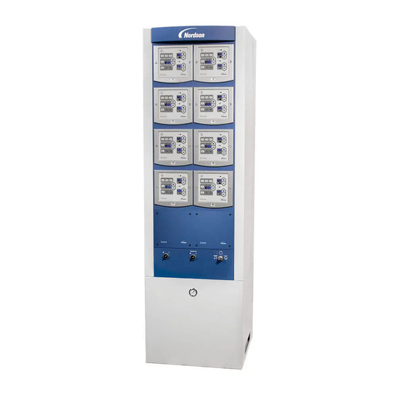
Dual Automatic Controller Multi-Gun Controller Figure 2-2 Encore LT Automatic Controllers 10. Gun controllers 12. Trigger All switch (multi-gun only) 14. Air supply pressure gauge (multi-gun only) 11. Power switch (multi-gun only) 13. -
Page 15: Triggering
Lockout: Guns cannot be triggered. If Axis Controllers are installed in the multi-gun controller, the in/out positioners and oscillators or reciprocators cannot be moved. Use this position when working inside the booth. READY LOCKOUT CONVEYOR BYPASS Figure 2-3 Interlock Keyswitch Part 1604858-01 E 2013 Nordson Corporation... -
Page 16: Specifications
The equipment must be installed and used in accordance with Standard EN50177. The Encore LT Automatic Controller can be installed in a non-hazardous area or in a hazardous area defined as a Zone 22. The Encore LT Automatic Controller with Axis Controller must be installed in a non-hazardous area. -
Page 17: Controller Dimensions And Weights
Weight = 6.2 kgs (13.6 lbs) [12.30] [1.27] [19.7] [7.79] [6.61] [21.4] 4X M5 THREAD [2.953] (TYP. TOP & BOTTOM) [1.57] [2.46] [18.8] [8.34] 6 x ∅10.0 Mounting [7.87] [2.963] Holes [1.3] Figure 2-4 Controller Dimensions (mm, [in.]) Part 1604858-01 E 2013 Nordson Corporation... -
Page 18: Controller Certification Labels
Controller Certification Labels Single Gun Controller Label ENCORE LT EN50177 FM11ATEX0057X (2) 3 D Ex tc IIIC T60°C Dc T = +15 to +40°C NORDSON CORP. AMHERST, OH, USA Vn=100−250Vac 7n=50−60Hz Pn=100VA OUTPUT: Vo = +19V Io = +1.0A (peak) (peak) WARNING −... -
Page 19: Multi-Gun (4−8 Guns) Controller Label
Description Multi-Gun (4−8 Guns) Controller Label ENCORE LT EN50177 FM11ATEX0057X (2) 3 D Ex tc IIIC T60°C Dc T = +15 to +40°C NORDSON CORP. AMHERST, OH, USA Vn=100−250Vac 7n=50−60Hz Pn=275VA OUTPUT: Vo = +19V Io = +1.0A (peak) (peak) WARNING −... - Page 20 Description Part 1604858-01 E 2013 Nordson Corporation...
-
Page 21: System Setup
Board 10mm Air Supply Manifold #1 Gun #1 Gun Cable 24 VDC 24 VDC 24VDC Power Supply Line AC Power Filter Gun #2 Gun #1 Optional External Triggers Figure 3-1 Single/Dual Gun System Diagram Part 1604858-01 E 2013 Nordson Corporation... -
Page 22: Multi-Gun System Diagram
Distribution Panel Power (Multi-Gun Controller) Supply External Trigger Board Interlock Keyswitch Trigger All Switch Line Filter AC Power Power Power Switch Distribution Distribution 16mm Manifold Figure 3-2 Encore LT Multi-Gun Automatic Controller Block Diagram Part 1604858-01 E 2013 Nordson Corporation... -
Page 23: Single/Dual Controller Mounting
Use the other 12-in. ground wire to connect the tray to the mounting plate. 11. Loosen the tray swivel bolt (6) to rotate the tray to the desired position, then tighten the bolt. Part 1604858-01 E 2013 Nordson Corporation... -
Page 24: Multi-Gun Controller Mounting
Anchor the enclosure to the floor. Provide trays or covers to prevent damage to the gun and pump air tubing and gun cables. Refer to Figure 3-4 for dimensions. Part 1604858-01 E 2013 Nordson Corporation... -
Page 25: System Connections
AUX or VBF strain reliefs and connect them to the J3 terminals on the main control board(s). The Trigger A, Conveyor Interlock, and Lockout circuits are all sinking circuits. These circuits operate on 10 mA ± 1. Part 1604858-01 E 2013 Nordson Corporation... -
Page 26: Multi-Gun Controller Connections
Make connections as shown in Figure 3-6. See Figure 3-5 for external trigger and conveyor interlock connections. Part 1604858-01 E 2013 Nordson Corporation... - Page 27 8. Auxiliary strain reliefs 11. Gun controller panels Note: Each gun controller panel provides outputs for two Encore automatic spray guns. The Axis Controller is optional. Refer to the Axis Controller manual for connections. Part 1604858-01 E 2013 Nordson Corporation...
-
Page 28: Remote Connections For Multi-Gun Controllers
LO-3 LO-4 LO-5 BLUE CON-1 BLUE CON-2 BLUE CON-3 BLUE CON-4 BLUE CON-5 BLACK BLACK BLACK BLACK BLACK REMOTE TRIGGER SIGNALS T1 = GUN #1 Figure 3-7 Multi-Gun Controller − Remote Trigger/Conveyor Interlock Connections Part 1604858-01 E 2013 Nordson Corporation... -
Page 29: System Air Supply
Bar-Mount Gun Tube-Mount Gun Figure 3-8 Gun Connections − Bar Mount and Tube-Mount Guns 1. Retainer nut 3. Barbed fitting 5. Gun cable receptacle 2. Hose connector 4. Tubing union (4-mm) Part 1604858-01 E 2013 Nordson Corporation... -
Page 30: Pump Connections
AUTO position in order for it to function properly with automatic spray guns. If it is in the MAN position the guns cannot be triggered remotely. Refer to Troubleshooting to change the jumper position. Part 1604858-01 E 2013 Nordson Corporation... -
Page 31: Entering Configuration Mode
0 = Smart, 1 = Classic Cable Length 0 = 8 meters, 1 = 12 meters, 2 = 16 meters NOTE: Refer to the Operation section for explanations of the Electrostatic Control and Powder Flow Control modes. Part 1604858-01 E 2013 Nordson Corporation... -
Page 32: Controller Triggering
3 inputs (Trigger, Conveyor Interlock, and Lockout) are pulled low (sinking). The guns can be turned off by momentarily pressing the Enable/Disable button. Refer to the External Triggering Examples on the the following page. Part 1604858-01 E 2013 Nordson Corporation... -
Page 33: External Triggering Examples
Locked Out Trigger On, Conveyor On, Actual Set Pt Set Pt Spraying No Lock Out Manual Disable Set Pt Set Pt Flashing Manual Disable Set Pt Set Pt Flashing Manual Disable Set Pt Set Pt Part 1604858-01 E 2013 Nordson Corporation... - Page 34 3-14 System Setup Part 1604858-01 E 2013 Nordson Corporation...
-
Page 35: Operation
Continuous Trigger Mode: If the gun controllers are configured for continuous triggering, use the Enable/Disable buttons to turn the guns on and off. Trigger All: For a multi-gun controller, the Trigger All switch can be used to turn all guns on or off. Part 1604858-01 E 2013 Nordson Corporation... -
Page 36: Displays And Leds
The Select Charge Modes and electrostatic setpoints are: Recoat 100 kV, 15 μA Metallics 50 kV, 50 μA Deep Recesses 100 kV, 60 μA NOTE: Pressing the + or − keys have no effect when a Select Charge mode is selected. Part 1604858-01 E 2013 Nordson Corporation... -
Page 37: Custom Electrostatic Mode
μA. Press the + or − buttons to enter the desired kV setpoint. The longer a button is pressed the faster the units change. The valid STD range is 0 or 25−100 kV. Part 1604858-01 E 2013 Nordson Corporation... -
Page 38: Classic Afc Mode
The controller varies the flow and atomizing air to a venturi-type powder pump depending on the settings. Flow air controls the amount and velocity of the powder; atomizing air dilutes the powder flow and increases the velocity. Two modes of pump air control are available: Part 1604858-01 E 2013 Nordson Corporation... -
Page 39: Smart Flow Mode Settings
At 7 bar (100 psi) supply pressure: Total Flow Flow Air Flow Air Pressure Atomizing Air Pressure Setting % Setting % bar (psi) bar (psi) 1.7 (25) 1.7 (25) 0.86 (12.5) 2.6 (37.5) In other words, Part 1604858-01 E 2013 Nordson Corporation... -
Page 40: Classic Flow Mode Settings
At 7 bar (100 psi) supply pressure: Flow Atomizing Flow Air Pressure Atomizing Air Pressure Setting % Setting % bar (psi) bar (psi) 1.7 (25) 1.7 (25) 2.7 (40) 0.689 (10) Part 1604858-01 E 2013 Nordson Corporation... -
Page 41: Daily Operation
Monitor the μA output daily, under the same conditions. A significant increase in μA output indicates a probable short in the gun resistor. A significant decrease indicates that a resistor or electrostatic power supply requires service. Part 1604858-01 E 2013 Nordson Corporation... -
Page 42: Interface Messages
Vacuum dust and powder from equipment. Recommended Cleaning Procedure for Powder Contact Parts Nordson Corporation recommends using an ultrasonic cleaning machine and Oakiter BetaSolv emulsion cleaner to clean gun and pump powder contact parts. - Page 43 4. Rinse all parts in clean water and dry before re-assembly. Inspect the O-rings and replace any that are damaged. NOTE: Do not use sharp or hard tools that will scratch or gouge the smooth surfaces of powder contact parts. Scratches will cause impact fusion. Part 1604858-01 E 2013 Nordson Corporation...
- Page 44 4-10 Operation Part 1604858-01 E 2013 Nordson Corporation...
-
Page 45: Troubleshooting
Failure to observe this warning could result in personal injury. These troubleshooting procedures cover only the most common problems. If you cannot solve a problem with the information given here, contact your local Nordson representative for help. Controller Faults Problem Possible Cause Corrective Action 15. -
Page 46: General Troubleshooting Chart
Worn nozzle or deflector Remove and inspect the nozzle or pattern deflector. Replace worn parts. Plugged electrode assembly or Remove and clean the electrode powder path assembly. If necessary, remove the and clean the powder path. Continued... Part 1604858-01 E 2013 Nordson Corporation... - Page 47 0 kV, If an open or short is found, replace 0 mA the cable. Spray gun power supply shorted Perform the Power Supply Resistance Test as described in the gun manual. Continued... Part 1604858-01 E 2013 Nordson Corporation...
- Page 48 The cable should be inserted past the white line marked towards the end of the cable. Push the black bar back into the white connector to secure. Part 1604858-01 E 2013 Nordson Corporation...
-
Page 49: Parts
Parts Section 6 Parts Introduction To order parts, call the Nordson Industrial Coating Systems Customer Support Center at (800) 433-9319 or contact your local Nordson representative. This section covers parts for the dual and multi-gun controllers, powder and air tubing, and options. Refer to the following manuals for additional information and optional equipment. -
Page 50: Single Controller Parts
Parts Single Controller Parts See Figures 6-1 and 6-2 and the parts list on the following page. Figure 6-1 Single Controller Parts (1 of 2) Part 1604858-01 E 2013 Nordson Corporation... -
Page 51: Single Controller Parts List
WASHER, flat, 0.203 x 0.406 x 0.040, brass 983469 LUG, 90, double, 0.250, 0.438 240674 TAG, ground 1045837 SCREW, pan head, recessed, M5 x 12, w/lockwasher −−−−−− PANEL, sub-assembly, 1 gun, Encore automatic NOTE A: See Figure 6-2 for service parts. Part 1604858-01 E 2013 Nordson Corporation... -
Page 52: Single Controller Rear Panel Parts
Parts Single Controller Rear Panel Parts This panel is used only on the single gun controller. Figure 6-2 Single Controller Rear Panel Parts (2 of 2) Part 1604858-01 E 2013 Nordson Corporation... -
Page 53: Single Controller Rear Panel Sub-Assembly Parts List
S GASKET, manifold, controller, Encore LT 1099281 S VALVE, solenoid, 3 port, 24V, 0.35W 1107582 S REGULATOR, electro-pneumatic, w/harness, Encore automatic 1107696 S FILTER, line, RFI power, 3A, w/0.250 terminals NOTE A: See Figure 6-4 for service parts. Part 1604858-01 E 2013 Nordson Corporation... -
Page 54: Dual Controller Parts
Parts Dual Controller Parts See Figure 6-3 and the parts list on the following page. Figure 6-3 Dual Controller Parts Part 1604858-01 E 2013 Nordson Corporation... -
Page 55: Dual Controller Parts
NUT, lock, 1/2 in. NPT, nylon 1107537 CORD, power, 15 ft (4.6 m), w/0.250 terminals −−−−−− PANEL, sub-assembly, 2 gun, controller, Encore automatic NOTE A: See Figure 6-4 for service parts. AR: As Required Part 1604858-01 E 2013 Nordson Corporation... -
Page 56: Dual And Multi-Gun Rear Panel Sub-Assembly
Parts Dual and Multi-Gun Rear Panel Sub-Assembly This panel is used on both the dual controller and the multi-gun controller. Figure 6-4 Rear Panel Sub-Assembly Parts − Dual and Multi-Gun Controllers Part 1604858-01 E 2013 Nordson Corporation... -
Page 57: Dual And Multi-Gun Rear Panel Sub-Assembly Parts List
REGULATOR, electro-pneumatic NOTE A: If replacing this connector, check the original connector ID. The 1604492 connector has a 0.4 mm orifice. The 1062009 connector does not. Order the correct connector for your version of controller. Part 1604858-01 E 2013 Nordson Corporation... -
Page 58: Multi-Gun Controller Parts
6-10 Parts Multi-Gun Controller Parts Front Panel Parts Figure 6-5 Multi-Gun Controller Front Panel Parts Part 1604858-01 E 2013 Nordson Corporation... -
Page 59: Multi-Gun Controller Front Panel Parts List
NUT, hex, M5, brass 983401 WASHER, lock, split, M5, steel, zinc 983021 WASHER, flat, 0.203 x 0.406 x 0.040, brass 240674 TAG, ground 334806 SWITCH, round, 2 position, 90 degree 1000594 SWITCH, keylock, 3 position Part 1604858-01 E 2013 Nordson Corporation... -
Page 60: Multi-Gun Controller Rear Panel Parts
Multi-Gun Controller Rear Panel Parts See Figure 6-4 for the dual and multi-gun rear panel sub-assembly and parts list. Each panel provides the outputs for 2 automatic spray guns. Figure 6-6 Multi-Gun Controller Rear Panel Parts Part 1604858-01 E 2013 Nordson Corporation... -
Page 61: Multi-Gun Controller Rear Panel Parts List
973076 NIPPLE, steel, schedule 40, 1/2 in. NPT, 1.12 in. 240976 CLAMP, ground, w/wire NOTE A: Refer to Rear Panel Sub-Assembly on page 6-9 for a parts breakdown. AR: As Required NS: Not Shown Part 1604858-01 E 2013 Nordson Corporation... -
Page 62: System Parts And Options
NOTE A: Use for mounting a one or two dual controllers on a wall. E: Optional filter kit for use with single and dual gun controllers. Kit includes fittings and mounting bracket. F: 4 and 6 gun controllers only. G: Multi-gun controller only. Part 1604858-01 E 2013 Nordson Corporation... -
Page 63: Wiring Diagrams
Wiring Diagrams Section 7 Wiring Diagrams Part 1604858-01 E 2013 Nordson Corporation... - Page 64 Wiring Diagrams Part 1604858-01 E 2013 Nordson Corporation...
- Page 65 Encore LT Automatic Controller Wiring Diagrams ENCORE LT CONTROL PCA ENCORE AUTO CONTROLLER MANIFOLD ASSY ENCORE LT/AUTO KEYPAD PANEL J7 (VBF) DETAIL A 1500mm CONNECTOR WIRES 1065542 (RED) NOZZLE (BLACK) NOZZLE NOZZLE (RED) FLOW (BLACK) FLOW FLOW (WHITE) FLOW (RED) ATOMIZING...
- Page 66 Encore LT Automatic Controller Wiring Diagrams ENCORE LT CONTROL PCA ENCORE AUTO CONTROLLER MANIFOLD ASSY ENCORE LT/AUTO KEYPAD PANEL J7 (VBF) DETAIL A 1500mm CONNECTOR WIRES 1065542 (RED) NOZZLE (BLACK) NOZZLE NOZZLE (RED) FLOW (BLACK) FLOW FLOW (WHITE) FLOW (RED) ATOMIZING...
- Page 67 Encore LT Automatic Controller Wiring Diagrams CONVEYOR TRIGGER ALL POWER ON/OFF KEYLOCK SWITCH 2 POSITION SWITCH 2 POSITION SWITCH 1000594 334806 334806 CONTACT BLOCK CONTACT BLOCK CONTACT BLOCK 1000595 288806 288806 TRIGGER DISTRIBUTION HARNESS TO GUN MODULES (SEE SHEETS 2-9) SWITCH TO T.B.
- Page 68 Encore LT Automatic Controller Wiring Diagrams ENCORE LT CONTROL PCA ENCORE AUTO ENCORE LT/AUTO KEYPAD PANEL CONTROLLER MANIFOLD ASSY J7 (VBF) DETAIL A 1500mm CONNECTOR WIRES (RED) NOZZLE (BLACK) NOZZLE NOZZLE (RED) FLOW (BLACK) FLOW FLOW (WHITE) FLOW (RED) ATOMIZING...
- Page 69 Encore LT Automatic Controller Wiring Diagrams ENCORE LT CONTROL PCA ENCORE AUTO ENCORE LT/AUTO KEYPAD PANEL CONTROLLER MANIFOLD ASSY J7 (VBF) DETAIL A 1500mm CONNECTOR WIRES (RED) NOZZLE (BLACK) NOZZLE NOZZLE (RED) FLOW (BLACK) FLOW FLOW (WHITE) FLOW (RED) ATOMIZING...
-
Page 70: Declaration Of Conformity
DECLARATION of CONFORMITY PRODUCT: Encore LT Automatic and Manual Powder Spray Systems Models: Encore Automatic Applicator and Encore LT Automatic Controllers Encore LT Manual Applicator with Encore LT Manual Controller Description: The automatic electrostatic powder spray system includes applicator, control cable, and associated controllers. - Page 71 MATERIAL NO. REVISION 1107700 NOTICE THIS DRAWING IS NORDSON PROPERTY,CONTAINS PROPRIETARY INFORMATION AND MUST BE RETURNED UPON REQUEST. DO NOT CIRCULATE, REPRODUCE OR DIVULGE TO OTHER PARTIES WITHOUT WRITTEN CONSENT OF NORDSON. ENCORE AUTO CONTROLLER ENCORE AUTO CONTROLLER SINGLE GUN 2-GUN THE FOLLOWING CONTROLLERS ARE SUITABLE FOR CLASS II, DIV 2, GROUP F &...
Need help?
Do you have a question about the Encore LT Automatic and is the answer not in the manual?
Questions and answers