Table of Contents
Advertisement
Quick Links
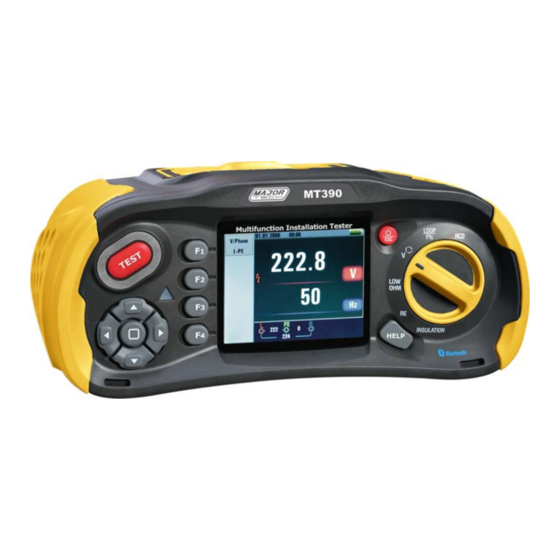
M 390
T
t
Multifunction Tester
User Manual
6 Functions
Insulation Resistance
LOW OHW
Voltage
Loop Impedance
RCD
2014
Advertisement
Table of Contents

Related Manuals for Major tech MT390


Summary of Contents for Major tech MT390
- Page 1 M 390 Multifunction Tester User Manual 6 Functions Insulation Resistance Earth Resistance LOW OHW Voltage Loop Impedance 2014...
- Page 2 Multifunction Tester User Manual...
- Page 3 Multifunction Tester User Manual Page Contents 1-Safety Considerations ................. 1.1-International Symbols ..............1.2-Terminology ................. 1.3-Warnings ..................1.4-Caution ..................1.5-Declaration of Conformity ............... 1.6-Error Codes .................. 2-Specification ..................3-General Specification ................4-Instrument Overview ................4.1-Front View ..................4.2-Connector Panel ................4.3-Battery & Fuse ................4.4-Understanding the Display ...............
- Page 4 Multifunction Tester User Manual Warning! You must read and completely understand the Safety Considerations part of this manual before using the instrument. 1-Safety Considerations This manual contains instructions regarding the safe use and the proper functioning of the instrument. If not complied with, the user could be exposed to danger and the instrument to possible damage.
- Page 5 Multifunction Tester User Manual 1.4-Caution Do not change functions on the test instrument with the test leads in place, i.e. changing from a “dead test” to a test where the supply is required could damage the instrument. 1.5-Declaration of Conformity This instrument has been tested according to the below regulations: EN 61326: Electrical equipment for measurement, control and laboratory use.
- Page 6 Multifunction Tester User Manual Notes [1] Valid for resistance of neutral circuit <20Ω and up to a system phase angle of 30°. Test leads must be zeroed before testing. [2] Valid for mains voltage >200V. L- PE (No Trip) Range(Ω) Resolution(Ω) Accuracy 0.23 9.99...
- Page 7 Multifunction Tester User Manual Accuracy of the Current of the RCD: ± (5% of reading + 1digits) Resolution of the RCD Timing: 0.1ms Voltage and Frequency Measurement Range Resolution(V) Accuracy (V)/AC-DC ±(2% of reading +2digits) 80 500 Measurement Range Resolution(Hz) Accuracy (Hz) 45 65...
- Page 8 Multifunction Tester User Manual 3-General Specification 8 x 1.5V AA Size Alkaline batteries Power Source or 8 x 1.2V AA Size rechargeable Ni-MH batteries Average of 15hours Battery Life IV 400V CAT Rating Double Insulation Protection Classification Protection Rating LCD Screen Type 3.5”TFT 320x240 Pixels...
- Page 9 Multifunction Tester User Manual 4.2-Connector Panel Input Terminal to operate the switched probe L - Line Input PE - Protective Earth Input N - Neutral Input Input Terminal to operate the switched probe Ω Ω CAT III 600V TV OUT RESET TV OUT System Reset...
- Page 10 Multifunction Tester User Manual 4.4-Understanding the Display 25 24 23 22 21 Annunctator Function Value AUTO RCD TIME X1/2 RCD TIME RAMP RCD TRIP Loop/PFC L-PE V/Phase L-PE Continuity 0.5Ω 1.0Ω 2.0Ω 5.0Ω...
- Page 11 Multifunction Tester User Manual Annunctator Function 10.0Ω Continuity 20.0Ω 50.0Ω 50.0Ω Terminal Voltage 1000 30mA Trip Current 100mA 300mA 500mA 650mA 1000mA 10mA Current NO Trip Hi Amp Beeper Type of RCD Lock 0° 0°/180° 180° ZERO 0.125MΩ Reference 0.25MΩ 0.5MΩ...
- Page 12 Multifunction Tester User Manual Meaning Annunctator Low battery icon. See :Indicates the battery status. :100% :80% :50% :20% :Low Battery for additional information on batteries and power management. Beeper Lock Hold Datalog Bluetooth Appears when the instrument is overheated. Display 30 seconds (time-delayed) Being tested Primary display and measurement units.
- Page 13 Multifunction Tester User Manual 5-How to Use the Tester 5.1-Important Symbols and Messages during the measurement Figure 1 Screen Description Battery status Displayed measured value The measurement unit of the measured value The indication of the correct input terminal connection Displayed menu 5.1.1-Displayed icons (symbols) and messages in VOLTAGE function :Indicates the correct input terminal connectivity .
- Page 14 Multifunction Tester User Manual 5.1.2-Displayed icons (symbols) and messages in LOOP/PFC function :Indicates the correct input terminal connectivity . The user should connect the test leads to the appropriate terminals. :Indicates L connection is connected on the N input terminal and vice-versa :Indicates no connection on the PE input terminal If the wiring condition is other than normal, the Tester is limited on its measurements that can be performed.
- Page 15 Multifunction Tester User Manual : Low Battery : Indicates high temperature and therefore cannot make any measurements Message: Half: Appears during the auto test when rcd has operated on the x ½ test Half Trip: Appears during the manual test when rcd has operated on the x ½ test UL OVER: Appears when UF voltage exceeds the previously set UL voltage.
- Page 16 Multifunction Tester User Manual 5.2.1-Using the No Trip LOOP Measurement to be selected where the circuit is protected by an RCD whose rating is 30mA or above Turn the rotary switch to the LOOP/PFC position Connect the test leads as Figure Figure If voltage of the L- PE on the lower left appears, the unit is ready to TEST Press the TEST button when ready...
- Page 17 Multifunction Tester User Manual 5.2.2-LOOP / PFC Function Menu Operation Main Display Menu Display F1 Button: Pop-up and shutdown Loop/PFC menu , Shutdown mode is activated when the user selects. F2 Button: Pop-up and shutdown Current menu , Shutdown mode is activated when the user selects F3 Button: None F4 Button:...
- Page 18 Multifunction Tester User Manual When measuring is completed, impedance of L- PE PFC (lf) value appears on the screen Press TEST button if re-test is necessary. When symbol from appears lower left corner, and if the voltage exceeds 260V, the measurement will not take place 5.2.3-Using the Hi Amp LOOP Measurement to be selected where the circuit is NOT protected...
- Page 19 Multifunction Tester User Manual When the measuring is complete the impedance of L-PE and PFC (lf) value appears on the screen Press TEST button if re-test is necessary 0.41 When symbol from Current appears lower left corner, and if the voltage Hi Amp exceeds 260V, the measurement will not take place...
- Page 20 Multifunction Tester User Manual When measuring is completed, impedance of L - N and PSC value appears on the screen Press TEST button if re-test is necessary When symbol from appears lower left corner, and if the voltage exceeds 260V, the measurement will not take place 5.2.5-Using The RCD Function You can select UL Voltage by Pressing and hold...
- Page 21 Multifunction Tester User Manual Function Button Description BUTTON AUTO RCD tΔ RCD IΔN 30mA 100mA 300mA 500mA 650mA 10mA AC G AC S DC G DC S G: General (non-delayed) RCDs S: Selective (time-delayed) RCDs Possible setup ratios depending on the RCD Trip Current 10mA 30mA 100mA...
- Page 22 Multifunction Tester User Manual Using the Functions activated by F1 button Using the AUTO Mode Turn the rotary switch to the RCD position Initial screen is setup to the AUTO Using the F2 and F3 button, select the rating and the type of the RCD Connect test leads as shown in the Figure 15...
- Page 23 Multifunction Tester User Manual Using the x1/2, x1 and x5 manual selection 01.01.2013 00:32 Turn the rotary switch to the RCD position Press F1 and aspect button from the AUTO to 19.5 select x1/2, x1 and x5 Trip 3 Using the F2 and F3 button, select the RCD’s trip 30mA current and type of the RCD.
- Page 24 Multifunction Tester User Manual 5.2.6-RCD Function Menu Operation Main Display RCD AUTO Other 00:45 Menu Display F1 Button: Pop-up and shutdown RCD menu , Shutdown mode is activated when the user selects. Pop-up and shutdown Trip Current menu , Shutdown mode is activated when the user selects F2 Button: F3 Button: Pop-up and shutdown Type of RCD menu , Shutdown mode is activated when the user selects...
- Page 25 Multifunction Tester User Manual 5.2.7-Using the VOLTAGE Function WARNING! Do not use on a circuit whose voltage either L-L or L-N exceeds 550V Measuring the Voltage and Frequency Figuire 19 Standby screen for the Voltage and Frequency Connect the test lead input terminal Turn the rotary switch to the VOLTAGE position Do not attempt to measure when the input voltage is above 500V a.c.
- Page 26 Multifunction Tester User Manual H LP Figure 22 Phase Sequence-Test lead connection When the line conductors are connected in the correct sequence 1.2.3 and the symbol will appear as Figure 23 However, connected in the wrong sequence, 2.1.3 and the circle symbol will change to the symbol displayed below Figure 23 Phase Sequence screen-when connected in clockwise direction.
- Page 27 Multifunction Tester User Manual 5.2.9-Voltage/Phase Function Menu Operation Main Display Menu Display F1 Button: Pop-up and shutdown Voltage/Phase menu , Shutdown mode is activated when the user selects. F2 Button: None F3 Button: None F4 Button: None Up Button: Up menu to select the current active sub-options. Down Button: Down menu to select the current active sub-options.
- Page 28 Multifunction Tester User Manual Menu Display Termi... Termi... Termi... 125V 125V 125V Beeper Beeper Beeper Lock Lock Lock Reference Reference Reference 0.125M 0.125M 0.125M F1 Button: Pop-up and shutdown Insulation menu , Shutdown mode is activated when the user selects. F2 Button: Pop-up and shutdown Insulation menu , Shutdown mode is activated when the user selects.
- Page 29 Multifunction Tester User Manual 6.4-Earth Resistance Display/Switch and Terminal Settings The earth resistance test is a 3-wire test consisting of two test stakes and the earth electrode under test. This test requires an accessory stake kit. Connect as shown in right figure . Best accuracy is achieved with the middle stake at 62 % of the distance to the far stake.
- Page 30 Multifunction Tester User Manual A continuity test is used to verify the integrity of connections by making a high resolution resistance measurement. This is especially important for checking Protective Earth connections. 6.8-LOW OHM Function Menu Operation Main Display Menu Display F1 Button: Pop-up and shutdown LOW OHM menu , Shutdown mode is activated when the user selects.
- Page 31 Multifunction Tester User Manual 7-Menu Items Menu System Settings Data Record Run Settings Press the button to select the System Settings, Data Record or Run Settings. Then press the button to enter. 8-System Settings Items Menu Languages Date/Time Memory Auto screen-off Auto power-off System default settings System upgrade...
- Page 32 Multifunction Tester User Manual 8.2-Date/Time Press the button to select the date or time, Then press the button to enter, Press the button to adjust the value, Press the button to select the Items ,press the ESC button to esc and save. 8.3-TV Press the button to select the output...
- Page 33 Multifunction Tester User Manual 8.5-Auto Screen-off Default 3 Minutes, Press the button to select the Auto screen-off time, press ESC button to esc and save the select the time. 8.6-Auto Power-off Default 10 Minutes, Press the button to select the Auto power-off time, press ESC button to esc and save the select the time.
- Page 34 Multifunction Tester User Manual 8.8-System Upgrade Then press the button to enter. 9-Run Settings Items Menu On or off the Bluetooth Data Record Datalog Press the button to select the Items, then press the button to enter. 9.1-Bluetooth Off the Bluetooth On the Bluetooth Press the button to select the on or off bluetooth , press the ESC button to esc and save.
- Page 35 Multifunction Tester User Manual 9.2-Data Record Menu Items F1 button Backspa F2 button Enter Data Record Enter characters Press the button to select the characters , press the button to Enter characters. NOTE: Data recording shortcuts, press the left button. 9.3-Datalog Menu Items...
- Page 36 Multifunction Tester User Manual 10.1-Delete Files Press Help/Delete button to menu, Press the button to select the Yes or No , press button to execute. 10.2-Data Record Preview Main Display F1 Button: None F2 Button: None F3 Button: None F4 Button: None Up Button: Turned up view log data...
- Page 37 Multifunction Tester User Manual 10.3-Menu 10.3.1-Data record 10.3.2-Datalog Settings Menu Display F1 Button: None F2 Button: None F3 Button: None F4 Button: None Up Button: Select up Down Button: Select down Left Button: None Right Button: None Enter Button: Confirm the user select mode Press the button to select the Items, Then press the button to enter...
- Page 38 Multifunction Tester User Manual Drawing 10.4- 7 8 9 10 11 Annunctator Meaning File Name File named: Month/day File type LOOP PFC LOG 01-01 00-03-13.txt Function Hours/minutes/seconds Primary display and measurement units. Primary display and measurement units. Coordinate Function Function hours/minutes/seconds Record time L-FE Value...
- Page 39 Multifunction Tester User Manual 10.5-Datalog Color WARNING! • Measurements should only be performed on de-energized circuits. • Measurements may be adversely affected by impedances or parallel circuits or transient currents. To Measure Continuity Turn the rotary switch to the RLO position. Use the L and N (red and black) terminals for this test.
- Page 40 Rev. 140123 2014...
Need help?
Do you have a question about the MT390 and is the answer not in the manual?
Questions and answers