Table of Contents
Advertisement
Quick Links
Advertisement
Table of Contents

Related Manuals for Major tech MT560


Summary of Contents for Major tech MT560
- Page 1 INSTRUCTION MANUAL MT560 DIGITAL INSULATION TESTER...
-
Page 3: Table Of Contents
Contents Page no 1. Safety Information................4 2. Safety Symbols..................4 3. Specifications..................4 3.1. General Information..............4 3.2. Electrical Specifications............5 4. Parts & Control..................7 4.1. How to connect test leads............7 4.2. Battery Check-UP & Replacement..........7 4.3. Test leads check...............7 4.4. Rotary Switch positions.............7 4.5. -
Page 4: Safety Information
1. SAFETY INFORMATION • Read the following safety information carefully before attempting to operate or service the meter. • To avoid damages to the instrument do not apply the signals which exceed the maximum limits shown in the technical specifications tables. •... -
Page 5: Electrical Specifications
Range Function Display Large LCD with dual display Measurement Range 4000MΩ/125V, 4000MΩ/250V, 4000MΩ/500V, 4000MΩ/1000V, 400Ω/BZ, to 500V, decreasing linearly to ≤1.5 at 1000V, 1000V/DCV, 750V/ACV Sampling Rate 2.5 times per second. Zero Adjustment Automatic adjustment. Over Range Indicator "OL" of highest digit is displayed. Low Battery Indication The is displayed when the battery Voltage drops below the operating voltage. - Page 6 DC Voltage Range Resolution Accuracy Input Overload Impedance Protection 1000V 10MΩ 1000Vrms ±(0.8%+3) AC Voltage (40Hz~400Hz) Range Resolution Accuracy Input Overload Impedance Protection 750V ±(1.2%+10) 10MΩ 750Vrms Meg OHMS Terminal Range Resolution Accuracy Test Short Voltage Current Circuit Current 125V 0.125~4.000MΩ...
-
Page 7: Parts & Control
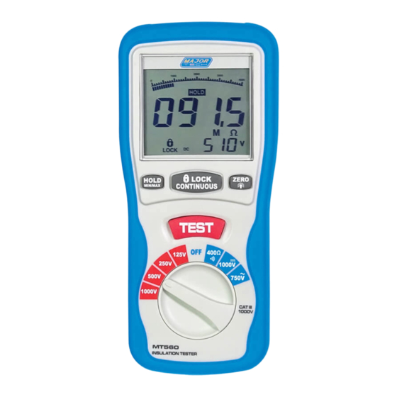
4. PARTS & CONTROLS 1. Digital Display 2. Data Hold Button; MAX/MIN 3. Lock Button 4. Backlight Button; ZERO 5. Test Button 6. Rotary Function switch 7. VΩ Jack 8. COM input jack 9. Pothook 10. Battery Cover 4.1. How to connect test leads. On MΩ... -
Page 8: Insulation Resistance Measurements
TEST: In the insulation resistance testing function, pressing and holding the "TEST" button, the meter will inject high-voltage, and enter into the insulation resistance testing, release the "TEST" button and it will cut off the high-voltage and exit form the insulation resistance testing. ZERO/LIGHT: Press the “ZERO/LIGHT”... -
Page 9: Low Resistance (Continuity)Measurements
or its voltage is lower than 30V, it will enter into the formal testing process and inject the high-voltage on the primary display, the insulation resistance in MΩ is indicated in-phase with analog bar; on the secondary display, the tested insulation voltage in V (DC) is indicated, the symbol "... - Page 10 connected to the housing would be connected to some metal part lf the tool (e.g. chuck, blade). Note: The switch of the device must be in the "ON" position and the main power should be disconnected. MOTORS AC-Disconnect the motor from the line by disconnecting the wires at the motor terminals or by opening the main switch.
- Page 11 CABLES Disconnect the cable from the line. Also disconnect opposite end to avoid errors due to leakage from other equipment. Check each conductor to ground and /or lead sheath by connecting one megohmmeter lead to a ground and /or lead sheather and the other megohmmeter lead to each of the conductors in turn.
- Page 12 MAJOR TECH (PTY) LTD South Africa Australia www.major-tech.com www.majortech.com.au sales@major-tech.com info@majortech.com.au...
Need help?
Do you have a question about the MT560 and is the answer not in the manual?
Questions and answers