Table of Contents
Advertisement
Quick Links
This product is covered by one or more of the following patents.
European Patent 851,211 B1; 1,111,690 B1; 1,148,346 B1; 1,209,487 B1.
Italian Patent IT 1,321,772.
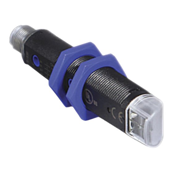
S5N-Px SERIES
INSTRUCTION MANUAL
Information on IO-Link communication is available on the last
page of this manual.
CONTROLS
OUTPUT LED (S5N-Px...B01/C01/T01)
The yellow LED ON indicates that the NO output status is closed.
STABILITY LED (S5N-Px...B01/C01)
The green LED ON indicates that the received signal has a reserve
greater than 30% compared to the output switching value.
TRIMMER (S5N-Px...B01/C01/T01)
The trimmer can be used to adjust sensitivity; the operating distance
increases turning the trimmer clockwise.
WARNING: The trimmer rotation is limited to 270° by a mechanical stop.
Do not apply excessive torque when adjusting (max 40 Nmm).
INSTALLATION
The sensor can be fixed by means of the M18x1 threaded body through
a 18mm hole, using the specific washer and the two CH.24 nuts
enclosed (1.5Nm maximum tightening torque).
Alternatively, the sensor can be mounted through the two housing's
holes using two screws (M3x22 or longer) and washer.
Amongst the various possible solutions, we suggest to choose the
combination that offers the best visibility of the signalling LEDs and the
easiest access to the trimmer.
Wide range of accessories available: 22mm nuts, h=8mm, (2Nm
maximum tightening torque) guarantee an improved torque and various
orientable fixing brackets ease the sensor
positioning (please refer to the accessories
listed in the general catalogue).
The operating distance is measured from the
front surface of the sensor lens.
C models: To improve the detection, the
object has to be moved closer or further away
from the front surface of the sensor lens.
In case of lateral translation, the object must
move as indicated in the figure.
CONNECTIONS
The connections are compliant to the EN 60947-5-2 standard.
M12 CONNECTOR
N.C. OUTPUT
+
10 ... 30 Vdc
2
1
3
4
N.O. OUTPUT/
0 V
-
IO-Link
AXIAL VERSION
L
14.5
2
1.5
3.5
4
4
25
X
2.5
10
TRIMMER
M O D E L S
with trimmer
L
67
N°.2 Ø3.8
X
43
STABILITY LED
X1
34
X1
OUTPUT LED
15
FIBRE OPTIC VERSION
72.5
12
1.5
4
4
25
TRIMMER
N°.2 Ø3.8
OUTPUT LED
39.5
15
TECHNICAL DATA
S5N-PA AXIAL VERSION
Power supply:
Ripple:
Current consumption
(output current excluded):
Outputs:
Output current:
Output saturation voltage:
Response time:
Switching frequency:
Indicators:
Setting:
Operating temperature:
Storage temperature:
Insulating strength:
Insulating resistance:
Operating distance (typical values):
B01: 0.1...3.5 m on R2
T01: 0.1...1 m on R2
Emission type:
Ambient light rejection:
0.5 mm amplitude, 10 ... 55 Hz frequency, for every axis (EN60068-2-6)
Vibrations:
Shock resistance:
Housing material:
Lens material:
Mechanical protection:
Connections:
Weight:
AtEx 2014/34/EU:
I I 3G EX nA II T6
I I 3D EX tD A22 IP67 T85°C
DIMENSIONS
RADIAL VERSION
L
14.5
12
2
1.5
3.5
4
4
25
X
14.5
10
TRIMMER
without trimmer
57
42
N°.2 Ø3.8
STABILITY LED
24
X1
15
OUTPUT LED
14.5
CABLE VERSION
6.2
=
10
OUTPUT LED
STABILITY LED
S5N-PR RADIAL VERSION
10 ... 30 Vdc (limit values)
2 Vpp max.
35 mA max.
NO and NC; PNP or NPN (short-circuit protection)
100 mA max.
2 V max.
0.5 ms (2 ms mod.F01/G00)
1KHz (250 Hz mod.F01/G00)
OUTPUT LED (YELLOW) excluding mod.G00
STABILITY LED (GREEN) (mod.B01/C01/C21/E01/F01)
POWER ON LED (GREEN) (mod.G00)
sensitivity trimmer (mod.B01/C01/C21/E01/F01/T01)
-25 ... 55 °C
-25 ... 70 °C
500 Vac 1 min., between electronics and housing
>20 M 500 Vdc, between electronics and housing
B01: 0.1...2 m on R2
C01: 0...60 cm
C01: 0...35 cm
T01: 0.1...1 m on R2
red (630 nm) (mod. E01) / red (660 nm) (mod.B01/T01) /
infrared (880nm) (mod. C01/C21/G00)
according to EN 60947-5-2
11 ms (30 G) 6 shock for every axis (EN60068-2-27)
PBT
PMMA
IP67
M12 - 4 pole connector
25 g. max. connector vers.
SETTING
Setting of S5N-Px...B01/T01
Position the sensor and reflector on opposite sides.
Turn the sensitivity trimmer to the maximum position.
Moving the sensor both vertically and horizontally, determine the power on and off
points of the yellow LED (OUT) and then mount the sensor in the middle of the
points defined. Optimum operation is obtained when the green LED (mod.B01) is
ON and the yellow LED is OFF.
B01 models: If necessary reduce sensitivity in order to detect very
small targets. In order to improve alignment, repeat the procedure
detailed above whilst progressively reducing the sensitivity.
T01 model: Turn the sensitivity trimmer counterclockwise until the
yellow LED turns ON (pos.A). Turn slowly the trimmer again clockwise until the
yellow LED turns OFF (Operating condition, pos.B).
M O D E L S
Setting of S5N-Px...C01
with trimmer
without trimmer
L
79
69
Turn the sensitivity trimmer to minimum: the green LED is ON, the yellow LED is
X
43
42
OFF. Position the target to detect in front of the sensor or of the fibre terminals.
X1
46
36
Turn the sensitivity trimmer clockwise until the yellow LED turns ON (Target
detected state, pos.A).
mm
Remove the target, the yellow LED turns OFF.
Turn the sensitivity trimmer clockwise until the yellow LED turns ON (Background
detected state, pos.B).
The trimmer reaches maximum if the background is not detected.
10
Turn the trimmer to the intermediate position C, between the two positions A and
B. The green LED must be ON.
STABILITY LED
Datalogic S.r.l.
Via S. Vitalino 13 - 40012 Calderara di Reno - Italy
Tel: +39 051 3147011 - Fax: +39 051 3147205 - www.datalogic.com
Helpful links at www.datalogic.com: Contact Us, Terms and Conditions,
Support.
The warranty period for this product is 36 months. See General Terms and
Conditions of Sales for further details.
For information about the disposal of Waste Electrical
and Electronic Equipment (WEEE), please refer to the
website at www.datalogic.com.
© 2007 - 2019 Datalogic S.p.A. and/or its affiliates ALL RIGHTS
RESERVED Without limiting the rights under copyright, no part of this
documentation may be reproduced, stored in or introduced into a retrieval
system, or transmitted in any form or by any means, or for any purpose,
without the express written permission of Datalogic S.p.A. and/or its
affiliates. Datalogic and the Datalogic logo are registered trademarks of
Datalogic S.p.A. in many countries, including the U.S.A. and the E.U. All
other trademarks and brands are property of their respective owners.
Datalogic reserves the right to make modifications and improvements
without prior notification.
821006321 Rev. B
A
C
B
MIN
MAX
Advertisement
Table of Contents

Related Manuals for Datalogic IO-Link S5N-P Series


Summary of Contents for Datalogic IO-Link S5N-P Series
- Page 1 Vibrations: N.C. OUTPUT 10 … 30 Vdc © 2007 - 2019 Datalogic S.p.A. and/or its affiliates ALL RIGHTS Shock resistance: 11 ms (30 G) 6 shock for every axis (EN60068-2-27) RESERVED Without limiting the rights under copyright, no part of this...
-
Page 2: Manuale Istruzioni
(630 nm) (mod. E01) / rossa (660 nm) (mod.B01/T01) / CONNETTORE M12 infrarossa (880nm) (mod. C01/C21/G00) © 2007 - 2019 Datalogic S.p.A. e/o le sue consociate TUTTI I DIRITTII RISERVATI. Senza con ciò limitare i diritti coperti dal Reiezione alla luce ambiente: come prescritto da EN 60947-5-2 ampiezza 0.5 mm, frequenza 10 …... -
Page 3: Installation
Via S. Vitalino 13 - 40012 Calderara di Reno - Italy Schaltfrequenz: 1 KHz (250 Hz bei Mod. F01/G00) sich ab Optikfläche. Tel: +39 051 3147011 - Fax: +39 051 3147205 - www.datalogic.com OUTPUT LED (gelb) ausgenommen Mod. G00 C Modelle: Die Erfassung eines Objektes Anzeigen: STABILITÄT LED (grün) bei Mod. -
Page 4: Manuel D'instructions
EN 60947-5-2 0.5 mm amplitude, 10 … 55Hz fréquence, pour chaque axes (EN60068-2-6) CONNECTEUR M12 © 2007 – 2019 Datalogic S.p.A. et/ou ses filiales TOUS DROITS RÉSERVÉS. Vibrations: Aucune partie de cette documentation ne peut être reproduite, stockée ou Résistance aux chocs:... -
Page 5: Physical Layer
parameters PHYSICAL LAYER FEATURES Description Description Block Parameter IO-Link Revision Data Storage SIO Modus Min Cycle Time 5 ms (LED models) / 8 ms (Laser models) Parameter (write) access Supported Access Locks Data Storage Transmission Rate 38,4 kbit/s (COM2) PDInput: 24 Bit Process Data Length Device Profile: Smart Sensor PDOutput: 1 Bit... - Page 6 Lenght Value/Range Description Data Type Access* Remark (dec) Object Name (offset) 0x0010 (16) Vendor Name 9 octets DATALOGIC Informative StringT 0x0011 (17) Vendor Text 19 octets Empower your vision StringT 0x0012 (18) Product Name 15 octets Detailed product name StringT See “Device variant collection”...
- Page 7 Teach-in Parameters Index Parameter Subindex Lenght Value/Range Description Data Type Access* Remark (dec) Object Name (offset) 0x00 = SSC1 (default, C/Q pin and DO C/Q and DO outputs are antivalent. 0x003A (58) TI Select 1 octet Selection for Teach-in channel (volatile) UIntegerT pin) Teach SSC1 equals to teach SSC2...
-
Page 8: Process Data
Standard Command Index (dec) Command Name Lenght Value (dec) Description Access* Acquisition EASY (refer to User’s Manual) (M03, W03) / Teach Set Point (B01, C01, T01) 0x0002 (2) SP1 Single Value Teach 1 octet 0x41 (65) 0x0002 (2) SP1 Teach TP1 1 octet 0x43 (67) Acquisition FINE: Mark Detection (refer to User’s Manual) (W03) - Page 9 CE Compliance CE marking states the compliance of the product with essential requirements listed in the applicable European directive. Since the directives and applicable standards are subject to continuous updates, and since the manufacturer promptly adopts these updates, therefore the EU declaration of conformity is a living document. The EU declaration of conformity is available for competent authorities and customers through the manufacturer’s commercial reference contacts. Since April 20th, 2016 the main European directives applicable to the products require inclusion of an adequate analysis and assessment of the risk(s).
Need help?
Do you have a question about the IO-Link S5N-P Series and is the answer not in the manual?
Questions and answers