Table of Contents
Advertisement
For complete technical information about this product, including dimensions, accessories, and specifications, see www.datalogic.com.
WARNING: Not to be used for personnel protection
Never use this device as a sensing device for personnel protection.
Doing so could lead to serious injury or death. This device does not include the self-checking redundant
circuitry necessary to allow its use in personnel safety applications.
A sensor failure or malfunction can cause either an energized or de-energized sensor output condition.
S70-2-E1-N
S70-2-E1-P
S70-5-E1-N
S70-5-E1-P
S70-5-E1-PZ
S70-5-E2-N
S70-5-E2-P
CONNECTIONS
NPN Version
LOAD
Load
IO-Link Version
(C/Q)
Load
(Q)
Load
NOTE: Open lead wires must be connected to a terminal block.
1
A model with a QD connector requires a mating cordset.
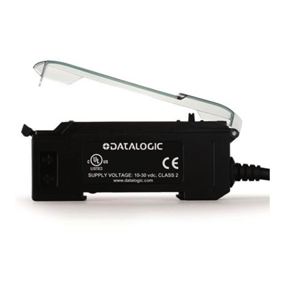
S70 Series
Advanced sensor with dual digital displays
for use with plastic and glass fiber optic assemblies
Figure 1
Outputs
Single NPN
Single PNP
Single NPN
Single PNP
Dual outputs, 1 push-pull IO-Link and 1 PNP
(complementary outputs)
Single NPN
Single PNP
10-30 VDC
Remote
Programming (N.O.)
18-30 VDC
1
2
3
4
5
6
7
2 m cable, 4-wire
Integral M8 Pico QD connector, 4-pin
Integral M8 Pico QD connector, 4-pin
PNP Version
10-30 VDC
LOAD
Load
Remote
Programming (N.O.)
1
Output LED
LO/DO Switch
RUN/PRG/ADJ Mode Switch
Lever Action Fiber Clamp
Red Signal Level
Green Threshold
+/SET/- Navigation key
1
Connector
Key
1 = Brown
2 = White
3 = Blue
4 = Black
Pico
4
2
1
3
Advertisement
Table of Contents

Related Manuals for Datalogic S70 Series


Summary of Contents for Datalogic S70 Series
- Page 1 S70 Series Advanced sensor with dual digital displays for use with plastic and glass fiber optic assemblies For complete technical information about this product, including dimensions, accessories, and specifications, see www.datalogic.com. Output LED LO/DO Switch RUN/PRG/ADJ Mode Switch Lever Action Fiber Clamp...
-
Page 2: Mounting Instructions
NOTE: If a thin fiber with less than 2.2 mm outer diameter is used, install the fiber adapter provided with the fiber assembly to ensure a reliable fit in the fiber holder. Datalogic includes the adapters with all fiber assemblies. -
Page 3: Top Panel Interface
Remote Input / IO-Link For more information about how to perform TEACH/SET methods, to program the sensor remotely, or to interface with the sensor via IO-Link, see the www.datalogic.com. Run Mode Run mode allows the sensor to operate normally and prevents unintentional programming changes. -
Page 4: Program Mode
Program Mode Program (PRG) mode allows the following settings to be programmed in the S70: Press and hold SET to exit choice list without saving S70-E1 Factory Default Settings: S70-E2 Factory Default Settings:... - Page 5 ADJUST MODE Sliding the RUN/PRG/ADJ mode switch to the ADJ position allows the user to perform Expert TEACH/SET methods and Manual Adjustment of the threshold(s). Two-Point TEACH • Establishes a single switching threshold • Threshold can be adjusted using "+" and "-" Navigation key (Manual Adjust) Two-Point TEACH is used when two conditions can be presented statically to the sensor.
-
Page 6: Dynamic Teach
2. Teach the first condition. Method Action Result a. Present the first condition. SET Button Display: Flashes "2Pt tch" then holds b. Click the SET Navigation key on "1234 2nd" a. Present the first condition Remote Input b. Single-pulse the remote input NOTE: Negative pulse for NPN models, positive pulse for PNP models. - Page 7 Dynamic TEACH and Manual Adjust Moves switching threshold value up or down to make adjustments • Slide Mode switch to ADJ to enter Adjust mode • Press "+" to increase; press "-" to decrease - GREEN display shows the switching threshold value - 2 seconds after adjustment, GREEN display will flash 3 times to confirm •...
-
Page 8: Window Set
4. Exit Dynamic TEACH. Method Action Result SET Button Click the SET Navigation key TEACH Accepted Displays alternate "PASS" with % Minimum Difference 7 , Sensor returns to Adjust mode Single-pulse remote input Remote Input TEACH Not Accepted Displays alternate "FAIL" with % Minimum Difference 7 , Sensor returns to Adjust mode 5. - Page 9 Window SET and Manual Adjust Moves sensing window center value up or down to make adjustments • Slide Mode switch to ADJ to enter Adjust mode • Press "+" to increase; press "-" to decrease - GREEN display shows the sensing window center value - 2 seconds after adjustment, the GREEN display will flash 3 times to confirm •...
-
Page 10: Light Set
Light SET • Sets a threshold a programmable % offset below the presented condition • Changes output state on any condition darker than the threshold condition • Threshold can be adjusted using "+" and "-" Navigation key (Manual Adjust) • Recommended for applications where only one condition is known, for example a stable light background with varying darker targets •... - Page 11 2. SET Sensing Condition Method Action Result • Present sensing condition SET Button Threshold Condition Accepted • Click the SET Navigation key Displays read "Lt SEt" then alternate "PASS" with % Offset 13 ; Sensor returns to Adjust mode • Present sensing condition Remote Input •...
- Page 12 Dark SET and Manual Adjust Moves switching threshold value up or down to make adjustments • Slide Mode switch to ADJ to enter Adjust mode • Press "+" to increase; press "-" to decrease GREEN display shows the switching threshold value 2 seconds after adjustment, the GREEN display will flash 3 times to confirm •...
-
Page 13: Calibration Set
Calibration SET • Sets a threshold exactly at the presented condition • Threshold can be adjusted using "+" and "-" Navigation key (Manual Adjust) A single sensing condition is presented, and the sensor positions a threshold exactly at the presented condition. When a condition lighter than the threshold is sensed, the output either turns ON or OFF, depending on the LO/DO switch setting (see LO/DO Switch in Top Panel Interface). - Page 14 2. SET Sensing Condition Method Action Result • Present sensing condition Threshold Condition Accepted SET Button • Click the SET Navigation key Displays read "cAL SEt" then flashes "PASS"; Sensor returns to Adjust mode • Present sensing condition Remote Input •...
-
Page 15: Io-Link Interface
It can be used to automatically parameterize sensors and transmit process data. For the latest IO-Link protocol and specifications, please visit the web site at www.io-link.com. The IO-Link IODD package is available on the Datalogic Website at www.datalogic.com. Troubleshooting Manual Adjustments Disabled Manual adjustments are disabled when Auto Thresholds are ON. -
Page 16: Technical Data
TECHNICAL DATA S70-x-E1 S70-x-E2 Sensing Beam: 660 nm visible red 635 nm visible red NPN/PNP models: 10 … 30 VDC Class 2 (10% max ripple) Supply Voltage: IO-Link models: 18 … 30 V dc (10% max ripple) Power and Current Consumption Standard display mode: 960 mW, Current consumption <... -
Page 17: Overall Dimensions
Dimensions in mm Datalogic S.r.l. Via S. Vitalino 13 - 40012 Calderara di Reno - Italy Tel: +39 051 3147011 - Fax: +39 051 3147205 - www.datalogic.com Datalogic reserves the right to make modifications and improvements without prior notification. 821002592 Rev.C 182859C...
Need help?
Do you have a question about the S70 Series and is the answer not in the manual?
Questions and answers