Table of Contents
Advertisement
Quick Links
Advertisement
Table of Contents

Subscribe to Our Youtube Channel
Related Manuals for Datalogic DataVS1


Summary of Contents for Datalogic DataVS1
- Page 1 Smart Vision Sensor INSTRUCTION MANUAL...
- Page 2 DATALOGIC AUTOMATION reserves the right to make modifications and improvements without prior notification. Datalogic and the Datalogic logo are registered trademarks of Datalogic S.p.A. in many countries, including the U.S.A. and the E.U. 826003842 rev.B © Copyright Datalogic 2009-2010...
-
Page 4: Table Of Contents
Available models ................................... 1 2. ELECTRICAL CONNECTIONS ................................. 2 3. OPERATING DISTANCES ................................3 4. VISION SENSOR AND CONFIGURATOR: GENERAL CHARACTERISTICS ................4 4.1. DataVS1 Vision Sensor ................................. 4 4.2. Installing the sensor................................5 4.3. VSC Configurator .................................. 7 4.4. -
Page 5: General Information
1. GENERAL INFORMATION 1.1. Conventions used in the manual This manual has been developed to provide clear and precise instructions on how to use the DataVS1 system. For more detailed information on the algorithms and techniques referenced in the manual, please find ... -
Page 6: Electrical Connections
7: blue : GROUND pin 7: ethernet TX- pin 8: red : external trigger pin 8: GROUND VSC Configurator M12 8-pole Ethernet: (DataVS1 connection) pin 1: ethernet TX+ pin 2: ethernet RX+ pin 3: ethernet RX- pin 4: not used... -
Page 7: Operating Distances
Instruction Manual DataVS1 Series 3. OPERATING DISTANCES Field range size (L x H) in mm Operating DataVS1-16-DC-S DataVS1-12-DC-S DataVS1-08-DC-x DataVS1-06-DC-S distance (mm) 17 x 12 25x20 42x30 25 x 20 40x30 60x41 33 x 25 55x40 80x55 31 x 24... -
Page 8: Vision Sensor And Configurator: General Characteristics
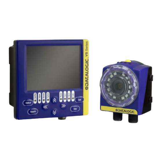
4.1. DataVS1 Vision Sensor DataVS1 is an ultra compact vision sensor which integrates all the photoelectric elements required to perform reliable control activities based on the comparison of two images. Once configured, the sensor can therefore function in a "stand-alone" mode and automatically acquires an image, controls it and then activates the outputs according to the result of the inspection. -
Page 9: Installing The Sensor
Instruction Manual DataVS1 Series LED 2: Digital output 2 (orange) LED 3: Digital output 1 (orange) LED 4: Connection to VSC configurator (green) The Teach button functions will be explained in more detail successively (Chapter 8). TEACH-IN BUTTON 4.2. - Page 10 The VSC configurator is an excellent instrument used to find the best position for the sensor. It allows the installer to view the field range of the DataVS1 in real time, and adjust its position accordingly. For this reason, it is highly recommended in difficult installation situations, to connect the sensor and the configurator to the power supply (see paragraph 4.5) and then, according to what is viewed on the...
-
Page 11: Vsc Configurator
The VSC configurator allows the installer to quickly and easily adjust the sensor settings. Once the DataVS1 has been connected, the installer can instantly access all the sensor functions, from the creation of a new inspection, to modification of parameters, from the viewing of the results and statistics to the management of digital outputs. -
Page 12: Installing The Configurator
DataVS1 Series Instruction Manual 4.4. Installing the configurator There is a slot on the back of the VSC configurator which allows the user to connect the device to a DIN Rail. During installation it is therefore sufficient to wedge the configurator on the rail and block it in place using the two white locking clips. - Page 13 Instruction Manual DataVS1 Series First, place the rubber seal around the body of the configurator paying attention to the shape of it. Rubber seal Then fix the configurator to the panel by using the two locking screws and the rubber caps.
-
Page 14: Hardware Connections
DataVS1 Series Instruction Manual Rubber caps Locking screws 4.5. Hardware connections Connect the power and I/O cable (CS-A1-06-B-xx) inserting it into the connector identified by the (PWR-I/O) icon. PWR-I/O Connect DataVS1 to the VSC using the relative connection cable (SVS-CV-VSC-xx). -
Page 15: Safety Recommendations
Never spill liquids on the devices It is strictly prohibited to use DataVS1 on systems where the safety of persons and/or things are guaranteed by the correct functioning of the device. Always RESPECT all safety rules and regulations. -
Page 16: Inspection Configuration Using Vsc
5.1. Introduction The configuration of the DataVS1 vision sensor can only be performed using the VSC unit. This chapter provides the basic procedures to follow in order to programme the sensor settings correctly. Chapters 6 and 7 provide further details on the various configuration options and a more complete panorama on the DataVS1 functions. -
Page 17: General Considerations
Instruction Manual DataVS1 Series LED ID Colour Meaning Power Green VSC Configurator correctly powered up Out 1 Orange Digital output 1 active OUT 2 Orange Digital output 2 active Link Green VSC Configurator correctly connected to the sensor Set/Net Green... - Page 18 DataVS1 Series Instruction Manual NOTE: if no inspection is saved on the DataVS1 sensor the system will display the "Vision Tool" menu from where the user can select the control to be used. For further details, please refer to the ...
- Page 19 Instruction Manual DataVS1 Series The settings that the user can modify will appear on the screen. To move from one setting to another, simply press the ARROW UP/ARROW DOWN buttons. Parameter Description Change Internal Select or deselect the option to enable/disable...
- Page 20 DataVS1 Series Instruction Manual If you wish to exit the control panel without saving the modifications, simply press the ESC button. The configurator will display a pop-up message asking the user if he wishes to save the settings. Select NO using the ARROWS and press SET to exit without saving.
- Page 21 Instruction Manual DataVS1 Series Width Control of the size of details Edge Counting of details along an edge Counting Pattern Count Counting of patterns inside an area Once the inspection tool has been selected, it is necessary to position and size the regions of interest (ROI) to be monitored.
- Page 22 DataVS1 Series Instruction Manual achieved the desired position, press the TEACH button to save the settings and return to the Setup menu. Press the ESC button to return to the Setup menu without saving the modifications (the system will request confirmation on the saving option).
-
Page 23: Step 2 - Configuration Of The Selected Inspection Tool
Instruction Manual DataVS1 Series 5.5. Step 2 - Configuration of the selected inspection tool In step 2 of the configuration process you will define the settings which will regulate the inspection tool selected in step 1. The configurator display is basically organised as seen in step 1. The settings that the user can modify are displayed on the right, whilst the rest of the screen displays the image acquired by the sensor. -
Page 24: Step 3 - Inspection Tool Function Check
DataVS1 Series Instruction Manual 5.6. Step 3 - Inspection tool function check In Monitor Mode, it is possible to check that the inspection tool settings entered during the configuration step function correctly. The user can choose from five different monitoring modes. The chart below provides a description of the main features of the five available modes with instructions on how to enable viewing. - Page 25 Instruction Manual DataVS1 Series Failure (%) % of failed inspections of the total number executed It is now possible to modify the view scale for the graph below using the buttons. RIGHT/LEFT ARROW particular: The graph is compressed along the x- axis using a factor of 10.
- Page 26 Example: Let's connect the VSC to a DataVS1 which is currently monitoring. The device will switch to Monitor Mode and display the current sensor functions. We then decide to increase the minimum acceptance threshold of the pattern match tool as sometimes the inspection does not provide the desired results.
-
Page 27: Step 4 - Output Definitions And Saving The Inspection Settings To The Sensor
Instruction Manual DataVS1 Series The standard save procedure is described in detail in paragraphs 5.7 and 6.3. It is also possible to perform a quick save of the settings as follows. Press the TEACH button when in Monitor mode. A window will appear with a summary of the modifications made to the current inspection and the memory slot currently enabled. - Page 28 DataVS1 Series Instruction Manual As seen in the image below, it is possible to assign a different behaviour to each output. Option Behaviour Part pass The output is enabled when the inspection gives a positive result. If a failure occurs it remains low.
- Page 29 It is possible to manage the sensor memory slots from the new menu displayed on the screen. DataVS1 has a total of 8 databank areas where it is possible to save 8 different inspections which can be recalled as required.
-
Page 30: Vsc Configurator: Advanced Functions
Instruction Manual VSC CONFIGURATOR: ADVANCED FUNCTIONS The previous chapter described the procedure used to create a new inspection for DataVS1. Besides the functions illustrated above, there are other user settings on the VSC configurator which can be reached from the System menu. - Page 31 Instruction Manual DataVS1 Series By default the three outputs have the following settings: OUTPUT 1: Part pass OUTPUT 2: Part pass OUTPUT 3: Part Pass To modify the behaviour of the outputs, move the cursor with the ARROWS then use SET to select the desired option.
-
Page 32: Trigger Mode
DataVS1 Series Instruction Manual 6.2. Trigger Mode The term trigger means a signal generated by an event that provokes another event. In our instance, the trigger is a signal generated by a device that triggers image acquisition. When the sensor is used to inspect moving objects, it is important to ensure that the object is inside the detection area at the precise instant the image is captured for processing. - Page 33 Instruction Manual DataVS1 Series Trigger hardware The image acquisition signal is sent by an external device (e.g. a photocell), the signal naturally has a rising and falling edge. Photocell TRIGGER Control Image OK / FAIL acquisition Measurement INSPECTION If the "Rising Edge" is selected, the image acquisition signal follows the rising edge of the external device.
-
Page 34: Load/Save
DataVS1 Series Instruction Manual It is also possible to set a delayed image acquisition compared to the trigger signal received for both hardware triggers. To set the delay value, simply use the slider found at the bottom of the screen using the RIGHT/LEFT ARROW buttons. - Page 35 Instruction Manual DataVS1 Series To select the memory bank you wish to use, move the cursor using the ARROW buttons and press the SET button to confirm. When you are on the selected memory bank, you can perform three different operations which can be recalled using the icons at the bottom of the screen: ...
-
Page 36: Fail Inspector
DataVS1 Series Instruction Manual It is possible to exit the bankset at any time by pressing the ESC button. 6.4. Fail Inspector The fail inspector is a tool which permits the user to recall the images of the last inspection failures. -
Page 37: Datavs1 Ver
To return to the main menu of the fail inspector, press the ESC key. 6.5. DataVS1 Ver. From the DataVS1 Version control panel it is possible to check the software version currently loaded on the device and its release date. To return to the main menu, press the ESC key. -
Page 38: Input Config
Instruction Manual 6.6. Input Config Input Config menu allows for selecting Digital Inspection Switching protocol and enable digital TEACH in on DataVS1. Two are the available protocols: Standard Inspection Switching Protocol without feedback from sensor. Expert Inspection Switching Protocol with feedback from sensor. -
Page 39: Protocol Selection
Instruction Manual DataVS1 Series Selection of the inspection number 8 Protocol selection To enable the standard protocol on the sensor select Basic Inspection Selection protocol radio button from Input config menu. Adjust minimum Pulse duration slider according to the width of pulses received by the sensor;... -
Page 40: Expert Protocol
DataVS1 Series Instruction Manual 6.6.2. Expert Protocol Selection of the inspection number 15 (001111) Protocol Description The Expert protocol for Inspection switching on sensor is based on an 8 phases handshake. According to this protocol the sensor makes available an ACKNOWLEDGE message, representing a feedback on the Inspection switching operation. - Page 41 Instruction Manual DataVS1 Series Note: if the number of received Trigger Input pulses is 0 or higher than 20 (number of available Memory Slots) the Inspection selection will be ignored and the sensor will resume the previous running Inspection. In this case, as feedback (phases 5, 6, 7), the sensor will give the Slot number of the previous running Inspection.
-
Page 42: Protocol Selection
DataVS1 Series Instruction Manual Protocol Selection To enable expert protocol select Advanced Inspection Switching Protocol. Adjust Minimum Pulse Duration value according to pulses duration your SVS will receive. Press TEACH button to save your configuration. 6.6.3. Digital Teach In Digital Teach In function consists in sending to the sensor a digital pulse on PIN 1. The digital pulse... - Page 43 Instruction Manual DataVS1 Series It is now possible to enter a new password consisting in a sequence of four buttons on the keyboard. Once the password has been entered, press SET to confirm. The password status switches from Disabled to Enabled.
- Page 44 DataVS1 Series Instruction Manual NOTE: when the password is Enabled, everytime the user tries to leave the monitor mode, the device requests to enter the current password. Once entered the password, the user can go to the other configuration panels in which it is possible to change the parameter settings.
-
Page 45: Controls
Instruction Manual DataVS1 Series 7. CONTROLS 7.1. Remarks These controls play a key role in the inspection process: they are used to perform controls/checks and measurement on acquired images. Entering the controls is an operating step of the inspection. The controls are the tools used to establish the inspection specifications... -
Page 46: Brightness
DataVS1 Series Instruction Manual 7.2. Brightness Description The term brightness means the "brightness" attribute of an image. Once the ROI has been set, the control will calculate the average brightness value of the pixels. Selection Positioning Select the control and press SET on the corresponding icon to create the rectangular ROI in the middle of the field range. - Page 47 Instruction Manual DataVS1 Series Result If the average brightness value inside the ROI is above the set threshold, the result will be positive (green colour indicator and ROI edge) if it is below the threshold, the result will be negative (red colour indicator and ROI edge) ...
- Page 48 DataVS1 Series Instruction Manual We can acces the Adjust mode by pressing the STATUS button. Let's increase the acceptance threshold slightly using the ARROW UP button. Now press the STATUS button to enter Monitor Mode and check that the tool functions properly.
-
Page 49: Contrast
Instruction Manual DataVS1 Series 7.3. Contrast Description The term contrast indicates the ratio between the brightness of the lightest pixel and that of the darkest pixel in an image. Images with excessively high contrast tend to have only black and white areas, whilst images with low contrast tend to look grey. - Page 50 DataVS1 Series Instruction Manual To modify the position of the ROI, move to the Move ROI icon and then press SET. It is now possible to move the ROI using the ARROW buttons. Once you have achieved the desired position, press the TEACH button to return to the Setup menu. If you wish to modify the ROI size, select the Resize ROI from the Setup menu (using the SET button again).
- Page 51 Instruction Manual DataVS1 Series We can access the Adjust mode by pressing the STATUS button. If the control fails even when there is a stamp, increase the control sensitivity a little to raise the contrast between the stamp and the envelope. To do this use the RIGHT ARROW to view the sensitivity setting and then use the ARROW UP button to increase the value.
- Page 52 DataVS1 Series Instruction Manual Let's associate output 1 to the Part Pass behaviour, output 2 to the Part Fail behaviour and output 3 Busy/Ready. Press TEACH to save the modifications. Now let's save the bank on the sensor. Enter the Bankset menu and save the inspection in memory bank 1.
-
Page 53: Position
Instruction Manual DataVS1 Series 7.4. Position Description This control allows you to detect the edge (edge detection ) and the position of the object inside the relative ROI. Based on the first derivative of the pixel brightness variation function, the maximum positive peak is identified if control is targeting a positive edge, or the maximum negative peak is identified when targeting a negative edge. - Page 54 DataVS1 Series Instruction Manual Parameters: Min Position Expected This allows you to specify the minimum value of the detectable position. Max. Position Expected This allows you to specify the maximum value of the detectable position. Sensitivity This represents the sensitivity level, that is the level of edge detection precision. Set sensitivity affects processing results;...
- Page 55 Instruction Manual DataVS1 Series Now we must perform the ROI positioning and resizing procedures: follow the instructions provided earlier during this procedure. We can access the Adjust mode by pressing the STATUS button. Let's increase the minimum position value slightly using the ARROW UP button.
-
Page 56: Width
DataVS1 Series Instruction Manual Now let's save the bank on the sensor. Enter the Bankset menu and save the inspection in memory bank 1. Press the ESC button to return to Monitor mode. 7.5. Width Description This control is also termed "gauge" and lets you measure the distance between two points. - Page 57 Instruction Manual DataVS1 Series To modify the position of the ROI, move to the Move ROI icon and then press SET. It is now possible to move the ROI using the ARROW buttons. Once you have achieved the desired position, press the TEACH button to return to the Setup menu. If you wish to modify the ROI size, select the Resize ROI from the Setup menu (using the SET button again).
- Page 58 DataVS1 Series Instruction Manual Result If the calculated width value is between the minimum and maximum values set by the user, the control gives a positive result. If no edges are found, or their reciprocal distances are not within the two defined limits, the result will be negative.
- Page 59 Instruction Manual DataVS1 Series The sensor now behaves as required. As the result is satisfying, press STATUS again and move on to defining the behaviour of the outputs. Let's associate output 1 to the Part Pass behaviour and output 2 to the Busy/Ready behaviour.
-
Page 60: Edge Count
DataVS1 Series Instruction Manual 7.6. Edge count Description This control allows you to detect all the edges (edge detection ) that are within a specific ROI. Based on the first derivative of the pixel brightness variation function, the maximum positive peak is identified if control is targeting a positive edge, or the maximum negative peak is identified when targeting a negative edge. - Page 61 Instruction Manual DataVS1 Series Parameters: Min edges Expected This allows you to specify the minimum number of detectable edges. Max. edges Expected This allows you to specify the maximum number of detectable edges. Sensitivity This represents the sensitivity level, that is the level of edge detection precision. Set sensitivity affects processing results;...
- Page 62 DataVS1 Series Instruction Manual The ROI now has to be suitably resized and positioned: follow the instructions provided earlier during this procedure. We access the Adjust mode by pressing the STATUS button. Let's increase the minimum edge limit value to 3 using the ARROW UP button.
-
Page 63: Pattern Match
Instruction Manual DataVS1 Series Let's associate output 1 to the Part Pass behaviour and output 2 to the Part Fail behaviour. Press TEACH to save the modifications. Now let's save the bank on the sensor. Enter the Bankset menu and save the inspection in memory bank 1. - Page 64 DataVS1 Series Instruction Manual Selection Positioning The positioning and resizing of the ROI for the Pattern Match control is different compared to what we have seen for the other inspection tools. During the setup phase, it is in fact necessary to define the pattern to be searched inside the image and also the section of the area which has to be searched.
- Page 65 Instruction Manual DataVS1 Series Parameters Expected Threshold used to assess the result. This indicates to what extent the detected area in the ROI must match the sample image in order to be considered as valid (100% perfect match, 0% ... ).
- Page 66 DataVS1 Series Instruction Manual We now go to Adjust mode by pressing the STATUS button. Let's increase the expected value slightly using the ARROW UP button as we want exact replicas of the original logo. Now press the STATUS button to enter Monitor Mode and check that the tool functions properly.
-
Page 67: Ocv
Instruction Manual DataVS1 Series Press the ESC button to return to Monitor mode. 7.8. Description The OCV (Optical Character Verification) operator is able to check whether the text contained in an image is identical to that in the reference image. - Page 68 DataVS1 Series Instruction Manual To modify the position of the ROI, move to the Move ROI icon and then press SET. It is now possible to move the ROI using the ARROW buttons. Once you have achieved the desired position, press the TEACH button to return to the Setup menu. If you wish to modify the ROI size, select the Resize ROI from the Setup menu (using the SET button again).
- Page 69 Instruction Manual DataVS1 Series Example Let's add an "OCV" control to the current inspection tool, so we can check that a web address is printed correctly on boxes. Let's select "OCV" from the Controls menu and then press the SET button.
- Page 70 DataVS1 Series Instruction Manual The sensor now behaves correctly. As the result is satisfying, press STATUS again and move on to defining the behaviour of the outputs. Let's associate output 1 to the Part Pass behaviour and output 2 to the Part Fail behaviour. Press TEACH to save the modifications.
-
Page 71: Pattern Count
Instruction Manual DataVS1 Series 7.9. Pattern Count Description The term pattern match indicates a process where sample image is recognised by searching for the matching brightness matrix in the target image. (Pattern Match Once ROI is fixed, the inspection looks for the target object within a specific area of the image and determines its position and number of matching objects found. - Page 72 DataVS1 Series Instruction Manual To swap from one area to the other for editing purposes, simply press SET. The outline of the currently selected area will flash and ROI label is highlighted in red. To change the size of the two ROIs it is necessary to set onto Size ROI icon and press SET. It is now possible to resize the ROIs at will using the ARROW keys.
- Page 73 Instruction Manual DataVS1 Series Select “Pattern Count” from the controls menu and press SET. A rectangular default ROI shall be created at image center. The ROI shall then be sized and positioned as required: to do this, we use the above-described options.
- Page 74 DataVS1 Series Instruction Manual The sensor response is correct. Since the result is satisfactory, press again STATUS and set up the outputs. Assign Part OK to output 1 and Part Fail to output 2. Press TEACH to save edited settings.
-
Page 75: Teach Button
Instruction Manual DataVS1 Series 8. TEACH BUTTON The Teach button located on the upper part of the sensor allows you to reboot the device in Recovery mode. This function is needed to update the firmware of the sensor. To enable the recovery procedure, boot the device whilst holding the TEACH button down until the output LEDs (the two central ones) start to flash;... -
Page 76: Checks And Periodic Maintenance
Do not dismantle the device or make any changes to its components or the warranty will become null and void. Datalogic may not be held liable for damage to persons or property resulting from failure to comply with the provisions reported herein. -
Page 77: Technical Data
11 ms (30 G) 6 shocks for each axis (EN60068-2-27) Housing material: Aluminium alloy / ABS Mechanical protection: IP50 Connections: 2 x M12 8 pole A-code Weight: 125 g (DataVS1); 170 g (VSC) IMAGE SENSOR Technology: CMOS Supply voltage: 3.3 V Format: ⅓-inch Pixel matrix:... -
Page 78: Overall Dimensions
DataVS1 Series Instruction Manual 12. OVERALL DIMENSIONS... -
Page 79: Accessories
Instruction Manual DataVS1 Series 13. ACCESSORIES ST-5066 ST-5068 U-shaped bracket to adjust the angle L-shaped bracket to fix the sensor at a 90° angle MOUTING KIT Base... - Page 80 VSC Configurator 959941040 DataVS1-VSC 2m SVS-VSC connection cable 95A901360 SVS-CV-VSC-02 4m SVS-VSC connection cable 95A901370 SVS-CV-VSC-04 DataVS1 UPDATING KIT DataVS1 Updating Kit 95A901540 L-shaped fixing bracket for 90° mounting 95A901320 SVS-ST-5068 U-shaped fixing bracket for angle adjustment 95A901330 SVS-ST-5066 Mounting kit...
-
Page 81: Tutorial
(grey scale) information The maximum resolution of the DataVS1 sensor is 640 × 480 pixel. This means that the acquired images will be processed by a personal computer as 640×480 element matrixes (307200 values). Each element is identified by its location in the matrix, i.e. by specifying column and line and considering the first element in the top left corner as the origin (in the matrix shown above, this would be the pixel with brightness equal to 20). -
Page 82: Machine Vision
In the case of the DataVS1 system, the sensor "view" option allows you to inspect the product to: ... -
Page 83: Lighting Options
Instruction Manual DataVS1 Series 14.4. Lighting options Ring light This technique is suitable for a broad range of applications. The illuminator is mounted directly on the sensor and can illuminate any object placed in front of it. It provides diffused illumination over a small area. -
Page 84: Binarization
DataVS1 Series Instruction Manual 14.5. Binarization This is a process that converts any given image to a two-level image (in our instance, black and white). Conversion is based on a threshold that classifies the individual pixels as "level 255" (or "white") or "level 0"... -
Page 85: Edge / Edge Detection
From an operational viewpoint, what happens is that the system detects the difference in the brightness of adjacent pixels compared to a certain threshold value. This variation on the DataVS1 system is detected along a direction: Let us consider the portion of image inside the rectangle that contains the plotted arrow (length L and... -
Page 86: Inspection Times
DataVS1 Series Instruction Manual 14.7. Inspection times Total inspection duration depends on three factors: Exposure time ( Acquisition time Processing time Exposure time: time period during which the acquisition device is exposed to light. The longer the exposure time, the greater the quantity of light entering the device. -
Page 87: Exposure
Instruction Manual DataVS1 Series 14.9. Exposure Exposure time determines how long the image acquisition device must remain exposed to light. Image quality depends on this parameter, that is determined based on: Lens aperture; Exposure. The term Lens aperture denotes the ratio of lens length to lens width. A longer lens (where light travels a longer distance) will have a higher ratio and will provide less strength. -
Page 88: Glossary
DataVS1 Series Instruction Manual 15. GLOSSARY Algorithm: a combination of instructions that lead to the solution of a problem through a series of steps; Area of inspection: this corresponds to the area of interest acquired by the sensor, or part of the same, which is then processed;...
Need help?
Do you have a question about the DataVS1 and is the answer not in the manual?
Questions and answers