
Related Manuals for Campbell CWB100


Summary of Contents for Campbell CWB100
- Page 1 Wireless Sensor Network Revision: 11/17 C o p y r i g h t © 2 0 1 0 - 2 0 1 7 C a m p b e l l S c i e n t i f i c , I n c .
- Page 3 Limited Warranty “Products manufactured by CSI are warranted by CSI to be free from defects in materials and workmanship under normal use and service for twelve months from the date of shipment unless otherwise specified in the corresponding product manual. (Product manuals are available for review online at www.campbellsci.com.) Products not manufactured by CSI, but that are resold by CSI, are warranted only to the limits extended by the original manufacturer.
- Page 4 Campbell Scientific company serves your country. To obtain a Returned Materials Authorization (RMA) number, contact CAMPBELL SCIENTIFIC, INC., phone (435) 227-9000. Please write the issued RMA number clearly on the outside of the shipping container. Campbell Scientific’s shipping address is: CAMPBELL SCIENTIFIC, INC.
- Page 5 Periodically (at least yearly) check electrical ground connections. • WHILE EVERY ATTEMPT IS MADE TO EMBODY THE HIGHEST DEGREE OF SAFETY IN ALL CAMPBELL SCIENTIFIC PRODUCTS, THE CUSTOMER ASSUMES ALL RISK FROM ANY INJURY RESULTING FROM IMPROPER INSTALLATION, USE, OR MAINTENANCE OF TRIPODS, TOWERS, OR ATTACHMENTS TO TRIPODS AND TOWERS SUCH AS SENSORS, CROSSARMS, ENCLOSURES, ANTENNAS, ETC.
-
Page 7: Table Of Contents
PDF reader bookmarks tab for links to specific sections. 1. Introduction ..............1 2. Precautions ..............1 3. Initial Inspection ............1 4. Overview ..............2 CWB100 Wireless Base Station ............2 Wireless Sensors .................. 2 4.2.1 CWS220 Wireless Infrared Radiometer........3 4.2.2 CWS655 Wireless Soil-Water Probe .......... - Page 8 Battery Characteristics ..............D-1 Effect of Polling Interval and Repeaters on Battery Life ....D-1 E. Using SDI-12 with a Wireless Sensor Network ..E-1 Configure the CWB100 ..............E-1 Configure Wireless Sensors ............. E-1 Available SDI-12 Commands ............E-2 E.3.1 Address Query Command (?!) ..........
- Page 9 E.4.1 Basic SDI-12 CRBasic Example Program ........ E-7 E.4.2 SDI-12 CRBasic Example Program with Diagnostics ....E-7 Figures 4-1. CWB100 Wireless Base Station ............2 4-2. CWS220 Wireless Infrared Radiometer ..........3 4-3. CWS655 Wireless Water Content Reflectometer ........ 4 4-4.
- Page 10 Table of Contents...
-
Page 11: Introduction
The base station serves as the gateway to the network, communicating with a Campbell Scientific CR800-series, CR1000, or CR3000 datalogger via a control port as specified in the CRBasic CWB100() instruction. The base station communicates with all wireless sensors in the network using its own sensor network protocol. -
Page 12: Overview
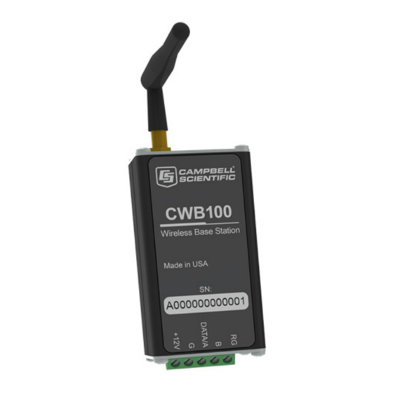
CWB100 Wireless Base Station In the wireless sensor network, the CWB100 serves as the master radio and the interface between the datalogger and the wireless sensors. It holds information for the routes to all the sensors in the network and is responsible for polling the sensors. -
Page 13: Cws220 Wireless Infrared Radiometer
FIGURE 4-2. CWS220 Wireless Infrared Radiometer 4.2.2 CWS655 Wireless Soil-Water Probe The CWS655 is based on Campbell Scientific’s CS655 Soil Water Content Reflectometer. It returns nine measurements. Default measurement names and meanings are shown in Appendix C.2, CWS655 Measurements (p. -
Page 14: Cws900 Configurable Wireless Sensor Interface
Wireless Sensor Network transmission line. A differential oscillator circuit is connected to the rods. An oscillator state change is triggered by the return of a reflected signal from one of the rods. The two-way travel time of the oscillator-induced electromagnetic waves on the rod increases with increasing volumetric water content of the surrounding media, hence the name water content reflectometer. -
Page 15: Specifications
Wireless Sensor Network FIGURE 4-4. CWS900 Wireless Sensor Interface Specifications CWB100 Operating Temperature: –25 to 50 °C (–13 to 122 °F) Operating Relative Humidity: Store and use in a noncondensing (desiccated) environment. Power Requirements Voltage: 4.5 to 22 Vdc Typical Current Drain Standby: <1 mA... -
Page 16: Cws220 Specifications
Wireless Sensor Network CWS220 Specifications TABLE 5-1. Temperature Accuracy, Uniformity, and Repeatability Temperature Absolute Range Accuracy Uniformity Repeatability –10 to 65 °C ±0.2 °C ±0.1 °C ±0.05 °C –40 to 70 °C ±0.5 °C ±0.3 °C ±0.1 °C Response Time: <1 s to changes in target temperature Wavelength Range: 8 to 14 µm (corresponds to atmospheric... -
Page 17: Cws900 Specifications
Wireless Sensor Network Operating Relative Humidity: 0 to 100% Weather Resistance: IP67 rating for sensor and battery pack (battery pack must be properly installed; each sensor is leak tested) Power: 2 AA batteries with a battery life of 1 year, assuming sensor samples taken every 10 minutes Average Current Drain:... -
Page 18: Internal Radio
Does not include sensor and measurement noise, or external bridge resistor errors. Internal Radio Radio Type: 25 mW Frequency Hopping Spread Spectrum (FHSS) Frequency 902 – 928 MHz: CWB100, CWS220, CWS655, CWS900 CWB100A, CWS220A, CWS655A, CWS900A 868 MHz: CWB100E, CWS220E, CWS655E, CWS900E FHSS Channels 902 – 928 MHz:... -
Page 19: Installation
USB Cable, Type A Male to Type B Male (pn 17648) • Wireless Sensor Planner, available for download at • www.campbellsci.com/cwb100 -or- Network Planner, included in LoggerNet CWB100 USB Driver, available at • www.campbellsci.com/cwb100 A205 CWS Interface USB Driver, available at • www.campbellsci.com/a205 Compatible datalogger with a computer connection •... -
Page 20: Adding Devices To The Wireless Sensor Network
To create links, click the Link Tool icon on the toolbar (shown below). Select the CWB100 and the click on a sensor to complete a link. An Add Link Between Devices window will open showing the link. Click OK to accept the... -
Page 21: Configure Devices
Wireless Sensor Network The link is now represented on the Drawing Canvas by a line between the base station and the sensor. Repeat for each sensor. When linking to a CWS900, an additional window opens showing the addresses of the base station and the settings of the CWS900. Click Apply to accept the settings. -
Page 22: Configuring The Cwb100
Select Program settings for CWB100_1:CWB100 in the list, then click Click Here in the panel below. When the Setup Dialog window opens, connect the CWB100 to a USB port on your computer using the included cable (pn 17648). Click Serial Port. Select the port named CWB100 (COMxx). Click OK. -
Page 23: Configuring A Wireless Sensor
Wireless Sensor Network After the new settings have been sent to the device, the Settings have Been Applied window opens. Options are available for saving the settings to a XML file, printing the settings, and comparing the settings to another XML file. When finished with these actions, click OK. -
Page 24: Connecting A Computer To A Sensor
Wireless Sensor Network Remove the battery pack from the sensor. Wait 15 seconds. Connect the A205 to the four-pin connector near the top of the sensor. The A205 label should be facing toward the sensor antenna. Connect the A205 to the computer with the USB cable as shown in FIGURE 6-2. -
Page 25: Send The Sensor Configuration File To The Datalogger
Wireless Sensor Network options are available for saving the settings to a XML file, printing the settings, and comparing the settings to another XML file. When finished with these actions, click OK. The Setup button must be pressed to enable communications NOTE between the wireless sensor and computer. -
Page 26: Programming The Datalogger
(p. A-1) 6.2.1 Datalogger Scan Rate The CWB100 synchronizes the network measurement rate to match the main datalogger scan rate, so the datalogger scan rate must give enough time for all sensors to transmit their data. When creating a program at first, set the scan rate to allow for 1 minute per sensor. -
Page 27: Values Transmitted By Cws Sensors
The datalogger has failed after three consecutive attempts to –1 collect data from the base station. –2 The signature verifying communication is wrong. The signature of the names held by the datalogger is different –3 from the signature of names held by the CWB100. -
Page 28: Wiring The Cwb100
The installation can be tested in the office, but remove power from the CWB100 and all sensors before transporting to the field. This will erase the routing table and halt network traffic while in transit. The routing table must be erased because the routes found in the lab will likely be different from the routes used in the field. -
Page 29: Connecting Sensors To The Cws900
Once the radio link is established, the red sensor LED will flash, and the sensor will be established on the CWB100 routing table. During this process the red LED on the CWB100 stays on longer than usual, indicating that it is receiving a transmission. Afterward, the blue sensor LED will flash when the sensor makes a measurement, and the red sensor LED will flash when the data is transmitted to the CWB100. -
Page 30: Verify That Data Is Being Transmitted
, for (p. B-1) details. Verify that Data is being Transmitted After the sensors have established links to the CWB100 radio, verify that data is being received by looking at the CWSDest array in datalogger support software. Operation The CWB100() instruction sets the sensor measurement and polling interval. -
Page 31: Rf Connection Type Setting
If a sensor has not responded to six polls by the CWB100 and it has been more than two hours since the last communication, the CWB100 will stop polling that sensor. -
Page 32: Advanced Programming
Wireless Sensor Network It can be useful to change this setting from its default in certain instances. For example, if the wireless sensor network is composed of many sensors that are all within range of the base, changing it to Connect Direct to Base will force all the connections to the base. -
Page 33: Arrayindex() Function
Using this configuration string example, index 6 of the destination array would be the EC field of the CWS655 with the radio address of 18534B402008. The configuration string may be written directly in the CWB100() instruction or in a separate text file that is stored on the datalogger. The configuration strings generated by Wireless Sensor Planner and Network Planner are written to text files. -
Page 34: Cwb100Routes() Instruction
7.3.3 CWB100Routes() Instruction Use the CRBasic instruction CWB100Routes() to view the routes used by the wireless sensors to transmit their data to the CWB100 base station. For each wireless sensor in the network, the instruction returns the sensor radio address, the sensor name, any routing hops to the base, and the time required (in seconds) for the last poll. -
Page 35: Cwb100Rssi() Instruction
NAN. The instruction has the following format: CWB100RSSI (Port) The Port parameter is the datalogger port communicating with the CWB100. Because it requires an additional poll, only use the CWB100RSSI() instruction occasionally to increase battery life (see Section 6.2, Programming the Datalogger ). -
Page 36: Cwb100Diagnostics() Instruction
(CWBPort,CWSDiag) The CWBPort parameter is the datalogger port communicating with the CWB100. The CWSDiag parameter is the array of type Long that will hold the five values returned. These five values are shown below: CWSDiag(1) = Number of sensors discovered by the base... -
Page 37: Troubleshooting
Checking Sensor Links to the Base Station When the sensor has established a route to the base, that route is held in the CWB100 routing table. To access that table, use the CWB100Routes() instruction. See Section 7.3.3, CWB100Routes() Instruction , for details. -
Page 38: Checking Sensor Signal Strength
Removing a Wireless Sensor from the Network If a sensor has not responded to six polls by the CWB100 and it has been more than two hours since the last communication, the CWB100 will stop polling that sensor. -
Page 39: Replacing A Wireless Sensor In The Network
Wireless Sensor Network Replacing a Wireless Sensor in the Network If a wireless sensor in the network needs to be replaced, the CWB100 treats the replacement sensor as a new sensor because it has a different radio address than the original sensor. Data from the replacement sensor will be saved to a different position in the final storage data file with field names that include the tilde (~) character. - Page 40 0. The measurement names in the datalogger do not match the names stored in the CWB100 base station. This is a rare error message that should disappear after the datalogger has made its second attempt to communicate with the CWB100 base station. On the second attempt,...
- Page 41 CWB100 base its version of the names and then the name signatures from both devices will match. Symptom: Values in the destination array are NAN. This indicates that the CWB100 is unable to get data from the wireless sensor. •...
- Page 42 Wireless Sensor Network...
-
Page 43: Crbasic Example Programs
Though written for CR800-series dataloggers, the following example programs can be used directly with CR1000 and CR3000 dataloggers. By changing the port used in the CWB100() instruction, they can be used with CR6-series dataloggers as well. The wiring table below is used in each example. -
Page 44: Program With Diagnostics
The following program reports all available diagnostics for a wireless sensor network: battery voltages, routes, signal strength, and network diagnostics. It measures a CWS655 and a CWS900 connected to a Campbell Scientific 109 Temperature Probe. Sensor measurements are made every 10 minutes, while signal strength is measured every 60 minutes. -
Page 45: Using Device Configuration Utility For Sensor Setup
Once Device Configuration Utility connects to the sensor, enter the address of the CWB100 in the Base Station Address field. If configuring a CWS900, select the type of measurement the sensor will make from the Measurement... - Page 46 Appendix B. Using Device Configuration Utility for Sensor Setup Click Apply to apply the changes. A configuration summary will be displayed. Save the configuration information if desired, and then click OK to close the window. Device Configuration Utility can also be used to check sensor measurements. While connected to the sensor, Device Configuration Utility triggers a measurement of the wireless sensor every 5 seconds.
- Page 47 Appendix B. Using Device Configuration Utility for Sensor Setup...
- Page 48 Appendix B. Using Device Configuration Utility for Sensor Setup...
-
Page 49: Wireless Sensor Measurement Names And Meanings
Appendix C. Wireless Sensor Measurement Names and Meanings Default measurement names are shown in Wireless Sensor Planner, Network Planner, and Device Configuration Utility software. Custom names may be assigned to the measurements with Wireless Sensor Planner or Network Planner. It is good practice to keep the measurement names short. The default names, meanings, and measurement units for each sensor and configuration are listed in the following sections. -
Page 50: Cws900 Measurements
Appendix C. Wireless Sensor Measurement Names and Meanings C.3 CWS900 Measurements Depending on the configuration, the CWS900 returns 4 to 12 values. TABLE shows all configuration options and which outputs each gives. TABLE shows the default names of the outputs and provides a description for each. TABLE C-1. -
Page 51: Cws900 Measurement Names
Appendix C. Wireless Sensor Measurement Names and Meanings TABLE C-2. CWS900 Measurement Names Default Name Meaning Units Internal temperature of wireless sensor °C Battery voltage of wireless sensor Volts Unitless, ranging from 0 Signal strength of last received radio transmission (no signal) to 32 (full signal) Volts, may need additional... -
Page 52: Wind Vector Calculations
Appendix C. Wireless Sensor Measurement Names and Meanings TABLE C-2. CWS900 Measurement Names Default Name Meaning Units Wind speed maximum during last polling interval. Calculated from WSMX a running average of three successive, one-second wind speed measurements. Wind speed minimum during last polling interval. Calculated from WSMN a running average of three successive, one-second wind speed measurements. - Page 53 Appendix C. Wireless Sensor Measurement Names and Meanings Calculations: FIGURE C-1. Input Sample Vectors In FIGURE C-1, the short, head-to-tail vectors are the input sample vectors described by s and Θ , the sample speed and direction, or by Ue and Un , the east and north components of the sample vector.
- Page 54 Ue = (ΣUe Un = (ΣUn Resultant mean wind direction, Θu: Θu = Arctan (Ue/Un) Standard deviation of wind direction, σ(Θu), using Campbell Scientific algorithm: σ(Θu) = 81(1–U/S) The algorithm for σ(θu) is developed by noting (FIGURE C-3) that where Θ...
-
Page 55: Standard Deviation Of Direction
Appendix C. Wireless Sensor Measurement Names and Meanings FIGURE C-3. Standard Deviation of Direction The Taylor Series for the Cosine function, truncated after 2 terms is: Θ ≅ − Θ For deviations less than 40 degrees, the error in this approximation is less than 1%. - Page 56 Appendix C. Wireless Sensor Measurement Names and Meanings The final form is arrived at by converting from radians to degrees (57.296 degrees/radian). σ Θ − −...
-
Page 57: Battery Life
Appendix D. Battery Life D.1 Battery Characteristics The battery life of the CWS wireless sensors is a function of the polling interval, repeater usage, type of batteries, and temperature. The types of batteries that can be used in the sensors are AA sized alkaline, Lithium, NiMH, or NiCd. - Page 58 Appendix D. Battery Life TABLE D-1. Approximate Battery Life Expectancy 5 Min 10 Min 15 Min Sensor and Connection Polling Polling Polling CWS900 with 109 Temperature 15 months 21 months 24 months Probe or CWS655 Same as above, used as a 8 months 12 months 15 months...
-
Page 59: Using Sdi-12 With A Wireless Sensor Network
CR300. For more information about the SDI-12 protocol, visit www.sdi-12.org. E.1 Configure the CWB100 Connect to the CWB100 in Device Configuration Utility. First select the wireless sensor from the Device Type list. Then, follow the instructions shown in the window on the right. -
Page 60: Available Sdi-12 Commands
Appendix E. Using SDI-12 with a Wireless Sensor Network Note the number of values the sensor returns, not counting RSSI. Click Apply. Repeat for each wireless sensor. E.3 Available SDI-12 Commands TABLE shows all available SDI-12 commands and their responses. Information on each of these commands is given in following sections. -
Page 61: Address Query Command
(p. E-6) E.3.1 Address Query Command (?!) The response to the Address Query command (?!) is the address of the first sensor in the CWB100 routing table. If no sensors have been discovered, it will return an empty line. Command... -
Page 62: Start Measurement Commands With Cyclic Redundancy Check (Amc
Appendix E. Using SDI-12 with a Wireless Sensor Network values each. Subsequent commands only serve to pick up additional values and do not trigger an exchange with the sensor. When the aM! is issued, the sensor responds with its address, the time until the data will be available, and how many values the data will include. -
Page 63: Send Identification Command (Ai
Value 3 +21.62282 Value 4 +2.770481 E.3.7 Send Identification Command (aI!) The response to the Send Identification command (aI!) is the model and version of the CWB100 base station and the radio address of the sensor. Command Response Format: allccccccccmmmmmmvvvxxxxxxxxxxxx Example:... -
Page 64: Get Sensor Field Names (Ax1
Appendix E. Using SDI-12 with a Wireless Sensor Network Command Response Format: aX0! a:<address> Example: 2X0! 2:12530A401396 The above example shows a sensor addressed 2 responding with the address of the base station it is linked to. E.3.10 Get Sensor Field Names (aX1!) The Get Sensor Field Names (aX1!) command is used to retrieve the field names for a sensor. -
Page 65: Basic Sdi-12 Crbasic Example Program
The following program reports all available diagnostics for a wireless sensor network communicating with the SDI-12 protocol: battery voltages, routes, signal strength, and network diagnostics. It measures a CWS655 and a CWS900 connected to a Campbell Scientific 109 Temperature Probe. The CWS655 SDI-12 address is 5, and the CWS900... -
Page 66: E-2. Sdi-12 Program With Diagnostics
Appendix E. Using SDI-12 with a Wireless Sensor Network address is 8. Sensor measurements are made every 10 minutes, while signal strength is measured every 60 minutes. A Boolean variable called DiagTest is available to manually force the signal strength measurement. Sensor routes and network diagnostics are reported every scan. - Page 68 Santo Domingo, Heredia 40305 SOUTH AFRICA COSTA RICA • cleroux@csafrica.co.za • info@campbellsci.cc www.campbellsci.co.za www.campbellsci.cc Campbell Scientific Southeast Asia Co., Ltd. Campbell Scientific Ltd. 877/22 Nirvana@Work, Rama 9 Road Campbell Park Suan Luang Subdistrict, Suan Luang District 80 Hathern Road Bangkok 10250...
Need help?
Do you have a question about the CWB100 and is the answer not in the manual?
Questions and answers