Table of Contents
Advertisement
Quick Links
Advertisement
Table of Contents

Related Manuals for Campbell CS240


Summary of Contents for Campbell CS240
- Page 1 Revision: 08/2020 Copyright © 2017 – 2020 Campbell Scientific, Inc.
-
Page 2: Table Of Contents
7.4.1.2 Converting resistance measurement to temperature 7.4.2 CS240DM programming 8. Operation 8.1 Electrical noisy environments 8.2 Long cable lengths 8.2.1 CS240 cable resistance/long cable lengths 8.2.2 CS240DM long cable lengths 8.3 Modbus register map 8.4 CS240DM and Device Configuration Utility 9. Maintenance and troubleshooting 9.1 Maintenance... - Page 3 9.2 Troubleshooting Appendix A. Importing Short Cut code into CRBasic Editor Appendix B. Example programs B.1 CS240 two-wire configuration programs B.2 CS240 four-wire configuration programs B.3 CS240DM program Appendix C. Sensor material properties C.1 3M F9473PC adhesive Table of Contents - ii...
-
Page 4: Introduction
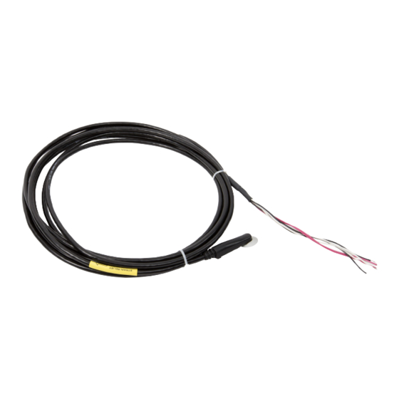
(PV) module temperature but also can be used to measure the surface temperature of other devices. The CS240 can be measured with a 2-wire or 4-wire configuration and is compatible with most Campbell Scientific data loggers. The CS240DM has a digital RS-485 output that can be directly read by a MeteoPV, CR6, CR1000X, or Modbus RTU RS-485 network. -
Page 5: Initial Inspection
1. Open Short Cut and click Create New Program. 2. Double-click the data logger model. 3. In the Available Sensors and Devices box, type CS240. You can also locate the sensor in the Sensors > Temperature folder. Double click the sensor model. The surface temperature defaults to degree C. - Page 6 4. Click on the Wiring tab to see how the sensor is to be wired to the data logger. Click OK after wiring the sensor. 5. Repeat steps three and four for other sensors you want to measure. Click Next. CS240 and CS240DM PT-1000 Class A, Back-of-Module Temperature Sensors...
- Page 7 9. If the sensor is connected to the data logger, check the output of the sensor in the data logger support software data display in LoggerNet, RTDAQ, PC400, or PC200W to make sure it is making reasonable measurements. CS240 and CS240DM PT-1000 Class A, Back-of-Module Temperature Sensors...
-
Page 8: Overview
5. Overview The CS240 and CS240DM are surface mountable platinum resistive thermometers (PRT) that measure back-of-module temperature for solar energy applications. They use a precision PT-1000 class A PRT to provide the highest level of accuracy. To withstand the harsh treatment commonly... -
Page 9: Specifications
Rugged design holds up in harsh conditions and conduit installations Self-adhesive backing for easy mounting lasts decades CS240 has 2-wire or 4-wire configurations to satisfy accuracy even at long cable lengths CS240 compatible with Campbell Scientific CRBasic data loggers: CR6, CR3000, CR1000X,... - Page 10 AWM 10012 1000V 105 °C Filler: Fibrillated polypropylene as required for uniform round construction. Drain: 24 AWG (7/32) tinned copper (cabled, touching foil) Shield: Aluminum/mylar (100% coverage, 25% minimum overlap, foil facing in) CS240 and CS240DM PT-1000 Class A, Back-of-Module Temperature Sensors...
-
Page 11: Installation
PV module. 7.2 Mounting/cable strain relief CAUTION: Before mounting, the installers need to wash their hands and then clean the back of the PV module or other device with ethyl alcohol. CS240 and CS240DM PT-1000 Class A, Back-of-Module Temperature Sensors... -
Page 12: Adhesive Mounting Strip
5. Place the two other strips of tape on the ends of the sensor disk, perpendicular to the first piece of tape and parallel to the cable then rub the tape surface into the module surface. FIGURE 7-2 (p. 10). CS240 and CS240DM PT-1000 Class A, Back-of-Module Temperature Sensors... - Page 13 FIGURE 7-1. Strain relief label on the cable FIGURE 7-2. Proper tape usage CS240 and CS240DM PT-1000 Class A, Back-of-Module Temperature Sensors...
-
Page 14: Strain Relief Of Cs240Dm Analog-To-Digital Module
(p. 11) provides the circuit diagrams for the CS240 2-wire configuration. FIGURE 7-4 (p. 12) provides the circuit diagram for the CS240DM or the CS240 4-wire configuration. FIGURE 7-3. 2-Wire Circuit Diagram CS240 and CS240DM PT-1000 Class A, Back-of-Module Temperature Sensors... -
Page 15: Cs240-To-Data-Logger Wiring
The 4-wire configuration eliminates resistance due to cable length and is the most accurate way to measure this sensor. The CS240 is shipped ready for the 2-wire configuration. The wires used only for the 4-wire configuration are taped to the side of the cable. -
Page 16: Cs240Dm Wiring
Table 7-2: Wire color and data logger connection for the CS240 4-wire configuration Wire color Wire function Data logger connection terminals U configured for differential high analog input White Analog voltage output DIFF H (differential high, analog-voltage input) U configured for differential low analog input... -
Page 17: Data Logger Programming
Long cable lengths (p. 16) prior to programming your data logger. 7.4.1 CS240 programming The CS240 program needs to measure the resistance of the CS240 then convert that resistance measurement to temperature. 7.4.1.1 Resistance measurement BrHalf4W CRBasic instructions used to measure resistance are the... -
Page 18: Converting Resistance Measurement To Temperature
Programming basics for the CR6 and CR1000X data loggers are provided in this section. Contact Campbell Scientific if using a data logger that requires an MD485 interface. A CR6 or CR1000X data logger programmed as a Modbus Master can retrieve the values stored in... -
Page 19: Operation
AC power lines, pumps, power inverters, and motors can be the source of electrical noise. If the CS240 sensor or data logger is located in an electrically noisy environment, the CS240 sensor should be measured with the 60 or 50 Hz rejection option. -
Page 20: Cs240Dm Long Cable Lengths
FIGURE 8-1. BrHalf (2-wire half bridge) measurement error as a function of cable length The heat shrink label on the CS240 cable provides the cable resistance (ohms). When using the 2-wire configuration, subtract this cable resistance from the measured resistance value. The value included on the label is calculated with the following equation: Cable resistance = 0.0274 ohm/feet x cable length (in feet) -
Page 21: Modbus Register Map
Use low capacitance, low resistance, screened cable (as fitted by Campbell Scientific) to reach distances of several hundred meters. Ensure that the power ground cable has low resistance and is connected to the same ground reference as the data logger control terminals. -
Page 22: Cs240Dm And Device Configuration Utility
8.4 CS240DM and Device Configuration Utility Device Configuration Utility (DevConfig) is bundled in Campbell Scientific’s data logger support software and can also be acquired, at no cost, from www.campbellsci.com/downloads. DevConfig can be used to change the CS240DM settings, view stored values, and update the CS240DM operating system (OS). - Page 23 The settings are changed in the Holding Registers tab. Except for the Modbus Address, the default values are typical for most Modbus systems and therefore rarely need to be changed. The values stored are shown in the Input Registers tab. CS240 and CS240DM PT-1000 Class A, Back-of-Module Temperature Sensors...
-
Page 24: Maintenance And Troubleshooting
Symptom: Unstable Temperature Make sure the clear shield or white/green striped wire is connected to data logger ground, and the data logger is properly grounded. For the CS240, try using the 60 or 50 Hz integration options and/or increasing the settling time. -
Page 25: Appendix A. Importing Short Cut Code Into Crbasic Editor
Block. This adds an apostrophe (') to the beginning of each of the highlighted lines, which instructs the data logger compiler to ignore those lines when compiling. The Comment Block feature is demonstrated at about 5:10 in the CRBasic | Features video CS240 and CS240DM PT-1000 Class A, Back-of-Module Temperature Sensors... -
Page 26: Appendix B. Example Programs
(p. 23) provides wiring for the CS240 four-wire configuration programs (p. 28), and Table B-3 (p. 24) provides wiring for the CS240DM program (p. 31). Table B-1: Wiring for CS240 2-wire configuration example programs CR1000X Wire color Wire function CR300 terminals CR6 terminals terminals... -
Page 27: Cs240 Two-Wire Configuration Programs
EndTable 'Main Program BeginProg 'Main Scan Scan (5,Sec,1,0) 'CS240 (2-wire) Class A RTD Back of PV Module Temperature Sensor 'measurement 'CS240T_C' BrHalf (CS240X,1,mV2500,1,Vx1,1,350,True,0,60,1,0) 'Convert ratio to ohms and remove cable resistance CS240Rs=CS240X*(1000+0.274)/(1-CS240X)-0.274 CS240 and CS240DM PT-1000 Class A, Back-of-Module Temperature Sensors... - Page 28 CRBasic Example 1: CR300 2-wire configuration for measuring the CS240 'Calculate temperature from resistance PRTCalc (CS240T_C,1,CS240Rs/1000,1,1,0) 'Call Data Tables and Store Data CallTable Hourly NextScan EndProg CS240 and CS240DM PT-1000 Class A, Back-of-Module Temperature Sensors...
- Page 29 Sample (1,CS240T_C,FP2) EndTable 'Main Program BeginProg 'Main Scan Scan (5,Sec,1,0) 'CS240 (2-wire) Class A RTD Back of PV Module Temperature Sensor 'measurement 'CS240T_C' BrHalf (CS240X,1,mV200,U2,U1,1,350,True,0,60,1,0) 'Convert ratio to ohms and remove cable resistance CS240Rs=CS240X*(1000+0.274)/(1-CS240X)-0.274 'Calculate temperature from resistance PRTCalc (CS240T_C,1,CS240Rs/1000,1,1,0)
- Page 30 Sample (1,CS240T_C,FP2) EndTable 'Main Program BeginProg 'Main Scan Scan (5,Sec,1,0) 'CS240 (2-wire) Class A RTD Back of PV Module Temperature Sensor 'measurement 'CS240T_C' BrHalf (CS240X,1,mV200,1,Vx1,1,350,True,0,60,1,0) 'Convert ratio to ohms and remove cable resistance CS240Rs=CS240X*(1000+0.274)/(1-CS240X)-0.274 'Calculate temperature from resistance PRTCalc (CS240T_C,1,CS240Rs/1000,1,1,0)
-
Page 31: Cs240 Four-Wire Configuration Programs
(0,60,Min,10) Sample (1,CS240T_C,FP2) EndTable 'Main Program BeginProg 'Main Scan Scan (5,Sec,1,0) 'CS240 (4-wire) Class A RTD Back of PV Module Temperature Sensor 'measurement 'CS240T_C' BrHalf4W (CS240X,1,mV2500,mV2500,1,Vx1,1,350,True,True,0,60,1,0) 'Convert ratio to ohms CS240Rs=CS240X*1000 'Calculate temperature from resistance PRTCalc (CS240T_C,1,CS240Rs/1000,1,1,0) 'Call Data Tables and Store Data... - Page 32 (0,60,Min,10) Sample (1,CS240T_C,FP2) EndTable 'Main Program BeginProg 'Main Scan Scan (5,Sec,1,0) 'CS240 (4-wire) Class A RTD Back of PV Module Temperature Sensor 'measurement 'CS240T_C' BrHalf4W (CS240X,1,mV200,mV200,U3,U1,1,350,True,True,0,60,1,0) 'Convert ratio to ohms CS240Rs=CS240X*1000 'Calculate temperature from resistance PRTCalc (CS240T_C,1,CS240Rs/1000,1,1,0) 'Call Data Tables and Store Data...
- Page 33 (0,60,Min,10) Sample (1,CS240T_C,FP2) EndTable 'Main Program BeginProg 'Main Scan Scan (5,Sec,1,0) 'CS240 (4-wire) Class A RTD Back of PV Module Temperature Sensor 'measurement 'CS240T_C' BrHalf4W (CS240X,1,mV200,mV200,1,Vx1,1,350,True,True,0,60,1,0) 'Convert ratio to ohms CS240Rs=CS240X*1000 'Calculate temperature from resistance PRTCalc (CS240T_C,1,CS240Rs/1000,1,1,0) 'Call Data Tables and Store Data...
-
Page 34: Cs240Dm Program
CS240DM(16) = CS240DM_4_SN Alias CS240DM(17) = CS240DM_4_Temperature Alias CS240DM(18) = CS240DM_4_Counter Alias CS240DM(19) = CS240DM_4_SensorStatus Alias CS240DM(20) = CS240DM_4_RangeCheck DataTable (Hourly,1,-1) DataInterval (0,60,min,10) Sample (20,CS240DM(),IEEE4) Sample (1,AvgTemp,IEEE4) Sample (1,SD_Temp,IEEE4) EndTable BeginProg CS240 and CS240DM PT-1000 Class A, Back-of-Module Temperature Sensors... - Page 35 ModbusMaster (ResultCode(3),ComC1,19200,3,4,CS240DM(11),1,5,3,100,2) ModbusMaster (ResultCode(4),ComC1,19200,4,4,CS240DM(16),1,5,3,100,2) AveTemp(1) = CS240DM(2) AveTemp(2) = CS240DM(7) AveTemp(3) = CS240DM(12) AveTemp(4) = CS240DM(17) AvgTemp = (AveTemp(1) + AveTemp(2) + AveTemp(3) + AveTemp(4))/4 StdDevSpa (SD_Temp,4,AveTemp()) CallTable Hourly NextScan EndProg CS240 and CS240DM PT-1000 Class A, Back-of-Module Temperature Sensors...
-
Page 36: Appendix C. Sensor Material Properties
If the products have been exposed to severe weather conditions, we suggest to precondition the products at the above storage conditions for at least 24 hours before using them. CS240 and CS240DM PT-1000 Class A, Back-of-Module Temperature Sensors... - Page 37 See Product Details on the Ordering Information pages at www.campbellsci.com. Other manufacturer's products, that are resold by Campbell Scientific, are warranted only to the limits extended by the original manufacturer.
- Page 38 Campbell Scientific office serves your country. To obtain a Returned Materials Authorization or Repair Reference number, contact your CAMPBELL SCIENTIFIC regional office. Please write the issued number clearly on the outside of the shipping container and ship as directed.
- Page 39 Do not recharge, disassemble, heat above 100 °C (212 °F), solder directly to the cell, incinerate, or expose contents to water. Dispose of spent batteries properly. WHILE EVERY ATTEMPT IS MADE TO EMBODY THE HIGHEST DEGREE OF SAFETY IN ALL CAMPBELL SCIENTIFIC PRODUCTS, THE CUSTOMER ASSUMES ALL RISK FROM ANY INJURY RESULTING FROM IMPROPER INSTALLATION, USE, OR MAINTENANCE OF TRIPODS, TOWERS, OR...
- Page 40 Campbell Scientific regional offices Australia France Thailand Location: Garbutt, QLD Australia Location: Vincennes, France Location: Bangkok, Thailand Phone: 61.7.4401.7700 Phone: 0033.0.1.56.45.15.20 Phone: 66.2.719.3399 Email: info@campbellsci.com.au Email: info@campbellsci.fr Email: info@campbellsci.asia Website: www.campbellsci.com.au Website: www.campbellsci.fr Website: www.campbellsci.asia Brazil Germany Location: São Paulo, SP Brazil...
Need help?
Do you have a question about the CS240 and is the answer not in the manual?
Questions and answers