
Subscribe to Our Youtube Channel
Related Manuals for Campbell CWS Series


Summary of Contents for Campbell CWS Series
- Page 1 Wireless Sensor Network Revision: 9/11 C o p y r i g h t © 2 0 1 0 - 2 0 1 1 C a m p b e l l S c i e n t i f i c , I n c .
- Page 3 Warranty “PRODUCTS MANUFACTURED BY CAMPBELL SCIENTIFIC, INC. are warranted by Campbell Scientific, Inc. (“Campbell”) to be free from defects in materials and workmanship under normal use and service for twelve (12) months from date of shipment unless otherwise specified on the corresponding Campbell invoice.
- Page 4 SCIENTIFIC, INC., phone (435) 227-2342. After an applications engineer determines the nature of the problem, an RMA number will be issued. Please write this number clearly on the outside of the shipping container. Campbell Scientific's shipping address is: CAMPBELL SCIENTIFIC, INC.
-
Page 5: Table Of Contents
Wireless Sensor Network Table of Contents PDF viewers note: These page numbers refer to the printed version of this document. Use the Adobe Acrobat® bookmarks tab for links to specific sections. 1. Understanding a Wireless Sensor Network ....1 1.1 General Description ..................1 1.2 CWB100 Wireless Base Station ...............2 1.3 CWS220 Wireless Infrared Radiometer ...........3 1.4 CWS655 Wireless Water Content Reflectometer........4... - Page 6 Wireless Sensor Network Table of Contents 3.2 Creating a Model of the WSN ............... 16 3.2.1 Wireless Sensor Planner and Network Planner......16 3.2.2 Installing Wireless Sensor Planner..........17 3.2.3 Using Wireless Sensor Planner ............ 17 3.2.3.1 Simple WSN Example............18 3.3 Configuring the Devices in the WSN ............
- Page 7 Wireless Sensor Network Table of Contents B. Measurement Names and Meanings ..... B-1 B.1 CWS220 Default Names..............B-1 B.2 CWS655 Default Names..............B-1 B.3 CWS900 Default Names..............B-2 B.3.1 Wind Vector Calculations ............B-4 C. Battery Life .............. C-1 C.1 Battery Characteristics .................C-1 C.2 Effect of Polling Interval and Repeaters on Battery Life.....C-1 C.3 RF Connection Type Setting..............C-2 C.4 Repair of a Lost Connection ..............C-3 Figures...
- Page 8 Wireless Sensor Network Table of Contents...
-
Page 9: Understanding A Wireless Sensor Network
What is it? A Campbell WSN consists of a CWB100 Wireless Base Station and one or more Campbell Wireless Sensors (CWS). The base station communicates with a Campbell Scientific CR800-series, CR1000, or CR3000 datalogger, which serves as the gateway to the network. -
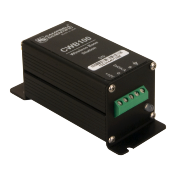
Page 10: Cwb100 Wireless Base Station
Wireless Sensor Network station synchronizes wireless sensor measurements and polls all sensors, storing the collected measurements so that it can transfer them as soon as the datalogger requests them. This minimizes the amount of time the datalogger needs to wait for a response from the network through the CWB100 base station. -
Page 11: Cws220 Wireless Infrared Radiometer
Wireless Sensor Network 1.3 CWS220 Wireless Infrared Radiometer The CWS220 is a Wireless Infrared Radiometer that incorporates Apogee Instrument's SI-111 infrared sensor to provide a non-contact means of measuring the surface temperature of an object. It senses the infrared radiation being emitted by the target. -
Page 12: Cws655 Wireless Water Content Reflectometer
Wireless Sensor Network 1.4 CWS655 Wireless Water Content Reflectometer The CWS655 is based on Campbell Scientific’s CS655 water content reflectometer. It measures volumetric soil water content, electrical conductivity (EC), dielectric permittivity, and ambient temperature of soils or other porous media. -
Page 13: Cws900 Wireless Sensor Interface
Wireless Sensor Network The CWS655 outputs 8 values: Volumetric water content, Bulk electrical conductivity, Dielectric permittivity, Soil temperature, Period Average, Voltage ratio, Internal temperature, Battery voltage, and Signal strength. Additional detail regarding CWS655 output is available in Appendix B. For specifications of the CWS655, see Section 2.4. 1.5 CWS900 Wireless Sensor Interface The CWS900 is a Wireless Sensor Interface. - Page 14 Wireless Sensor Network TABLE 1.5-1. CWS900 Configurations and Outputs Configuration Single Ended Channel 1 Measurement Single Ended Channel 1 and 2 Measurement Single Ended Channel 1, 2, and 3 Measurement Differential Channel Measurement Switch Closure Pulse Count Low Level AC Rain Gage Pyranometer (or Quantum Sensor) 109 Temperature Probe...
- Page 15 Wireless Sensor Network TABLE 1.5-2. CWS900 Wind Sensor Configurations and Outputs Configuration 05103, 05103-45, or 05106 RM Young Wind Monitor 05305 RM Young Wind Monitor 03002 RM Young Wind Sentry Set 034B Met One Windset #40C or #200P NRG Wind Set Additional detail regarding CWS900 configurations and outputs is available in Appendix B.
-
Page 16: Specifications
Wireless Sensor Network 2. Specifications 2.1 Wireless Sensor Network Radio The CWB100 and CWS sensors use a 25 mW FHSS radio. Three models are available depending on location of usage. Table 2.1-1 shows model numbers and locations used for all models. 2.1.1 Electrical TABLE 2.1-1. -
Page 17: Typical Rf Range
Wireless Sensor Network 2.1.2 Typical RF Range RF range is affected by antenna height and by obstacles between the two antennae. The following ranges represent typical distances of RF range as measured with a 0 dBd Omnidirectional 1/2 wave whip antenna connected to the CWB100 radio base station: Base Sensor... -
Page 18: Antenna Options
RG8 cable. A surge suppressor kit, part number 14462, is required for connecting the COAXNTN-L cable to the CWB100. For antenna options for the CWB100E 868 MHz Wireless Base Station, contact Campbell Scientific. 2.2 CWB100 Specifications 2.2.1 CWB100 Physical Specifications Dimensions (including mounting bracket): 10.8 cm x 4.4 cm x 4.4 cm... -
Page 19: Cwb100 Environmental Specifications
Store and use in non-condensing (desiccated) environment. 2.2.4 Datalogger Compatibility The CWB100 is compatible with Campbell Scientific datalogger models CR800-series, CR1000, and CR3000. These dataloggers use the CRBasic instruction CWB100() to communicate with the CWB100. See Section 5 for programming details. -
Page 20: Cws220 Electrical Specifications
Wireless Sensor Network 2.3.2 CWS220 Electrical Specifications Power: 2 AA Batteries 300 μA with 15 minute polling Average Current Drain: Radio: Internal 25 mW FHSS Radio Absolute Accuracy: ±0.2°C @ -10° to +65°C; ±0.5°C @ -40° to +70°C Repeatability: ±0.05°C @ -10° to +65°C; ±0.1°C @ -40° to +70°C Response Time: <1 s to changes in target temperature Wavelength Range:... -
Page 21: Cws655 Environmental Specifications
Wireless Sensor Network 2.4.3 CWS655 Environmental Specifications Temperature Range: -25° to +50°C (-13° F to + 122°F) Humidity Range: 0 to 100% Weather Resistance: IP67 rating for sensor and battery pack (battery pack must be properly installed; each sensor is leak tested) 2.5 CWS900 Specifications 2.5.1 CWS900 Physical Specifications Dimensions:... -
Page 22: Cws900 Environmental Specifications
Wireless Sensor Network 2.5.3 CWS900 Environmental Specifications Temperature Range: -25° to +50°C (-13°F to + 122°F) Humidity Range: 0 to 100% Weather Resistance: IP67 rating for sensor and battery back (battery pack must be properly installed; each sensor is leak tested) 3. -
Page 23: Required Cables
Wireless Sensor Network FIGURE 3.1-1. A205 CWS to PC Interface FIGURE 3.1-2. Connection of A205 3.1.2 Required Cables A data cable, CSI part number 17648, ships with the A205. The cable has a USB type A male connector on one end and a type B male connector on the other end. -
Page 24: Configuration Cd
Wireless Sensor Network 3.1.3 Configuration CD A Configuration CD ships with each CWB100 Wireless Base Station. The CD has software and files needed to configure and use wireless sensors including: • Wireless Sensor Planner • Device Configuration Utility • Device drivers for CWB100 radio •... -
Page 25: Installing Wireless Sensor Planner
Wireless Sensor Network are specified. As the network is being designed, Wireless Sensor Planner automatically determines many individual device settings. After the model is completed, device settings can be written to the devices using Wireless Sensor Planner. Network Planner version 1.1 or higher, available in LoggerNet 4.1 and higher, can also be used to set up a wireless sensor network. -
Page 26: Simple Wsn Example
Wireless Sensor Network 3.2.3.1 Simple WSN Example In this example, a CWB100 base station communicates with a CWS655 and a CWS900 with a 109-L-CWS temperature sensor attached. Both sensors are within radio range of the base so no repeaters are necessary. Although station names and measurement names may be customized in Wireless Sensor Planner, the fastest way to configure the network is to use the default names provided. - Page 27 Wireless Sensor Network Adding Communication Links to Devices The next step is to add links between the base station and the other two devices. This represents the radio communication link between the devices. To create links, click the Link Tool icon on the toolbar. The mouse cursor changes from a hand to a jagged line indicating the Link Tool is currently active.
- Page 28 Wireless Sensor Network To add the link from the CWB100 to the CWS900, select the CWB100 and drag the resulting line to the CWS900. Another Add Link Between Stations dialog box will appear showing the new link. Click the OK button to accept the link.
-
Page 29: Configuring The Devices In The Wsn
Wireless Sensor Network The Radio ID may be left blank and will be filled in automatically when the device is programmed. Use the Measurement Configuration drop-down list to choose the 109 Temperature Probe. The dialog box also shows the default sensor field names that will be used when a measurement is taken. - Page 30 Wireless Sensor Network shown. To save these settings in a XML file for future reference, click Save and choose a filename. To send these settings to the CWB100, click Connect. After settings have been sent to the CWB100, a new window will show which settings have been applied.
-
Page 31: Configuring The Cws655
Wireless Sensor Network 3.3.2 Configuring the CWS655 To configure the CWS655 Water Content Reflectometer, first connect the A205 to the type B USB connector on the 17648 cable. Remove the battery door on the CWS655 and locate the four-pin connector near the top of the sensor. -
Page 32: Configuring The Cws900
Wireless Sensor Network 3.3.3 Configuring the CWS900 To configure the CWS900 Wireless Sensor Interface, first connect the A205 to the type B USB connector on the 17648 cable. Remove the battery door on the CWS900 and locate the four-pin connector near the top of the sensor. Connect the A205 to the sensor at the four-pin connector. -
Page 33: Programming The Datalogger
Wireless Sensor Network transmitted by wireless sensors. See Section 4.2.1 for more information on the format and use of the configuration string. After the configuration settings have been sent to the base station and wireless sensors, the sensor configuration file may be sent to the datalogger. The datalogger must then be programmed to access that file using the third parameter of the CWB100 instruction. - Page 34 Wireless Sensor Network Determining Size of the Array In this example the WSN includes a CWS655 and a CWS900 configured to measure a 109 temperature probe. Section 1.3 shows that the CWS655 transmits 8 values and Section 1.4 shows that the CWS900 transmits 4 values when configured to measure a 109 probe.
-
Page 35: Connecting The Cwb100 To The Datalogger
Wireless Sensor Network Finishing the Program Add a one minute data table and CallTable instruction to complete the program Public WSN(12) DataTable (WSNData,True,-1) DataInterval (0,1,Min,0) Sample (12,WSN(),FP2) EndTable BeginProg Scan (60,Sec,0,0) CWB100(1, WSN(),"CPU:CWSConfig.txt") CallTable WSNData NextScan EndProg Save the program and send it to the datalogger. NOTE If the CRBasic editor does not compile the program and indicates the error message “Undeclared variable CWB100”... -
Page 36: Verify That Data Is Being Transmitted
Wireless Sensor Network Power the CWS sensors by attaching the battery pack to the 4-pin connector. The red LED light will hold steady for about 4 seconds and then turn off. Press and hold the Setup button on the back of the sensor. The blue LED light will flash up to four times indicating the battery voltage then stop flashing. -
Page 37: Connecting Sensors To The Cws900
A DES2 Junction Box with a special –LWS cable may be purchased from Campbell Scientific and the sensor connected to the –LWS cable through a terminal block. The connector pin-out for the CWS900 is shown in Figure 3.9-2. -
Page 38: Cwb100() Instruction
Wireless Sensor Network TABLE 4.1-1. Values Transmitted by CWS Sensors Sensor Values Transmitted CWS220 Wireless Infrared Radiometer CWS655 Wireless Water Content Reflectometer CWS900 Wireless Sensor Interface 4 – 10 See Section 1.4 for more information on number of values transmitted by the CWS900 In the network example shown in Section 3, a CWS655 and a CWS900 configured for a 109-L probe are used. -
Page 39: Configuration String
Wireless Sensor Network Configuration: The Configuration parameter is an optional constant string parameter that specifies a list of sensor descriptions. This configuration string is supplied by the user to predefine sensor and field names along with the order in which values are returned to the destination array. It overrides the names provided by the sensor and predefines field names. -
Page 40: Field Names
Wireless Sensor Network discovered. This can make it difficult to use specific values in the datalogger program because of uncertainty as to which position in the array the value of interest will be assigned. The CRBasic instruction ArrayIndex may be used to reference values returned by wireless sensors regardless of where those values are in the destination array. -
Page 41: Arrayindex() Instruction
Wireless Sensor Network 4.3 ArrayIndex() Instruction The ArrayIndex function is used to return the index of a named element in an array which would otherwise be unknown. The value can then be further processed in the program because of its known position in the array. If the named element is not found, the function returns 0 (this will result in a Variable Out of Bounds error). -
Page 42: Cwb100Rssi() Instruction
Wireless Sensor Network in the array for program use regardless of the order in which the sensor was discovered. CRBasic instruction Fieldnames is used after each output instruction to provide a unique output name to the values. If more than one output instruction is in the DataTable and Fieldnames is omitted, a compiler error will be returned indicating duplicate output names. -
Page 43: Program Example
Wireless Sensor Network Port: The Port parameter is a constant indicating the control port (C1, C3, C5, or C7) to which the CWB100 Data line is connected. Routes: A destination variable of type String where the routing information will be stored. It is important to size the variable large enough to hold all of the routing information. - Page 44 Wireless Sensor Network Example 4.6-1. Program for Wireless Sensor Network Const NumVals = 4 'Values returned by CWS900 Public GetRSSI As Boolean Public WSN(NumVals) Public WNSRoutes As String *100 DataTable(SensorNetwork,True, -1 ) DataInterval( 0,10,Min,0) Average (1,WSN(ArrayIndex("CWS900_Ts")),IEEE4,WSN(ArrayIndex("CWS900_Ts"))= NAN) FieldNames (CWS900_T_C) Average (1,WSN(ArrayIndex("CWS900_Ti")),IEEE4,WSN(ArrayIndex("CWS900_Ti"))= NAN) FieldNames (CWS900_Ti_C) Minimum (1,WSN(ArrayIndex("CWS900_BV")),IEEE4,WSN(ArrayIndex("CWS900_BV"))= NAN,False) FieldNames (CWS900_BattV_Min)
-
Page 45: Cws Button And Led Behavior
Wireless Sensor Network 5. CWS Button and LED Behavior The Setup button on the back of a CWS sensor and the RED and BLUE LED lights provide diagnostic information regarding the sensor and its communication with the CWB100 base station radio. 5.1 Sensor Link to Base Station Press the Setup button momentarily to see how the CWS sensor is linked to the CWB100 base station. -
Page 46: Testing The Network
Wireless Sensor Network 2. If the initial attempt fails to link to the base station, the CWS sensor will delay 5 minutes before attempting to link again. The BLUE LED will be off during this time. The sensor will try to link to the base at a five minute interval a total of three times. - Page 47 Wireless Sensor Network up whenever a measurement is taken and the red LED will light up whenever the measurements are transmitted to the base station. 6. Connect the battery pack to the next wireless sensor, press in the Setup button for 8-10 seconds, and wait for that sensor to pair with the base station radio.
-
Page 48: Maintenance
Wireless Sensor Network Prior to sensor discovery, the numeric monitor will display the name of the public variable specified in the CWB100 instruction with NAN as the output. Once the sensor has been discovered, NAN will change to Undefined. To view the user-specified Field Names in the numeric monitor, delete the original Public variables from the display with the Delete All button and add the Public table again with the Add button. -
Page 49: Replacing A Sensor In The Network
Wireless Sensor Network Distilled water or alcohol works well for most dust/dirt. Salt deposits dissolve better in a weak acid solution (~0.1 molar). Sensors connected to the CWS900 may require regular maintenance and recalibration. See the documentation for the sensor of interest for recommended maintenance and recalibration details. -
Page 50: Troubleshooting
Wireless Sensor Network 8. Troubleshooting Symptom Possible Cause Solution Cannot connect to Wrong serial port Choose correct serial CWB100 with USB number specified port number from drop cable down menu. If correct port number does not display, wait 15 seconds for list to refresh and try again. - Page 51 Wireless Sensor Network Symptom Possible Cause Solution Pressing Setup button Sensor does not have Reconfigure sensor to for 8-10 seconds does radio base station include base station not initiate auto- address programmed radio address discovery (Blue LED into it does not blink every second indicating search for base station) First element in...
- Page 52 Wireless Sensor Network Symptom Possible Cause Solution First element in The measurement This is a rare error destination array names in the datalogger message that should specified in CWB100 do not match the names disappear after the instruction is -3 and all stored in the CWB100 datalogger has made its other elements in the...
-
Page 53: Using Devconfig For Cws Setup
Appendix A. Using DevConfig for CWS Setup CWS Sensors can be configured using Device Configuration Utility, DevConfig, which can be downloaded from www.campbellsci.com/downloads. DevConfig does not allow custom field names and will not generate a configuration string, but it can be used to specify the base station radio address, sensor name, and the measurement configuration for the wireless sensor. - Page 54 Appendix A. Using DevConfig for CWS Setup 5. Once DevConfig connects to the sensor, enter the address of the CWB100 in the field called Base Station Address. If configuring a CWS900, choose the type of measurement the sensor will make from the drop-down menu called Measurement Configuration.
- Page 55 Appendix A. Using DevConfig for CWS Setup 7. If configuring a CWS900 sensor module, you can use DevConfig to ensure that the sensor is correctly configured and connected to the CWS900. To test the sensor, connect the sensor to be measured to the CWS900 and follow the instructions above for establishing communication with DevConfig.
- Page 56 Appendix A. Using DevConfig for CWS Setup...
-
Page 57: Measurement Names And Meanings
Appendix B. Measurement Names and Meanings Default measurement names are shown in Wireless Sensor Planner, Network Planner, and DevConfig software. Custom names may be assigned to the measurements with Wireless Sensor Planner or Network planner. It is good practice to keep the measurement names short. The default names, meanings and measurement units are listed below. -
Page 58: Cws900 Default Names
Appendix B. Measurement Names and Meanings B.3 CWS900 Default Names Default Name Meaning Units Single-ended DC voltage measured Volts, may need additional on pin 5 with respect to pin 3 processing to convert to engineering units Single-ended DC voltage measured Volts, may need additional on pin 6 with respect to pin 3 processing to convert to... - Page 59 Appendix B. Measurement Names and Meanings Default Name Meaning Units Battery voltage of wireless sensor Volts Internal temperature of wireless °C sensor Wind speed average during last meters per second polling interval WSMX Wind speed maximum during last meters per second polling interval.
-
Page 60: Wind Vector Calculations
Appendix B. Measurement Names and Meanings Default Name Meaning Units RWDSD Resultant wind direction standard Degrees deviation. Vector mean wind direction standard deviation calculated over the polling interval with the CSI wind speed weighted algorithm (See B3.1 for details). B.3.1 Wind Vector Calculations When a wind speed sample is 0, the CWS900 uses 0 to process scalar or resultant vector wind speed and standard deviation, but the sample is not used in the computation of wind direction. - Page 61 Appendix B. Measurement Names and Meanings Scalar mean horizontal wind speed, S: S=(Σs where in the case of orthogonal sensors: =(Ue +Un i Unit vector mean wind direction, Θ1: Θ1=Arctan (Ux/Uy) where Ux=(Σsin Θ Uy=(Σcos Θ or, in the case of orthogonal sensors Ux=(Σ(Ue ))/N Uy=(Σ(Un...
- Page 62 Appendix B. Measurement Names and Meanings Standard deviation of wind direction, σ(Θu), using Campbell Scientific algorithm: σ(Θu)=81(1- The algorithm for σ(θu) is developed by noting (Figure B.3-3) that Θ Θ Θ − Θ U / s ; where FIGURE B.3-3. Standard Deviation of Direction The Taylor Series for the Cosine function, truncated after 2 terms is: Θ...
- Page 63 Appendix B. Measurement Names and Meanings ∑ Θ ') / The term, , is 0 if the deviations in speed are not correlated with the deviation in direction. This assumption has been verified in tests on wind data by CSI; the Air Resources Laboratory, NOAA, Idaho Falls, ID;...
- Page 64 Appendix B. Measurement Names and Meanings...
-
Page 65: Battery Life
Appendix C. Battery Life C.1 Battery Characteristics The battery life of the CWS wireless sensors is a function of the polling interval, repeater usage, type of batteries, and temperature. The types of batteries that can be used in the sensors are AA sized alkaline, Lithium, NiMH, or NiCd;... -
Page 66: Rf Connection Type Setting
Appendix C. Battery Life Sensor and Connection 5 Min Polling 10 Min Polling 15 Min Polling CWS900 w/109 15 months 21 months 24 months Probe or CWS655 Same as above, 8 months 12 months 15 months used as a repeater for 1 sensor Same as above, 6 months... -
Page 67: Repair Of A Lost Connection
Appendix C. Battery Life In another situation, there may be a sensor in a location that permits a direct connection to the base, but misses a significant number of data polls. Changing the sensor’s RF Connection Type setting to Connect Through Repeater will force it to go through a repeater, and it will not attempt any direct connection to the base, which may result in fewer missed polls. - Page 68 Appendix C. Battery Life...
- Page 70 Campbell Scientific Companies Campbell Scientific, Inc. (CSI) 815 West 1800 North Logan, Utah 84321 UNITED STATES www.campbellsci.com • info@campbellsci.com Campbell Scientific Africa Pty. Ltd. (CSAf) PO Box 2450 Somerset West 7129 SOUTH AFRICA www.csafrica.co.za • cleroux@csafrica.co.za Campbell Scientific Australia Pty. Ltd. (CSA)
Need help?
Do you have a question about the CWS Series and is the answer not in the manual?
Questions and answers