
Related Manuals for Sartorius WZA N Series


Summary of Contents for Sartorius WZA N Series
- Page 1 Installation Instructions Sartorius Weigh Cells Models WZA...-N, WZA...-NC, WZA224-ND 1000061472...
-
Page 2: Table Of Contents
Control Unit..... . 5 Sartorius equipment. Therefore, be sure AC Power Supply ....6 to check the pin assignments before § These installation instructions describe... -
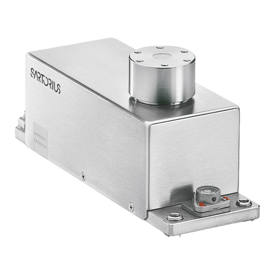
Page 3: General View Of The Equipment
General View of the Equipment Pos. Designation Pos. Designation Electronics module Weigh cell Plate: Interface description Connector (male) for electronics module LED: RxD/Supply voltage (yellow) Threaded hole for equipotential bonding terminal Female connector for the optional display unit Level indicator LED: TxD (red) Threaded hole (M6) for mounting the weigh cell Female connector for weigh cell Data Interface Load receptor DC jack... - Page 4 General View of the Equipment WZA25-NC Pos. Designation Pos. Designation Electronics module Electrical connection Plate: Interface description Positioning holes LED: RxD/Supply voltage (yellow) Mounting surface Female connector for the optional display unit Overpressure inlet 50 mbar, d 6 mm LED: TxD (red) Pressure inlet Cal.-weight circuit mechanism 6 bar, d 3 mm Female connector for weigh cell Load pin Threaded hole for mounting DC jack Overpressure outlet 50 mbar, d 6 mm Data interface Pressure outlet for 10 and 15 Pressure inlet closing mechanism 6 bar, d 3 mm Users should never change any other screws!
-
Page 5: Installation
External calibration – Do not expose the equipment to unnec- The equipment is designed to provide essarily extreme temperatures, moisture, – WZA...-NC: Internal calibration reliable results under normal ambient shocks, blows or vibration. $ It is a good idea to save the box and all conditions. If you have any questions – Equipment installed on the load or difficulties when developing your parts of the packaging until you have receptor can interfere with weigh cell weighing system, please contact the successfully installed your equipment. functions. The user accepts all liability specialists at Sartorius. When designing Only the original packaging provides for production release and the speci- and setting up your weighing system, the best protection for shipment. fications of the entire equipment. The $ Before packing your equipment, please observe the following so that specifications attained by your system you will be able to work with added unplug all connected cables to prevent may differ from those listed in the speed and accuracy: unnecessary damage. "Specifications” Chapter. $ Gravitational acceleration 0 300 m/s – Avoid exposing the equipment to the effects of extremely high temperatures;... -
Page 6: Ac Power Supply
AC Power Supply AC Adapter Assembly Fatal electric shocks can be caused by use of the incorrect power plug adapter or improper use of the power plug adapter. – Attach the country-specific power plug adapter to the AC adapter. The power plug adapter must be suitable for the wall outlet at the installation location. -
Page 7: Connecting The Ac Adapter
§ If the stated supply voltage does not comply with the local supply voltage or there is no suitable AC adapter available: Do not use the AC adapter. Contact Sartorius Service. § Only use original Sartorius AC adapters. § Insert the right-angle plug from the AC adapter into the jack on the electronics module and tighten the fastening screw § Connect the equipment to power:... -
Page 8: Connecting Electronic Peripheral Devices
Connecting Electronic Peripheral Devices § Make absolutely sure to unplug the weigh cell from AC power before you connect or disconnect a peripheral device (e.g., PC) to or from the interface port: Warm-up Time The amount of warm-up time required depends in part on the system used. To return precise results, the weigh cell must warm up for at least the length of time indicated below after it is connected to power for the first time: – WZA224-N/WZA224-ND: 45 minutes – Other WZA...-N/-NC-models: 30 minutes Only after this time will the device have reached the required operating temperature. WZA8202-N/-NC: Installing Parts § Position spacer and load receptor § Tighten the (S1) screw supplied to fasten the load receptor: For torque values, see table on the next page Leveling the Load Receptor and Attaching the User-specific Transducer § Remove (1) screw § Use the (2) screws to radially position and level the load receptor (minor height adjustment also possible) §... -
Page 9: Maximum Permissible Load On Load Receptor
Maximum Permissible Load on Load Receptor: Model Max. torque Screwing torque Max. force opposite Max. forces to direction of load (-F WZA224-N WZA224-ND WZA224-NC 2 Nm 1 Nm 3 N 20 N WZA523-N WZA523-NC 2.5 Nm 1 Nm 6 N 25 N WZA1203-N WZA1203-NC 4 Nm 2 Nm 15 N 40 N WZA8202-N WZA8202-NC 8 Nm 4 Nm 100 N 80 N 200 N WZA25-NC 0.1 Nm 0.5 Nm 2 N Higher loads may result in damage to the weigh cell. -
Page 10: Leveling The Weigh Cell In A Portable Weighing System (Leveling Feet Optional)
Leveling the Weigh Cell in a Portable Weighing System (Leveling Feet Optional) Purpose: – To compensate for uneven areas at the place of installation. – To ensure that the weigh cell is placed in a perfectly horizontal position for consistently reproducible weighing results. – Always level the weigh cell again any time after it has been moved to a different location. § Adjust the leveling feet until the air bubble is centered within the circle on the level i ndicator. Permanently Installed Weigh Cells – Adjust the weigh cell after it has been installed in the system in its permanent location – see next page. The weigh cell must be calibrated/adjusted again any time its location or position is changed. – For optimum operation, install the weigh cell in a horizontal position. 1) Bottom plate of the weigh cell 2) Fastening frame of the system § Fastening with M6 screws: Connection to the threaded fasteners on the weigh cell (1): torque 2.5 Nm § Fastening with M4 screws: Connection to the threaded fasteners of a user-specific frame (2). -
Page 11: Operation
Aside from purely mechanical solutions Magnetizable or magnetized samples (e.g., using a special weighing pan to and the weigh cell itself interact Samples must be applied very carefully, shield the sample), bombarding the with magnetic fields and magnetiz- whether manually (using a forceps) sample with ions of opposing polarity able or magnetized parts in the area or automatically (by a robot or filling to neutralize the surface charge is one surrounding the weighing system. system). of the most effective methods for elim- The system can be shielded from inating static electricity. Sartorius can external magnetic fields to some extent When designing a draft shield device, provide ionization devices for installa- using (soft magnetic) plates. steps must be taken to keep the tion in weighing systems. increase in temperature within the Effects of Drafts weighing chamber to a minimum The area around the weigh cell, like Depending on the size of the load (e.g., using a bypass). plastic parts, can also contain charges receptor and the sample, the effects of drafts may occur. that negatively affect the accuracy of weighing results. Appropriate steps To minimize this effect, install a draft (grounding) taken in the design of a shield for protection. -
Page 12: Below-Cell Weighing
Below-Cell Weighing A port for a below-cell weighing hanger is located on the bottom of the weigh cell (not on model WZA25-NC). § Remove the closing screw. $ Overload protection – S tandard feature on the following models: WZA224-N/-NC, WZA1203-N/-NC, WZA523-N/-NC No overload protection provided on the following models: WZA8202-N/-NC, WZA25-NC § Carefully install the customer-specific hook. Threaded fastener for hook: M3 Maximum torque: 0.8 Nm. Maximum screw installation depth: do not exceed 5 mm! $ Install a draft shield if necessary... -
Page 13: Operation With The Optional Yac01Ed Display And Control Unit
Operation with the Optional YAC01ED Display and Control Unit Connect display and control supplied to the weigh cell electronic unit using cable. Connecting cable: Approx. 1 meter long with 15-pin D-Sub plug and socket. Pin 15 is not assigned. Overview of Display and Operating Elements Position Designation Position Designation 1 Weight units Clear Function Menu level indicator T his key is generally used to Tare | Zero cancel functions: S ymbol “GLP printing mode – Q uit application program active” – C ancel calibration/adjustment Symbol: “Printing mode active” routine | Exit menu Application program active Start the calibration process... -
Page 14: Basic Weighing Function
Basic Weighing Function Features – Taring the weigh cell – Print weight value Preparation § Switch on the weigh cell: Press the e key § Tare the balance/scale, if necessary: Press w $ If necessary, change the configuration settings: see the chapter entitled “Configuration” $ If desired, load the factory settings: see the chapter entitled “Configuration” Additional Functions: $ Switching off the weigh cell: Press e Example: Determine a weight value Step Press key Display/Printout 1. Switch on the weigh cell: 0.0 g Self-test runs followed by automatic initial tare function. + 2. Place container on weighing pan 11.5 g (in this example 11.5 g). -
Page 15: Configuration (Operating Menu)
One menu level higher (left cursor) 3. Input 4. Information Indicates menu level 5. Language setting Factory Settings for the Parameters The factory-set configurations are i dentified by an “o” in the list below. Customer-specific settings can be configured on request. Preparation $ Using the CAS-Suite configuration soft- ware from Sartorius installed on a PC, you can process the operating menu parameters as follows: – Read – Edit – Print – Save or Using the optional YAC01ED control unit... - Page 16 Menu Navigation Example: Setting the language Step Press key Display 1. O pen the menu: hold Applic. In weighing mode: first menu item is shown 2. S croll upward within the Repeatedly press Input menu level; After the last menu code, languag. the first code is displayed again (scroll) 3. Select next menu level Repeatedly press English (scrolls to the right) 5. C hange setting: German Select the menu item by scrolling up 6. C onfirm setting:; German “o” indicates the active Menu item...
-
Page 17: Menu Structure (Overview)
Menu Structure (Overview) Level 1 Level 2 Level 3 Codes 1. 1. 1. Setup Bal.Scal. Ambient Ambient conditions (Adapt filter) (Weigh cell functions) 1. 1. 2. App.Filt. Application filter 1. 1. 3. Stab.Rng. Stability range 1. 1. 4. St.Del. Stability delay Taring Taring 1. 1. 5 1. 1. 6 AutoZer. Auto zero 1. 1. 7. Wt.Unit Basic weight unit 1. 1. 8. Display Display accuracy 1. 1. 9. Cal./adj. Function of the Q key 1. 1.10. Cal.routine 1. 1.11. Cal.Unit Weight unit for calibration 1. 1.12. Zero RNG. Zero range 1. 1.13. Zero.on Zero at Power On 1. 1.14. -
Page 18: Parameter Settings: Overview
Parameter Settings: Overview ο = Factory setting; √ = User-defined setting Level 1 Level 2 Level 3 Level 4 Code 1.) Setup 1. 1. 1. 1 Bal.Scal Ambient V.Stable Very stable conditions Weigh cell conditions 1. 1. 1. 2 ο Stable Stable conditions functions (Filter adaptation) 1. 1. 1. 3 Unstabl Stable conditions 1. 1. 1. 4 V.Unstbl. Very unstable conditions 1. 1. 2. 1 ο Final.Rd. Final readout mode App.Filt. Application filter 1. 1. 2. 2 Filling Filling mode 1. 1. 3. 1 Stab.Rng. 1/4 dig. (digit) Stability range 1. 1. 3. 2 1/2 dig. (digit) 1. 1. 3. 3 1 dig. (digit) 1. 1. 3. 4 ο ... - Page 19 Level 1 Level 2 Level 3 Level 4 Code 1. 5. 1. 3 Setup Interf. Baudrate 600 Interface 1. 5. 1. 4 ο 1200 1. 5. 1. 5 2400 1. 5. 1. 6 4800 1. 5. 1. 7 9600 1. 5. 1. 8 19200 1. 5. 1. 9 ο 38400 (factory-set on WZA224-ND) 1. 5. 2. 3 ο Odd Parity Parity 1. 5. 2. 4 Even 1. 5. 2. 5 None 1. 5. 3. 1 ο 1 Stop stop bit Number of stop bits 1. 5. 3. 2 2 stop 1. 5. 4. 1...
- Page 20 Level 1 Level 2 Level 3 Level 4 Code 1. 6. 5. 1 ο off Setup dat.rec. Prt.Init. (Printout) Printing appli- 1. 6. 5. 2 all All parameters cation parameters 1. 6. 5. 3 mainpar. Main parameters 1. 6. 6. 1 ο 16. char. 16 characters (w/o ID) Format Line format for 1. 6. 6. 2 22. char. 22 characters (w/ ID) printout 1. 6. 6. 3 2nd line with date/time 1. 6. 7. 1 ο off GLP ISO/GLP- compliant 1. 6. 7. 2 Cal.-adj. Only for calib./adj. printout 1. 6. 7. 3 Always on 1. 6. 8. 1 ο 24 h 24-hour format time 1. 6. 8. 2 12 h 12-hour format “AM/PM”...
- Page 21 2. 7. 2. 1 start manual 2. 7. 2. 2 ο auto. Automatic 2. 8. 1. 1 ο Mul. Multiplier Calc. Method Calculation (operator) 2. 8. 1. 2 div. Divisor 2. 8. 2. 1 Dec.Plcs none No dec. places Decimal places 2. 8. 2. 2 ο 1 dec.pl. 1 decimal place 2. 8. 2. 3 2 Dec.Pl. 2 decimal places 2. 8. 2. 4 3 Dec.Pl. 3 decimal places 2. 9. 1. 1 Density dec.plcs none No dec. places determination Decimal places 2. 9. 1. 2 ο 1 dec.pl. 1 decimal place ) I f you need more detailed information on application programs: Please contact your local Sartorius dealer.
- Page 22 Configuration Operation (Setup) Purpose Output Format with 16 Characters (Compatibility with Current Weigh Cells) The weigh cells are equipped with an interface port for connection to a Display segments that are not activated are output as spaces. computer or other peripheral device. The type of character that can be output depends on the character’s position: You can connect a computer to change, Position 1 9 10 11 12 13 14 15 16 start and/or monitor functions and E CR LF application programs. – Features Type of interface: Serial interface Interface operating mode: Full duplex Spaces CR: Carriage return Level: RS-232...
- Page 23 Example: Output of the weight value + 123.56 g Position Position 1: Plus or minus sign or space Position 2: Spaces Position 3 - 10: W eight value with decimal point, leading zeros are output as spaces. Position 11: Spaces Position 12–14: Characters for unit of measure or space Position 15: Carriage return Position 16: Line feed Output Format with 22 Characters (Compatibility with Current Weigh Cells) When data is output with an ID code, the 6-character code precedes the 16-character string described above. These six characters identify the subsequent value. 10 11 12 13 14 15 16 17 18 – ID code character Unit symbol Spaces...
- Page 24 Commands (Data Input Format Compatible with Current Weigh Cells) The computer connected via the data port can send commands to the weigh cell for controlling functions. The commands sent are control commands and may have different formats. Control commands consist of up to 13 characters. Each character must be transmitted according to the settings configured in the operating menu for data transmission. Formats for Control Commands Format 1: Esc Format 2: Esc Esc: Escape (optional) CR: Carriage return Command character LF: Line feed (optional) Underline Command character Format 1: ! Meaning K Ambient conditions: Very stable L Ambient conditions: calm M Ambient conditions: unstable N Ambient conditions: Very unstable O Block keys P r key (print, auto print; activate or block) Q Acoustic signal R Unblock keys S Restart/self-test...
- Page 25 Example: “Calibration/Adjustment” Function via RS-232 Interface Purpose Calibration is the determination of any difference between the measured value displayed and the true weight (mass) of a sample. Adjustment is the correction of this difference, or its reduction to a suitable level within maximum permissible error limits. Characteristics The adjustment procedure should only be started when – The weigh cell is not loaded – The weigh cell is tared – The weighing signal is stable – The sensitivity of the balance can be corrected by max. 2%. If these criteria are not met, error message “Err 02” appears. Error message “Err02”: – Note ambient conditions – Weigh cell needs stability – I f necessary, change the pre-configured balance parameters: Select Ambient conditions menu item 1.1.1.4 (very unstable) or execute interface command ESC N Adjustment can be made using different weight units: CAL.Unit > Gram, Kilogr.
- Page 26 Internal Calibration/Adjustment External Calibration Default setting: Default setting: SETUP - BAL.SCAL.- CAL.Just. - Cal.Int. SETUP - BAL.SCAL.- CAL.Just. - Cal.Ext. The required calibration weight is configured at the factory Voraussetzung: (see “Specifications”). The weigh cell housing has a built-in motorized calibration/ adjustment weight. Step Execute interface Display/ command Output § Select calibration: Command ESC Z 1. Tare balance ESC T 0.0000 g > T he internal calibration weight is automatically loaded > The balance is calibrated 2. Start adjustment routine ESC W CAL.ext. > W hen the setup is configured to “Calibration and adjustment in one,” the balance will be adjusted automatically O nce you store the zero > T he internal calibration weight is removed point, a prompt for the - 50.0000 g...
-
Page 27: Data Interface Port: Compatibility With Older Weigh Cells (Previous Models)
Data Interface Port: Compatibility with Older Weigh Cells (Previous Models) Once command »ESC s9_« has been Data Output Format with 16 Characters sent, data input and data output behave as in the earlier Sartorius WZ-/ Characters that are displayed blank are printed as spaces. Display values without a decimal WZA weigh cells (previous models). point are output without a decimal point. Data Output Format The type of character that can be output depends on the character’s position: In operating mode »SBI«, 16 characters are printed out. Normal Operation Example: Position 1 9 10 11 12 13 14 15 16 253 pcs A A E CR LF –... - Page 28 Special Codes Position 1 9 10 11 12 13 14 15 16 – – * CR LF H H Space – –: Final readout Overload H H: O verload in checkweighing (Function is only available during operation with following peripheral devices: Optional display unit or software YAD01IS) Underweight L L: Underweight in checkweighing Adjustment Error Messages Position 1 9 10 11 12 13 14 15 16 # # # * CR LF Space...
- Page 29 No errors are generated just because ating menu settings for Ambient(ambient no peripheral device is connected to an conditions) (menu code 1. 1. 1. x) and Aut. interface port (open data port). cycl. (time-dependent autom. printing; menu code 1. 6. 3. x). Handshake If you activate the auto print setting, The weigh cell interface (Sartorius data will be transmitted immediately the Balance Interface = SBI) moment you turn on the balance/scale. has transmit and receive buffers. In the operating menu, you can define You can define the different handshake whether automatic printing can be stopped parameters in the Setup menu of your by pressing the “Print” key or using the weigh cell: interface. – Hardware handshake (CTS/DTR) – Software handshake (XON, XOFF) – No handshake Hardware handshake With a 4-wire interface, 1 more c haracter can be transmitted after CTS (Clear to Send).
-
Page 30: Pin Assignment Chart
Pin Assignment Chart Female Interface Connector: 25-contact D-Submini (DB25S) with screw lock hardware Required Male Connector (Recommendation): 25-contact D-Submini (DB25S) with integrated shielded cable clamp assembly (Amp 826 985-1C) and fastening screws (Amp 164 868-1) Warning When Using Pre-wired RS-232 Connecting Cables: The pin assignments in RS-232 cables purchased from other manufacturers may be incompatible with Sartorius weighing instruments. Be sure to check the pin assignments against the chart below before connecting the cable, and disconnect any lines identified differently from those specified by Sartorius (e.g., pin 6). Failure to do so may cause malfunction, damage or even completely ruin your balance/scale and/or peripheral device(s). Pin Assignments: Pin 1: Signal Ground Pin 2: Data Output (TxD) Pin 3: Data Input (RxD) Pin 4: Internal Ground (GND) Pin 5: Clear to Send (CTS) Pin 6: Not Connected Pin 7: Internal Ground (GND) -
Page 31: Cabling Diagram
Cabling Diagram For connecting a computer or other peripheral device to the balance/scale using the RS-232C/V24 protocol and cable lengths of up to 15 m (approx. 50 ft). Do not connect any other pins to the cable connector of the balance/scale! Waage Buchse 25-pin Computer Stecker 9 pin TxD 2 RxD 3 CTS 5 DTR 20 GND 4/7 GND 14 Waage Buchse 25-pin Computer Stecker 25 pin TxD 2... -
Page 32: Troubleshooting Guide
Use service tool and built-in „Close“ function. err 30 TC converter failure Contact Sartorius Service. err 50 or 53 Checksum error Contact Sartorius Service. err 241 Checksum error Carry out menu reset. err 243 Checksum error Calibrate | adjust balance | scale. err 245 or 247 Checksum error Contact Sartorius Service. err 249 Weight readout changes constantly Unstable ambient conditions Change setup location. (excessive vibration or draft) Adjust Setup configuration. Foreign object is caught between Remove foreign object. weighing pan and housing The weight readout is obviously wrong Balance | scale not calibrated | adjusted Adjust Balance was not tared before weighing Tare * = can only occur during operation via the SBI interface (ESC f3_/f4) If any other errors occur, contact Sartorius Service. For contact information: go to: http://www.sartorius.com... -
Page 33: Shipping | Disposal
Sartorius shall be charged to sender. § Decommission the device. § Contact Sartorius Service for instructions on how to return devices or parts (please refer to www.sartorius.com). § Pack the device and its parts properly for return. -
Page 34: Technical Data
/ mA (max.) / W (max.) 15 ± 5% / 330 / 5 Installation location, above sea level (NN) 3000 Protection class according to EN/IEC 60950-1 Protection class according IP40 to EN/IEC 60529 ) = depends on system design ) = f or operation with greater preload setting, please send e-mail to request YAD018S configuration software; e-mail address: fast.factory@sartorius.com Greater preloads are possible, but reduce the weighing capacity. ) = T he weighing time is the time period in which the measured value oscillates within the stated range of the static end value. Test weight approx. 25% of max. -
Page 35: Dimensions (Scale Drawings)
Dimensions (Scale Drawings) Electronics module: Optional YAC01ED Display and Control Unit: All dimensions are given in millimeters... - Page 36 Sartorius-Elektronikbox Base plate: AISI 304 Cable length: 3 m Haube: 15-pin D-Sub male connector Housing cover: AISI 304 for Sartorius electronic PCB box Lastflansch: Load flange: AISI 304 Libelle: Aluminium (blank) Level indicator: Aluminium (without finish) Schutzklasse der Zelle: IP44...
- Page 37 Aufnahme von Anbauteilen zur Sartorius-Elektronikbox for holding add-on components Cable length: 3 m 15-pin D-Sub male connector for Sartorius electronic PCB box 3 Gewindestifte zur Ausrichtung des Lastflansches 3 headless screws for aligning Werkstoffe / Materials: the load flange...
- Page 38 Base plate / Housing cover: AISI 316 L Cable length: 3 m Aufnahmezapfen: Titan 15-pin D-Sub male connector Pan pin: Titanium for Sartorius electronic PCB box Ø 6 H8; 6 deep M6; 6 deep mounting surface glue free area (172x17) 6 H8; 6 deep 12.5 -0.01...
- Page 39 Kabellänge: 3 m 15-pol. D -Sub-Stecker zur Sartorius-Elektronikbox 96.55 ±0.5 Cable length: 3 m 15-pin D-Sub male connector for Sartorius electronic PCB box ; 7 tief/deep Werkstoffe / Materials: zur Aufnahme von Anbauteilen Grundplatte: 1.4404 for holding add-on components Base plate:...
- Page 40 Sartorius-Elektronikbox Base plate: AISI 304 Cable length: 3 m Haube: 15-pin D-Sub male connector Housing cover: AISI 304 for Sartorius electronic PCB box Lastflansch: Load flange: AISI 304 Libelle: Aluminium (blank) Level indicator: Aluminium (without finish) Schutzklasse der Zelle: IP44...
-
Page 41: Accessories
Accessories Product Order No. Display and control unit with cable (0.9 m) for connection to enclosed electronics module YAC01ED Second display for connection to data interface YRD03Z Configuration software for settings, calibration/adjustment and setting the preload Sartorius CAS-Suite SartoConnect data transfer software (for loading weight values in a PC running Windows ® 95/98/NT and direct processing with application programs such as Excel, Access, etc.) incl. adapter cable (1.5 m) from weigh cell to PC (12-pin to 9-pin) YSC01I Data cables RS-232 – for PC connection, 25-pin (m) / USB type A, length approx. 1.8 m YCC01-USBM2 – for PC connection, 25-pin (m) / 9-pin (f), length approx. 2.0 m 7357314 AC adapter YEPS01-15VOH IP40 protection in accordance with VDE* 0470/529 Additional options and accessories available on request * VDE = Verband der Elektrotechnik, Elektronik, Informationstechnik (Association for Electrical, Electronic & Information Technologies) -
Page 43: Fcc Supplier's Declaration Of Conformity
Connections between the device and peripherals must be made using shielded cables in order to maintain compliance with FCC radio frequency emission limits. Any modifications made to this device that are not approved by Sartorius may void the authority granted to the user by the FCC to operate this equipment. -
Page 44: Csa Certificate Of Compliance
CSA Certificate of Compliance... - Page 46 Sartorius Lab Instruments GmbH & Co. KG Otto-Brenner-Strasse 20 37079 Goettingen, Germany Phone: +49.551.308.0 www.sartorius.com The information and figures contained in these instructions correspond to the version date specified below. Sartorius reserves the right to make changes to the technology, features, specifications and design of the equipment without notice.
Need help?
Do you have a question about the WZA N Series and is the answer not in the manual?
Questions and answers