Furuno NX-700B Operator's Manual
Navtex receiver
Hide thumbs
Also See for NX-700B:
- Service manual (142 pages) ,
- Specifications (2 pages) ,
- Operator's manual (89 pages)
Table of Contents
Advertisement
Advertisement
Table of Contents
Troubleshooting

Related Manuals for Furuno NX-700B


Summary of Contents for Furuno NX-700B
- Page 1 NAVTEX RECEIVER NX-700A/B...
- Page 2 Pub. No. OME-56490 ( ( HIMA HIMA ) ) NX-700A/B NX-700A/B The paper used in this manual is elemental chlorine free. FURUNO Authorized Distributor/Dealer FURUNO Authorized Distributor/Dealer FIRST EDITION : FIRST EDITION : MAY. MAY. 2005 2005 : : JUN.
-
Page 3: Important Notice
• This manual is intended for use by native speakers of English. • FURUNO will assume no responsibility for the damage caused by improper use or modification of the equipment or claims of loss of profit by a third party. - Page 4 Immediately turn off the power at the switchboard if the equipment is emitting smoke or fire. Continued use of the equipment can cause fire or electrical shock. Contact a FURUNO agent for service. Keep heater away from equipment. A heater can melt the equipment's power cord, which can cause fire or electrical shock.
- Page 5 Observe the following compass safe distances to prevent deviation of a magnetic compass. Standard Steering NX-700A Display unit NX-700B Receiver unit NX-7001 Attach securely protective earth to the ship's body. The protective earth is required to the power supply to prevent electrical shock.
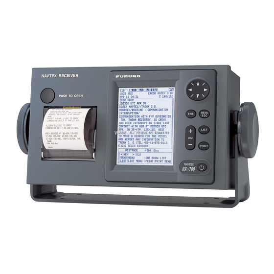
- Page 6 Our extensive global network of agents and dealers furthers this dedication to excellence. The NX-700A/B is just one of the many Furuno developments in the field of marine radio communication. NX-700A: Display unit w/printer...
- Page 7 Meteorological warnings, Search and Rescue (SAR) information and other navigational information for NAVTEX receiver-equipped vessels sailing in coastal waters. The FURUNO NX-700 NAVTEX receiver receives NAVTEX messages and automatically displays them together with station ID and message category information.
-
Page 8: Table Of Contents
3.5 Restoring All Default Settings ... 3-6 4. INSTALLATION ... 4-1 4.1 Display Unit ... 4-1 4.2 Receiver Unit... 4-3 4.3 Antenna Unit ... 4-4 4.4 Printer (NX-700B only) ... 4-5 4.5 Wiring... 4-5 4.6 Setting of Printer... 4-10 4.7 Digital Interfacing...4-11... - Page 9 MENU TREE... AP-1 SPECIFICATIONS ... SP-1 PACKING LISTS ... A-1 OUTLINE DRAWINGS ... D-1 INTERCONNECTION DIAGRAM...S-1...
-
Page 10: Equipment Lists
EQUIPMENT LISTS Standard Supply Name NX-700A Display Unit NX-700B Receiver Unit NX-7001 Antenna Unit NX-7H CP08-01810 CP08-01820 CP08-01870 CP08-01880 CP08-01890 Installation CP08-01860 Materials CP08-01863* CP08-01864* CP08-01861* Spare Parts SP08-02101* Accessories FP08-00800* Type Code No. 000-040-180 000-040-210 000-040-350 000-040-362 000-040-363 000-040-349... - Page 11 000-152-699 000-152-700 000-152-701 000-803-239 000-803-240 000-806-114 004-365-780 Remarks 1 set For NX-700A For NX-700A For NX-700B 10 m, w/connector 20 m, w/connector 30 m, w/connector 40 m, w/connector 50 m, w/connector 10 m 20 m 30 m 40 m 50 m...
-
Page 12: System Configurations
To be installed in an exposed area Display unit To be installed in a protected area Receiver unit DISPLAY UNIT NX-700A Max. 15 m NX-7001 ANTENNA UNIT NX-7H Max. 100 m External Alarm Printer (NX-700B only) (Integrated Navigation System) Navigator... -
Page 13: Principle Of Navtex System
PRINCIPLE OF NAVTEX SYSTEM How NAVTEX Works NAVTEX is an acronym meaning Navigational Telex, and as its name shows, it is a kind of narrow band radio teletype system for sending (by frequency shift keying) text messages expressed in a 7-unit code. The difference is that a NAVTEX transmitter transmits nine control characters (header code) ahead of the main message, so that the receiver can identify the station, message type and serial number automatically. -
Page 14: Message Format
1. PRINCIPLE OF NAVTEX SYSTEM Message Format For automatic identification of messages, each message starts with nine control characters, called “Header codes”. The first five characters are always “ZCZC_“ and common to all messages. This part is used for message synchronization. The latter four characters are designed as B1, B2, B3 and B4 indicate origin, category and serial number of the message. -
Page 15: Navtex Station Map
1. PRINCIPLE OF NAVTEX SYSTEM NAVTEX Station Map... -
Page 16: Navtex Station List
1. PRINCIPLE OF NAVTEX SYSTEM NAVTEX Station List Station Country area Belgium Oostende Estonia Tallinn Iceland Reykjavik Radio Ireland Valentia Malin Head France Niton Netherlands Den Helder Norway Bodo Radio Rogaland Radio Vardoe Radio Svalbard Orlandet Sweden Bjuroklubb Gislovshammar Grimeton United Cullercoats Kingdom... - Page 17 Station Country area Bulgaria Varna Croatia Split radio Cyprus Cypradio Egypt Alexandria Serapeum France Toulon Greece Iraklion Kerkyra Limnos Israel Haifa Italy Roma Augusta Cagliari Trieste Malta Malta Russian Novorossiysk Federation Spain Cabo de la Nao Turkey Istanbul Samsun Antalya Izmir Ukraine Mariupol...
- Page 18 1. PRINCIPLE OF NAVTEX SYSTEM Station Country area Canada Labrador Iqaluit, NU United States Miami Boston New Orleans Portsmouth Isabella Savannah, GA Netherlands Curacao Antilles Argentina Ushaia Rio Gallegos Comodoro Rivadavia Bahia Blanca Mar del Plata Buenos Aires Uruguay La Paloma Namibia Walvis Bay South Africa...
- Page 19 Station Country area Saudi Arabia Jeddah Oman Muscat Pakistan Karachi China Sanya Guangzhou Fuzhou Shanghai Dalian Indonesia Jayapura Ambon Makassar Jakarta Japan Otaru Kushiro Yokohama Moji Naha Korea, Chukpyong Republic of Pyongsan Malaysia Penang Miri Sandakan Singapore Singapore Thailand Bangkok Radio United States Guam 1.
- Page 20 1. PRINCIPLE OF NAVTEX SYSTEM Station Country area Vietnam Ho Chi Minh City Haiphong Danang Taiwan Kaohsiung Associate Hong Kong Member of IMO Canada Prince Rupert Tofino United States San Francisco Kodiak Honolulu Cambria Astoria Russian XIII Kholmsk Federation Murmansk Arkhangelsk Astrakhan Chile...
-
Page 21: Operation
Adjusts the panel and LCD dimmer. +: Raises the setting. - : Decreases the setting. Display unit, front view DUAL CHANNEL NAVTEX NX-700 FURUNO ELECTRIC CO., LTD. ROM : OK RAM : OK XX: Program version No. Program No. 0850193-XX... -
Page 22: Adjusting Lcd Dimmer
2. OPERATION At the default setting, the equipment functions as below; When the results of the check are OK, ALL MESSAGE display for 518 kHz appears. This screen shows all messages received in 518 kHz. You can switch 518 kHz (International message) and 490 kHz (local message) to display. -
Page 23: Confirming The New Message
Confirming the New Message When you receive a new message, do one of the following depending on message received. SAR (Search and Rescue) message 1. When an SAR message is received, the audible alert sounds and details for the SAR message appear. 2. -
Page 24: Sample Messages
2. OPERATION Sample Messages Press ▲ or ▼ on the cursor pad to choose a message, and then press the ENT key to show the detailed information for that message. The message list and detailed message displays can be switched by pressing the ENT key. Frequency (paragraph 2.9) Status icon (paragraph 2.14) Category of messages... -
Page 25: Choosing The Receive Mode
Choosing the Receive Mode The NAVTEX menu allows you to select what station to receive, automatically, manually. The Auto mode requires navigation data, and stations are automatically selected according to the distance between own ship and NAVTEX stations. If navigation data is not input, all stations are selected. The manual mode lets you freely stations to receive. -
Page 26: Choosing The Local Frequency
2. OPERATION Choosing the Local Frequency You can choose 490 kHz or 4209.5 kHz as the local frequency. This function is only available for the Auto and Manual modes. (See paragraph 2.6.) 1. Press the MENU/ESC key to show the main menu. 2. - Page 27 3. Press ▲ or ▼ to choose “Rcv Station & Msg” or “User Select Station & Msg”. 4. Press the ENT key to open the appropriate editing window. (Below is the Rcv Station & Msg editing window.) Internaitional frequency Station Message Local frequency* Changeable item...
-
Page 28: Switching The Frequency To Display
2. OPERATION Switching the Frequency to Display With showing the message list, you can switch the frequency to 518 kHz or 490 (or 4209.5) kHz by pressing ◄ or ► key. 2.10 Alarm Messages The sequence of events when an alarm message is received is as shown below. When receiving SAR (Search and Rescue) message: The audible alarm beep sounds, and the SAR message is shown. -
Page 29: Processing Messages
2.11 Processing Messages Choosing messages to display You can choose which category of messages to display: All, Alarm, User Selected and Good messages. 1. With the message list or detailed message shown, press the LIST key to show the list options. 2. -
Page 30: Printing Messages
2.12 Printing Messages Received messages can be printed automatically or manually, from the built-in printer (NX-700A) or external printer (NX-700B). Printing all messages displayed All messages chosen on paragraph 2.11 can be printed out. 1. Press the PRINT key with showing all messages. - Page 31 Printing each message Press ▲ or ▼ to choose the desired message from the list. Press the ENT key to show the detailed information. Press the PRINT key. Press ▲or ▼ to choose “Print” from the window. Press the ENT key to print. Printing messages automatically When receiving a message, it can be printed out immediately.
-
Page 32: Editing The Navtex Station List
2. OPERATION 2.13 Editing the NAVTEX Station List Maximum 300 NAVTEX stations can be registered into the memory. Note: To cancel editing of a NAVTEX station, press the MENU/ESC key. The message “Exit without saving?” appears. Choose “Yes”, and then press ENT key. - Page 33 NAV Area Station Name Latitude Longitude Station ID Sertvice Area 5. Confirm that NavArea is chosen, and then press the ENT key to show the area No. window. 6. Press ▲ or ▼ to choose a Nav area No. (1 to 16, and EXT), and then press the ENT key.
- Page 34 2. OPERATION Editing NAVTEX station Existing NAVTEX station may be edited as follows: 1. Press the MENU/ESC key to show the main menu. 2. Press ▲ or ▼ to choose Service, and then press the ENT key. 3. Press ▲ or ▼ to choose Edit Station List, and then press the ENT key. 4.
-
Page 35: Icons
7. Press ▲ or ▼ to choose Delete, and then press the ENT key. The message “Delete station?” appears. 8. Press ◄ to choose “Yes”, and then press the ENT key to close the edit window. 9. Press the MENU/ESC key several times to close the menu. 2.14 Icons The NX-700 shows various icons to denote equipment status, and these are as... -
Page 36: Messages List
2. OPERATION 2.15 Messages List In addition to the message “Received new local (int’l) msg.” the following message-related messages may appear on the display. Message New message received. Oldest message deleted to free up memory. Same message with lower error rate received. Currently displayed message will be deleted. -
Page 37: Other Functions
2.16 Other Functions This paragraph describes the various options which allow you to set up your unit to suit your needs. NAVTEX menu Item Description Receive Chooses the receiving mode. (See Mode paragraph 2.6.) Local Chooses the local channel. Channel Auto Print Chooses the message to print automatically. - Page 38 2. OPERATION Display menu Item Selects the speed of scrolling by pressing ▲ or ▼. Slow: Scrolls by one line. Fast: Scrolls by half of screen. Scrolling Skips to $$: Scrolls line by line in list display; Skips to $$ position in detailed display.
- Page 39 Service menu Item Selects the data transmission speed at which to input data Input from INS. Speed Output Selects the data transmission speed to output data to the INS. Speed Turns the header (Own ship’s position, date, frequency, error rate and distance information when receiving a message) for printing on/off.
- Page 40 2. OPERATION This page is intentionally left be blank. 2-20...
-
Page 41: Maintenance & Troubleshooting
MAINTENANCE & TROUBLESHOOTING This chapter provides information necessary for keeping your unit in good working order and remedying simple problems. Maintenance Regular maintenance is important for optimum performance. A maintenance program should be established and should at least include the items shown in the table below. -
Page 42: Replacement Of Fuse, Battery And Thermal Paper
3. MAINTENANCE & TROUBLESHOOTING Replacement of Fuse, Battery and Thermal Paper Fuse The fuse inside the receiver unit protects the equipment from overcurrent or reverse polarity. If the fuse blows, contact your dealer about replacement. Name Fuse Battery A battery is installed inside the display unit, and it preserves data when the power is turned off. - Page 43 Thermal paper (NX-700A only) When the thermal paper runs out completely, the message “Printer error” (center of screen) and the icon (at the right-hand top corner) appear. Replace the paper as follows. Name Type Thermal paper TP058-30CL 1. Turn off the power. 2.
-
Page 44: Troubleshooting
(NX-700A only) paper feeds but no recording. (NX-700A only) paper has darkened. (NX-700A only) the recording is not proper for the external printer. (NX-700B only) then . . . -ask serviceman to replace the blown fuse. -check battery for proper voltage output. -
Page 45: Diagnostics
Diagnostics The memory test checks ROM, RAM, data port, battery, keyboard and LCD for proper operation and displays program version numbers. 1. Press the MENU/ESC key to open the main menu. 2. Press ▼ to choose Service, and then press the ENT key. 3. -
Page 46: Restoring All Default Settings
3. MAINTENANCE & TROUBLESHOOTING 8. When the message “Hit any key” appears on the screen, press any key (except key) to show the Rx test screen. The alarm for receiving monitor sounds while the Rx test is being conducted. Also the test message is printed when the item other than “None” at Printer on System menu. -
Page 47: Installation
2. Screw knob bolts in display unit, set it to the hanger, and tighten the knob bolts. Note: For the overhead mounting, reinforce the mounting location for the weight of the display unit (NX-700A: 3.3 kg, NX-700B: 0.7 kg) and secure the hanger, with bolts, nuts and washers (local supply). NX-700A... - Page 48 2. Attach the fixing metal to the display unit with two hex. bolts (M8x15, supplied with optional kit) and spring washers (supplied with optional kit). 3. Fasten six self-tapping screws to fix the display unit to the mounting location. (For NX-700B) Type: OP08-20 Name...
-
Page 49: Receiver Unit
Receiver Unit General mounting considerations • The mounting location should be well ventilated and dry. • The unit can be mounted on bulkhead or the desk. • Secure the maintenance space shown in drawing at the back of this manual for ease of maintenance and service. -
Page 50: Antenna Unit
4. INSTALLATION Antenna Unit Mounting considerations Install the antenna unit referring to the antenna installation diagram at the back of this manual. When selecting a mounting location for the antenna unit, keep in mind the following points: • Do not shorten the antenna cable. •... -
Page 51: Printer (Nx-700B Only)
Printer (NX-700B only) Prepare the printer by locally as shown below for the NX-700B. -8 bit parallel Centronics interface, or serial RS-232C -Serial printer -Baud Rate: 9600 bps -Character length: 8 bit -Parity: No -Flow control: Xon/Xoff -32 characters/line or more... - Page 52 For printer, use the cable supplied with the printer. RCV Board 08P3227 TB402 J402* J403 J401 Printer cable TTYCS-1Q (to Navigator (to Printer, NX-700B only) or INS ) DPYC-1.5 (to External alarm) DSUB25P-DSUB25P-3M cable (to Display unit) Receiver unit, inside view DPYC-1.5 Armor Sheath φ...
- Page 53 Fabricate these cables as below to connect to the receiver unit. DPYC-1.5 (For external alarm) Scrape the paint off the cable where the cable contacts the cable clamp. TTYCS-1Q (For Navigator or INS) Scrape the paint off the cable where the cable contacts the cable clamp. DPYC-2.5 (For ship’s battery) 25 mm Scrape the paint off the cable...
- Page 54 4. INSTALLATION Antenna cable Be sure to leave some slack in the cable for future service and maintenance. For RG-10/UY, RG-214 cable When using the coaxial cable, type RG-10/UY or RG-214, attach the FM-MP-7 connector (supplied as installation material) or PL-259 (local supply) as below. 1.
- Page 55 Extending antenna cable length When connecting two cables for extension, use optional extension cable kit OP-04-2. Code No.: 000-041-174 (10 m), 000-041-175 (20 m), 000-041-176 (30 m), 000-041-177 (40 m), 000-041-178 (50 m) Name Type Cable assy 04S4168 Connector FMA-1 Insulating tape U tape 0.5x19x5M 000-800-985 Grounding...
-
Page 56: Setting Of Printer
Setting of Printer After the connection completely, the setting of printer should be done for NX-700B as shown below. (For NX-700A, use the default setting as is.) 1. Press the 2. Press the MENU key to show the main menu. -
Page 57: Digital Interfacing
Digital Interfacing This equipment can receive navigation data in IEC 61162-1 Ed2/2 format. Priority TIME&DATE Input data sentence description GGA: GPS position fixing condition $--GGA,hhmmss.ss,llll.lll,a,yyyyy.yyy,a,x,xx,x.x,x.x,M,x.x,M,x.x,xxxx*hh<CR><LF> +------------------------------------------------------------- 1 1. UTC of position 2. Latitude, N/S 3. Longitude, E/W 4. GPS quality indicator (see note) 5. - Page 58 4. INSTALLATION GLL: Latitude and longitude $--GLL,llll.lll,a,yyyyy.yyy,a,hhmmss.ss,A,a*hh<CR><LF> +---+----------------------------------- 1 1. Latitude, N/S 2. Longitude, E/W 3. UTC of position 4. Status: A=data valid, V=data invalid 5. Mode indicator (see note) 6. Checksum NOTE Positioning system Mode indicator: A = Autonomous D = Differential E = Estimated (dead reckoning) M = Manual input...
- Page 59 RMC: Recommend Minimum Specific GNSS Data $--RMC,hhmmss.ss,A,llll.lll,a,yyyyy.yyy,a,x.x,x.x,xxxxxx,x.x,a,a*hh<CR><LF> +---+---------------------------------------- 3 +--------------------------------------------------- 2 +---------------------------------------------------------- 1 1. UTC of position fix 2. Status: A=data valid, V=navigation receiver warning 3. Latitude, N/S 4. Longitude, E/W 5. Speed over ground, knots 6. Course over ground, degrees true 7.
- Page 60 4. INSTALLATION ZDA: Time and date $--ZDA,hhmmss.ss,xx,xx,xxxx,xx,xx*hh<CR><LF> 4-14 +------------------ 4 | +---------------------- 3 +------------------------- 2 +--------------------------------- 1 1. UTC 2. Day, 01 to 31(UTC) 3. Month, 01 to 12(UTC) 4. Year(UTC) 5. Local zone hours, 00h to +-13h 6. Local zone minutes, 00 to +59 as local hours 7.
- Page 61 NRQ: Request NAVTEX messages Command to request specific NAVTEX message(s) to be sent to IBS port. Messages may be sent in any order. Each message sent from the IBS port shall be preceded by the NRX sentence. $-NRQ,x,h,h*hh<CR><LF> Note 1: the transmitter coverage area mask is defined as a 32 bit mask 0xFF.FF.FF.FF where the least significant bit represents transmitter coverage area ’A’, the next bit is ’B’...
- Page 62 4. INSTALLATION ACK: Acknowledge GNS: $--GNS,hhmmss.ss,llll.lll,a,yyyyy.yyy,a,c--c,xx,x.x,x.x,x.x,x.x,x.x*hh<CR><LF> +------------------------------------------------------------- 1 1. UTC of position 2. Latitude, N/S 3. Longitude, E/W 4. Mode indicator 5. Total number of satllite in use,00-99 6. HDOP 7. Antenna altitude, metres, re:mean-sea-level (geoid) 8. Geoidal separation 9. Age of differential data 10.
- Page 63 VHW: Water speed and heading $--VHW,x.x,T,x.x,M,x.x,N,x.x,K*hh<CR><LF> +---+----------------------------- 1 1. Heading, degrees true 2. Heading, degrees magnetic 3. Speed, knots 4. Speed, km/h 5. Checksum VTG: Course over ground and ground speed $--VTG,x.x,T,x.x,M,x.x,N,x.x,K,a*hh<CR><LF> | | +--+----------------- 3 | | +--+----------------------- 2 +--+----------------------------- 1 1.
- Page 64 4. INSTALLATION VBW: Dual ground/water speed $--VBW,x.x,x.x,A,x.x,x.x,A,x.x,A,x.x,A*hh<CR><LF> 1. Longitudial water speed, knots 2. Transverse water speed, knots 3. Status: water speed, A=data valid V=data invalid 4. Longitudial ground speed, knots 5. Transverse ground speed, knots 6. Status: ground speed, A=data valid V=data invalid 7.
- Page 65 Output data description NRX: New NAVTEX received message New NAVTEX message to follow in ASCII format $NXNRX,xxxx,x,x,x,xx,xx,xxxx,hhmmss,x.x,n--n*hh<CR><LF> The first NRX sentence transmitted for a particular NAVTEX message shall contain valid data for all fields. For subsequent NRX sentences encapsulating a NAVTEX message, all fields apart from 'message identifier', 'line number' and 'encapsulated message' are optional.
- Page 66 4. INSTALLATION ALR: Set alarms $NXALR,hhmmss.ss,xxx,A,A,c--c*hh<CR><LF> 1. Time of alarm condition change, UTC 2. Local alarm number(identifier) 3. Alarm condition(A=threshold exceeded, V=not exceeded) 4. Alarm's acknowledge state, A=acknowledged V=unacknowledged 5. Alarm's description text 6. Checksum Serial Interface 4-20 +----------------- 6 +----------------- 5 | +-------------------- 4 +---------------------- 3...
-
Page 67: Menu Tree
Speed Display (SOG, STW) Contrast (0 to 9, 5) INS Input Speed (4800, 9600, 19200, 38400bps) INS Output Speed (4800, 9600, 19200, 38400bps) Print Header (Off, On) Edit Station List Default Setting Test Rcv Monitor *: Default seting for NX-700B. AP-1... -
Page 68: Specifications
SPECIFICATIONS OF NAVTEX RECEIVER NAVTEX RECEIVER Receiving frequency Mode of reception Sensitivity Input protection Spurious emission Message category DISPLAY UNIT Display system Display modes Message storage PRINTER SECTION (FOR NX-700A ONLY) Printing system Printing paper Printing width Character format Dot pitch Number of characters Print speed NX-700A/B... - Page 69 -15°C to +55°C 95% at 40°C (without dew condensation) IP66 IP20 (NX-700B: IP25 for front panel) - 2Hz to 5 Hz and up to 13.2 Hz with a deviation of ±1 mm ±10% (7 m/s2 maximum acceleration at 13.2 Hz);...
- Page 70 PACKING LIST NX-700A/NX-700A-HK/NX-700A-R N A M E ユニット UNIT 指示部 DISPLAY UNIT 付属品 ACCESSORIES 感熱記録紙 RECORDING PAPER 工事材料 INSTALLATION MATERIALS 工事材料 INSTALLATION MATERIALS 1.コ-ド番号末尾の[**]は、選択品の代表コードを表します。 CODE NUMBER ENDING WITH "**" INDICATES THE CODE NUMBER OF REPRESENTATIVE MATERIAL. (略図の寸法は、参考値です。 DIMENSIONS IN DRAWING FOR REFERENCE ONLY.) DESCRIPTION/CODE №...
- Page 71 PACKING LIST NX-700B/NX-700B-HK/NX-700B-R N A M E ユニット UNIT 指示部 DISPLAY UNIT 工事材料 INSTALLATION MATERIALS +トラスタッピンネジ 1種 SELF-TAPPING SCREW 1.コ-ド番号末尾の[**]は、選択品の代表コードを表します。 CODE NUMBER ENDING WITH "**" INDICATES THE CODE NUMBER OF REPRESENTATIVE MATERIAL. (略図の寸法は、参考値です。 DIMENSIONS IN DRAWING FOR REFERENCE ONLY.) DESCRIPTION/CODE № O U T L I N E...
- Page 72 PACKING LIST NX-7001-AN*/BN*/-R N A M E ユニット UNIT 受信部 RECEIVER UNIT 受信部予備品 RECEIVER UNIT SPARE PARTS 予備品 SPARE PARTS 工事材料 INSTALLATION MATERIALS ケーブル組品 CABLE ASSY. 受信部工材 RECEIVER UNIT INSTALLATION MATERIALS 工事材料 INSTALLATION MATERIALS 図書 DOCUMENT 取扱説明書 OPERATOR'S MANUAL 操作要領書 OPERATOR'S GUIDE 1.コ-ド番号末尾の[**]は、選択品の代表コードを表します。...
- Page 73 PACKING LIST NX-7001-AA-*/BA* N A M E ユニット UNIT 受信部 RECEIVER UNIT 受信部予備品 RECEIVER UNIT SPARE PARTS 予備品 SPARE PARTS 工事材料 INSTALLATION MATERIALS ケーブル組品 CABLE ASSY. 受信部工材 RECEIVER UNIT INSTALLATION MATERIALS 工事材料 INSTALLATION MATERIALS 図書 DOCUMENT 取扱説明書 OPERATOR'S MANUAL 操作要領書 OPERATOR'S GUIDE 1.コ-ド番号末尾の[**]は、選択品の代表コードを表します。...
- Page 74 PACKING LIST NX-7H-0-10/-10-HK,NX-7H-0-20/-20-HK N A M E ユニット UNIT アンテナ ANTENNA 工事材料 INSTALLATION MATERIALS 工事材料 INSTALLATION MATERIALS ケーブル組品 CABLE ASSY. ケーブル組品 CABLE ASSY. 1.コ-ド番号末尾の[**]は、選択品の代表コードを表します。 CODE NUMBER ENDING WITH "**" INDICATES THE CODE NUMBER OF REPRESENTATIVE MATERIAL. 2.(*)印のケ-ブル組品は選択出来ます。 (*) MARKED CABLES ARE SELECTABLE. (略図の寸法は、参考値です。...
- Page 75 工事材料表 INSTALLATION MATERIALS 番 号 名 称 NAME +トラスタッピンネジ 1種 SELF-TAPPING SCREW (略図の寸法は、参考値です。 DIMENSIONS IN DRAWING FOR REFERENCE ONLY.) 004-514-350 CODE NO. TYPE CP08-01861 型名/規格 略 図 OUTLINE DESCRIPTIONS 5X20 SUS304 CODE NO. 000-802-081 FURUNO ELECTRIC CO .,LTD. 08AW-X-9401 数量 用途/備考 Q'TY REMARKS 08AW-X-9401...
- Page 76 工事材料表 INSTALLATION MATERIALS 番 号 名 称 NAME +トラスタッピンネジ 1種 SELF-TAPPING SCREW アダプタ REDUCER(L) アダプタ REDUCER(S) 同軸プラグ COAX.PLUG (略図の寸法は、参考値です。 DIMENSIONS IN DRAWING FOR REFERENCE ONLY.) 004-514-530 CODE NO. TYPE CP08-01863 型名/規格 略 図 OUTLINE DESCRIPTIONS 5X20 SUS304 CODE NO. 000-802-081 MP-M5A CODE NO. 000-108-861 MP-M3A CODE NO.
- Page 77 工事材料表 INSTALLATION MATERIALS 番 号 名 称 NAME +トラスタッピンネジ 1種 SELF-TAPPING SCREW 同軸プラグ COAX.PLUG (略図の寸法は、参考値です。 DIMENSIONS IN DRAWING FOR REFERENCE ONLY.) 004-514-540 CODE NO. TYPE CP08-01864 型名/規格 略 図 OUTLINE DESCRIPTIONS 5X20 SUS304 CODE NO. 000-802-081 FM-MP-7 CODE NO. 000-108-859 FURUNO ELECTRIC CO .,LTD. 08AW-X-9403 数量 用途/備考 Q'TY REMARKS 08AW-X-9403...
- Page 78 工事材料表 NX-700A/B INSTALLATION MATERIALS 番 号 名 称 NAME ケーブル組品 CABLE ASSY. ケーブル組品 CABLE ASSY. ケーブル組品 CABLE ASSY. ケーブル組品 CABLE ASSY. ケーブル組品 CABLE ASSY. (略図の寸法は、参考値です。 DIMENSIONS IN DRAWING FOR REFERENCE ONLY.) CODE NO. TYPE 型名/規格 略 図 OUTLINE DESCRIPTIONS 04S4168 *10M* CODE NO. 000-106-821 04S4168 *20M* CODE NO.
- Page 79 工事材料表 INSTALLATION MATERIALS 番 号 名 称 NAME 絶縁テープ SELF-BONDING TAPE (略図の寸法は、参考値です。 DIMENSIONS IN DRAWING FOR REFERENCE ONLY.) 004-514-610 CODE NO. TYPE CP08-01811 型名/規格 略 図 OUTLINE DESCRIPTIONS Uテープ 0.5X19X5M CODE NO. 000-800-985 FURUNO ELECTRIC CO .,LTD. A-10 08AW-X-9404 数量 用途/備考 Q'TY REMARKS 08AW-X-9404...
- Page 80 SHIP NO. SPARE PARTS LIST FOR ITEM NAME OF OUTLINE PART ヒューズ FUSE MFR'S NAME FURUNO ELECTRIC CO.,LTD. (略図の寸法は、参考値です。 DIMENSIONS IN DRAWING FOR REFERENCE ONLY.) 004-514-370 CODE NO. SP08-02101 TYPE U S E QUANTITY DWG. NO. WORKING TYPE NO. SPARE FGMB 125V 2A DWG NO.
- Page 86 Dー6 D - 6...
- Page 88 INDEX Alarm message ... 2-9 Contrast ... 2-18 Date... 2-21 Default Settings ... 3-6 Diagnostics ... 3-5 Font Size ... 2-18 Frequency... 2-8 Icons... 2-15 Input Speed ... 2-19 Keys ... 2-1 Key Beep... 2-17 LCD dimmer ... 2-2 Maintenance ... 3-1 Menu Tree ...
- Page 89 560...
Need help?
Do you have a question about the NX-700B and is the answer not in the manual?
Questions and answers