Table of Contents
Advertisement
Quick Links
Advertisement
Table of Contents

Subscribe to Our Youtube Channel
Related Manuals for Phcbi MPR-414FS Series


Summary of Contents for Phcbi MPR-414FS Series
- Page 1 Operating Instructions Pharmaceutical Refrigerator MPR-414FS MPR-414F Series MPR-414F Please read the operating instructions carefully before using this product, and keep the operating instructions for future use. See page 33 for all model numbers.
-
Page 3: Table Of Contents
CONTENTS INTRODUCTION ································································2 PRECAUTIONS FOR SAFE OPERATION ·······························3 ENVIRONMENTAL CONDITIONS ··········································7 REFRIGERATOR COMPONENTS Refrigerator unit ·····························································8 Control panel components ·············································· 10 INSTALLATION SITE ························································ 11 INSTALLATION ································································ 12 START-UP OF UNIT ························································· 13 TEMPERATURE SETTING ················································· 14 KEY LOCK FUNCTION ······················································ 15 DEFROSTING OF FREEZER ··············································... -
Page 4: Introduction
INTRODUCTION Read the operating instructions carefully before using the appliance and follow the instructions for safety operation. PHC Corporation never guarantees any safety if the appliance is used for any objects other than intended use or used by any procedures other than those mentioned in the operating instructions. ... -
Page 5: Precautions For Safe Operation
PRECAUTIONS FOR SAFE OPERATION It is imperative that the user complies with the operating instructions as it contains important safety advice. Items and procedures are described so that you can use this unit correctly and safely. If the precautions advised are followed, this will prevent possible injury to the user and any other person. - Page 6 PRECAUTIONS FOR SAFE OPERATION WARNING Do not use the unit outdoors. Current leakage or electric shock may result if the unit is exposed to rain water. Only qualified engineers or service personnel should install the unit. The installation by unqualified personnel may cause electric shock or fire. Install the unit on a sturdy floor and take an adequate precaution to prevent the unit from turning over.
- Page 7 PRECAUTIONS FOR SAFE OPERATION WARNING Ensure you do not inhale or consume medication or aerosols from around the unit at the time of maintenance. These may be harmful to your health. Never splash water directly onto the unit as this may cause electric shock or short circuit. Never put containers with liquid on the unit as this may cause electric shock or short circuit when the liquid is spilled.
- Page 8 PRECAUTIONS FOR SAFE OPERATION CAUTION This unit must be plugged into a dedicated circuit protected by branch circuit breaker. Use a dedicated power source as indicated on the rating label attached to the unit. multiple-tap may cause fire resulting from abnormal heating. Connect the power supply plug to the power source firmly after removing the dust on the plug.
-
Page 9: Environmental Conditions
ENVIRONMENTAL CONDITIONS This equipment is designed to be safe at least under the following conditions (based on the IEC 61010-1): Indoor use; Altitude up to 2000 m; Temperature 5 C to 40 Maximum relative humidity 80 % for temperature up to 31 C decreasing linearly to 50 % relative humidity at 40 ... -
Page 10: Refrigerator Components
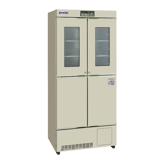
REFRIGERATOR COMPONENTS Refrigerator unit Refrigerator Freezer MPR-414F with drawer rack (optional component) - Page 11 REFRIGERATOR COMPONENTS 1. Circulating fan: This is for cooling the refrigerator uniformly. Fan is installed inside the enclosure. Do not insert anything into the enclosure. The air exhaust vent is located at the upper of the fan. 2. Air intake vent: Ensure this vent is never blocked.
-
Page 12: Control Panel Components
REFRIGERATOR COMPONENTS Control panel components REFRIGERA TOR FREEZER DOOR REF . FREEZ. 1. Door check lamp (DOOR): This lamp is lit when the door is open. 2. Alarm lamp (ALARM): This lamp is flashed during alarm condition. Refer to page 17 “Alarm temperature setting”. -
Page 13: Installation Site
INSTALLATION SITE To operate this unit properly and to obtain maximum performance, install the unit in a location with the following conditions: A location not subjected to direct sunlight Do not install the unit under direct sunlight. Installation in a location subjected to direct sunlight cannot obtain the intended performance. -
Page 14: Installation
INSTALLATION 1. Remove the packaging materials and tapes Remove all transportation packaging materials and tapes. Open the doors and ventilate the unit. If the outside panels are dirty, clean them with a diluted neutral dishwashing detergent. (Undiluted detergent can damage the plastic components. For the dilution, refer to the instruction of the detergent.) After the cleaning with the diluted detergent, always wipe it off... -
Page 15: Start-Up Of Unit
START-UP OF UNIT The following procedures should be adhered to for initial start-up and continuous operation. 1. Connect the unit to dedicated power supply and turn on the power switch. Do not put any product in the unit at this time. Note: If the unit is unplugged or the power to the unit is interrupted, do not restart the unit for at least 5 minutes. -
Page 16: Temperature Setting
TEMPERATURE SETTING Table 1 shows the basic operation method. Perform key operation in the sequence indicated in the table. The example in the table is based on the assumption that the refrigerator temperature is 4 C and the freezer temperature is -25 Note: The unit is set at the factory so that the refrigerator temperature is 5 C and the freezer... -
Page 17: Key Lock Function
KEY LOCK FUNCTION This unit incorporates a key lock feature which can inhibit the tampering using the keys on the control panel. The key lock is set to OFF at the factory. Display Mode Function Key lock OFF Temperature change enabled Key lock ON Temperature change disabled Table 2 Key lock setup procedure (Example: Key lock OFF →... -
Page 18: Defrosting
DEFROSTING Refrigerator The following 2 kinds of defrost methods are adopted for the refrigerator, which control defrosting automatically. Cycle defrost To keep the temperature stable inside the chamber, the refrigeration compressor is cycled on and off. During “off” periods any frost which has accumulated on the evaporator is melted by energizing a heater. This will not have any discernible effect on the chamber temperature. -
Page 19: Alarm Temperature Setting
ALARM TEMPERATURE SETTING The high temperature and low temperature at which the alarm will be activated are effective for freezer and refrigerator. The following shows the outline of the alarm temperature setting. Display Mode Application Settable range High temp. alarm setting C to +14 Refrigerator Low temp. - Page 20 ALARM TEMPERATURE SETTING Table 5 Operation Key operated Indication after operation The current refrigerator temperature ----- is displayed. Press and hold the numerical value The first digit of the temperature shift key for about 5 seconds. display blinks. Set the first digit to 2 with the Pressing the key shifts up the figure numerical value shift key.
-
Page 21: Setting Of Alarm Resume Time
SETTING OF ALARM RESUME TIME The alarm buzzer is silenced by pressing he alarm buzzer stop key (BUZZER) on the control panel during alarm condition. The alarm buzzer will be activated again after certain suspension if the alarm condition is continued. The suspension time can be set by following the procedure shown in the Table 6 below. The example in the table is based on the assumption that the desired duration is 20 minutes. -
Page 22: Alarms And Safety Functions
ALARMS AND SAFETY FUNCTIONS This unit has the alarm and safety functions shown in Table 7, and also a self diagnostic function. Table 7 Alarms and safety functions Kind of alarm Situation Indication Alarm buzzer Safety operation or safety • Refrigerator If the chamber temperature High Alarm lamp flashes. -
Page 23: Routine Maintenance
ROUTINE MAINTENANCE WARNING Always disconnect the power supply to the unit prior to any repair or maintenance of the unit in order to prevent electric shock or injury. Ensure you do not inhale or consume medication or aerosols from around the unit at the time of maintenance. -
Page 24: Replacement Of Lamp
ROUTINE MAINTENANCE Replacement of lamp Follow the procedure below at the time of replacement of the lamp. The lamp is located at the upper front side of refrigerator chamber. 1. Turn off the power switch and disconnect the Lamp power supply plug. (inside) Fig. -
Page 25: Troubleshooting
TROUBLESHOOTING If the unit malfunctions, check out the following before calling for service. In the case of no refrigeration or poor refrigeration, transfer the stored items to another refrigerator or freezer before checking out. Malfunction Check/Remedy If nothing operates even □... - Page 26 DISPOSAL OF UNIT Information on Disposal for Users of Waste Electrical & Electronic Указания за изхвърляне на електрически и електронни отпадъци (за Equipment (private households) битови потребители) This symbol on the products and/or accompanying documents Този символ върху изделия и-или в придружаваща means that used electrical and electronic products should not документация...
- Page 27 DISPOSAL OF UNIT Oplysninger til brugerne om afhændelse af elektriske apparater og Informaţii pentru utilizatori, privind eliminarea echipamentelor electrice şi elektronisk udstyr (private husholdninger) electronice uzate (proprietate particulară) Når produkter og/eller medfølgende dokumenter indeholder Acest simbol, de pe produse şi/sau documentele însoţitoare, dette symbol, betyder det, at elektriske apparater og are semnificaţia că...
- Page 28 DISPOSAL OF UNIT Informace pro uživatele k likvidaci elektrických a elektronických zařízení Informacija naudotojams dėl nenaudojamos elektros ir elektroninės (domácnosti) įrangos utilizacijos (naudojantiems ją buityje) Tento symbol na produktech anebo v průvodních dokumentech Šis simbolis, pažymėtas ant gaminių ir / arba lydimųjų znamená, že použité...
- Page 29 DISPOSAL OF UNIT Informacije za uporabnike o odstranitvi odpadne električne in elektronske Tietoja sähkö- ja elektroniikkalaitteiden hävittämisestä (kotitaloudet) opreme (zasebna gospodinjstva) Tämä symboli tuotteissa ja/tai niiden käyttöohjeissa osoittaa, Ta simbol, ki se nahaja na izdelkih in/ali priloženih dokumentih, että käytettyjä sähkö- ja elektroniikkalaitteita ei saa hävittää pomeni, da se rabljeni električni in elektronski izdelki ne smejo tavallisen kotitalousjätteen mukana.
-
Page 30: Optional Component
OPTIONAL COMPONENT Temperature recorder To record the chamber temperature, an optional temperature recorder is available. Please consult with our sales representative or agent for the installation of temperature recorder. For the proper usage of temperature recorder, refer to an instruction manual included with the temperature recorder. -
Page 31: Installation Of Mtr-0621Lh
OPTIONAL COMPONENT Installation of MTR-0621LH 1. Attach the recorder fixing to the temperature recorder with two screws. (Fig. 1) 2. Remove the screws at the right corner on the top of the Recorder unit and fix the temperature recorder to the attachment fixing position. -
Page 32: Installation Of Mtr-4015Lh
OPTIONAL COMPONENT Installation of MTR-4015LH 1. Remove a cap for the fixing screw on the panel cover for mounting space for a temperature recorder. Panel cover 2. Remove the fixing screw and open the panel cover. (Fig. 1) Shaft 3. Remove the panel cover by pushing the shaft on both Fixing screw side outward. -
Page 33: Installation Of Mtr-G3504A Or Mtr-G3504C
OPTIONAL COMPONENT Installation of MTR-G3504A or MTR-G3504C 1. Remove a cap for the fixing screw on the panel cover for Panel cover mounting space for a temperature recorder. 2. Remove the fixing screw and open the panel cover. Shaft (Fig. 1) 3. -
Page 34: Specifications
SPECIFICATIONS Product name Pharmaceutical Refrigerator Pharmaceutical Refrigerator MPR-414F MPR-414FS External dimensions W800 mm x D600 mm x H1805 mm Internal dimensions W720 mm x D495 mm x H1425 mm (Refrigerator) W317 mm x D440 mm x H576 mm (Freezer) Effective capacity 340 L (Refrigerator), 82 L (Freezer) Exterior Painted steel... -
Page 35: Performance
PERFORMANCE Product name Pharmaceutical Refrigerator MPR-414F Model number MPR-414F-PT MPR-414F-PA MPR-414F-PB MPR-414F-PK MPR-414F-PE MPR-414F-PR Control range Refrigerator: 2 C to 14 C (Ambient temp.; -5 C to +35 C, No load) Freezer: -20 C to -30 C (Ambient temp.; -5 C to +30 C, No load) Noise level... -
Page 36: Safety Check Sheet
CAUTION Please fill in this form before servicing. Hand over this form to the service engineer to keep for his and your safety. Safety check sheet 1. Unit contents: □ □ Risk of infection: □ □ Risk of toxicity: □ □... - Page 40 1-1-1 Sakada, Oizumi-machi, Ora-gun, Gunma 370-0596, Japan Printed in Japan LDCL037200-1 © PHC Corporation 2018 S0418-11118...
Need help?
Do you have a question about the MPR-414FS Series and is the answer not in the manual?
Questions and answers