Please read the operating instructions carefully before using this product, and keep the operating
instructions for future use.
See page 63 for all model numbers.
Operating Instructions
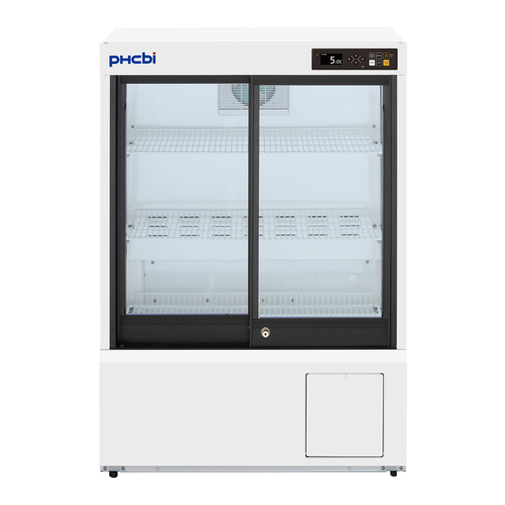
Pharmaceutical Refrigerator
MPR-S150H
MPR-S300H
MPR-S150H
Series


Need help?
Do you have a question about the MPR-S150H Series and is the answer not in the manual?
Questions and answers