Table of Contents
Advertisement
Quick Links
Please read the operating instructions carefully before using this product, and keep the operating
instructions for future use.
See page 63 for model number.
2023/10/3 08:23:26 JST
Verified by KABUMOTO TAKANARI 2023/10/2 16:28:50 JST
Approved by ARAI TAKASHI2 2023/10/2 16:32:28 JST
Operating Instructions
Pharmaceutical Refrigerator
MPR-S1201XH-PA
MPR-S1201RXH-PA
MPR-S1201XH-PA
Advertisement
Table of Contents

Related Manuals for Phcbi MPR-S1201XH-PA


Summary of Contents for Phcbi MPR-S1201XH-PA
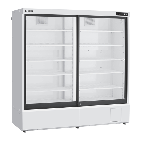
- Page 1 Operating Instructions Pharmaceutical Refrigerator MPR-S1201XH-PA MPR-S1201RXH-PA MPR-S1201XH-PA Please read the operating instructions carefully before using this product, and keep the operating instructions for future use. See page 63 for model number. 2023/10/3 08:23:26 JST Verified by KABUMOTO TAKANARI 2023/10/2 16:28:50 JST...
-
Page 2: Table Of Contents
CONTENTS INTRODUCTION ·························································································4 PRECAUTIONS FOR SAFE OPERATION ·························································5 ENVIRONMENTAL CONDITIONS ································································· 10 SYMBOLS ON UNIT ··················································································· 11 REFRIGERATOR COMPONENTS Main body ···························································································· 12 Control panel ························································································ 14 INSTALLATION SITE ················································································· 16 INSTALLATION ························································································· 17 PLACEMENT OF STORED ITEMS ································································ 19 USE OF SHELVES AND DRAWERS ·····························································... - Page 3 CONTENTS Setting the rail heater ············································································· 49 Setting the date display (format) ······························································· 50 Setting the date ····················································································· 51 Setting the time ····················································································· 52 REMOTE ALARM TERMINAL ······································································ 53 ALARMS AND SELF-DIAGNOSIS ································································· 54 ROUTINE MAINTENANCE Cleaning of exterior, interior, door rail (including drain port) and accessories ······ 56 DEFROSTING ···························································································...
-
Page 4: Introduction
INTRODUCTION Read the operating instructions carefully before using the appliance and follow the instructions for safe operation. Handling of Operating Instructions PHC Corporation never guarantees any safety if the appliance is used for any objects other than intended use or used by any procedures other than those mentioned in the operating instructions. ... -
Page 5: Precautions For Safe Operation
PRECAUTIONS FOR SAFE OPERATION It is imperative that the user complies with the operating instructions as they contain important safety advice. Items and procedures are described so that you can use this unit correctly and safely. Following these precautions will prevent possible injury to the user and any other person. - Page 6 PRECAUTIONS FOR SAFE OPERATION WARNING Never damage the power supply cord or power supply plug (by breaking, adapting, placing near a source of heat, bending with force, twisting, pulling, adding weight, or binding). A damaged power supply cord or power supply plug may cause electric shock, short circuit, or fire. Remove dust from the power supply plug periodically.
- Page 7 PRECAUTIONS FOR SAFE OPERATION WARNING Never store volatile or flammable substances in this unit except in a sealed container. Such substances may cause explosion or fire if they leak. Never insert metal objects such as pins and wires into any vent, gap, or outlet on the unit. This may cause electric shock or injury by accidental contact with moving parts.
- Page 8 PRECAUTIONS FOR SAFE OPERATION WARNING Ask a qualified contractor to carry out disassembly and disposal of the unit. Leaving the unit in a location that can be accessed by third parties may result in unexpected accidents (e.g. the unit may be used for unintended purposes).
- Page 9 PRECAUTIONS FOR SAFE OPERATION CAUTION This unit must be plugged into a dedicated circuit protected by branch circuit breaker. Use a dedicated power source as indicated on the rating label attached to the unit. Multiple socket adaptor may cause fire resulting from abnormal heating. Do not climb on top of the unit or put any objects on the unit.
-
Page 10: Environmental Conditions
ENVIRONMENTAL CONDITIONS This equipment is designed to be safe at least under the following conditions (based on the IEC 61010-1): Indoor use; Altitude up to 2000 m; Temperature 5 C to 40 Maximum relative humidity 80 % for temperature up to 31 C decreasing linearly to 50 % relative humidity at 40 ... -
Page 11: Symbols On Unit
SYMBOLS ON UNIT The following symbols are attached to the unit. The table describes the meaning of the symbols. This symbol is attached to covers that access high-voltage electrical components to prevent electric shock. Only a qualified engineer or service personnel should be allowed to open these covers. -
Page 12: Refrigerator Components
REFRIGERATOR COMPONENTS Main body ① ⑰ ② ② Interior ③ light ⑪ ④ ⑨ ⑤ ⑧ ⑥ ⑦ MPR-S1201RXH ⑩ ⑩ ~ ~ ~ ~ ⑩ ⑯※ ⑬ ⑭ ⑫ ⑮ Back side 2023/10/3 08:23:26 JST Verified by KABUMOTO TAKANARI 2023/10/2 16:28:50 JST Approved by ARAI TAKASHI2 2023/10/2 16:32:28 JST... - Page 13 REFRIGERATOR COMPONENTS ① Control panel: The chamber temperature and other alarms/functions can be set using the keys on the control panel. The operational status can be checked on the temperature display and indicator [page 14]. ② Door switch: This switch detects the door open/close status. The LED lamp on the control panel blinks orange when the door is open.
-
Page 14: Control Panel
REFRIGERATOR COMPONENTS Control panel ① ② ③ ④ ⑤ ⑥ ① LED indicator: In normal operation: The green LED lamp lights up. During alarm condition: The red LED lamp blinks. During notification: The orange LED lamp blinks. During standby status: The orange LED lamp lights up. ②... - Page 15 REFRIGERATOR COMPONENTS ⑩ ⑨ ⑧ ⑦ ⑦ Buzzer stop key (BUZZER STOP): The buzzer is silenced by pressing this key when the buzzer sounds [page 54 and page 55]. The alarm status of remote alarm terminal is not cancelled by pressing the buzzer stop key (BUZZER STOP) since the remote alarm is not linked with the buzzer (The buzzer is silenced).
-
Page 16: Installation Site
INSTALLATION SITE This unit must be installed in a location which meets all the conditions described below. If the unit is installed in a location which does not meet the conditions, its specified performance may not be achieved or malfunctions and accidents may occur. ■... -
Page 17: Installation
INSTALLATION 1. Preparations after unpacking Remove all the tape used to secure the doors and interior parts, and leave the doors open for a short while for ventilation. If any surfaces of the outer cabinet are dirty, wipe the surface using a cloth moistened with a diluted neutral dish-washing detergent. - Page 18 INSTALLATION 5. Setting up the shelves The shelves are packaged at the bottom of the chamber. Set the shelves firmly in place on the shelf stoppers at the standard locations as marked [Fig. 3]. Shelf support <Important> Shelf stopper Do not place anything on the bottom of the chamber. Do not put stored items directly on the bottom of the chamber.
-
Page 19: Placement Of Stored Items
PLACEMENT OF STORED ITEMS Do not place stored items so as to obstruct the air circulation in the chamber. Obstruction of air circulation can cause the freezing of stored items or can impair the temperature distribution in the chamber. Air intake vent Do not block the air intake vent with the stored items. -
Page 20: Use Of Shelves And Drawers
USE OF SHELVES AND DRAWERS <Shelves> Do not place anything on the bottom of the chamber. Do not put stored items directly on the bottom of the chamber. Be careful not to drop the stored items from the front of the shelves when placing the stored items on the shelves and when removing the stored items from the shelves. -
Page 21: Start-Up Procedure
START-UP PROCEDURE Follow this procedure for the initial operation of the unit and for consequent operations (after temporary stoppage for cleaning, maintenance or moving) . After a power failure, the unit will restart operation automatically with the same settings as before the power failure. 1. -
Page 22: Home Screen (Temperature Display Screen)
HOME SCREEN (Temperature display screen) When the standby key is pressed for more than three seconds, the following home screen (temperature display screen) is displayed. For the details of standby key, refer to item ⑥ on page 14. Following shows the integer display mode. Message column ①... -
Page 23: Menu Screen
MENU SCREEN The menu screen is displayed by pressing the menu key (MENU/HOME) while the home screen (temperature display screen) is displayed. Following shows the menu screen. M e n u ① S e t T e m p . 5 C ... - Page 24 MENU SCREEN Following shows the screen display and function at each screen under Menu level. Note: The unit will return from setting mode to the home screen automatically after 90 seconds if no key is operated (auto-return function). In this case, the setting is not changed. Reference Screen Function...
-
Page 25: Setting The Chamber Temperature
SETTING THE CHAMBER TEMPERATURE Set the chamber temperature as required to keep the stored material at an appropriate temperature for a long period of time. Menu Setting range of chamber temperature: between 2 C and 14 Set Temp. ... -
Page 26: Setting The Keypad Lock
SETTING THE KEYPAD LOCK The setting can be locked to avoid accidental changes. When the keypad lock is ON, a change of setting is not accepted even if the key on the control panel is operated. 1. On the home screen, press the menu key (MENU/HOME). Menu ... -
Page 27: Releasing The Keypad Lock
RELEASING THE KEYPAD LOCK When the keypad lock is OFF, a change of setting is accepted. 1. On the home screen, press the menu key (MENU/HOME). Menu LOCK ►The Menu screen is displayed. -
Page 28: Display Of Max/Min Temperature
DISPLAY OF MAX/MIN TEMPERATURE On the temperature display, the maximum and minimum chamber temperature for every 24 or 12 hours can be checked. Initial setting (factory setting): 24 hours 1. On the home screen, press the menu key (MENU/HOME). Menu ... -
Page 29: Reset Of Max/Min Temperature
RESET OF MAX/MIN TEMPERATURE The maximum and minimum chamber temperature can be reset. 1. On the home screen, press the menu key (MENU/HOME). Menu ►The Menu screen is displayed. Set Temp. 5 C Keypad Lock Temp. Max / Min 2. -
Page 30: Setting The Period For Max/Min Temperature
SETTING THE PERIOD FOR MAX/MIN TEMPERATURE The period for monitoring the maximum and minimum chamber temperature is selectable. The monitor period is 24 hours or 12 hours. The maximum and minimum chamber temperature for 24 hours are displayed when 24 hours is selected. The maximum and minimum chamber temperature for 12 hours are displayed when 12 hours is selected. -
Page 31: Display And Export Of Data Log
DISPLAY AND EXPORT OF DATA LOG Display & export of temp. and door operation logs The log of chamber temperature and door operation can be displayed by chart on the screen. Also, those logs can be exported to a USB flash drive. (See page 15 for usable USB flash drives.) 1. - Page 32 DISPLAY AND EXPORT OF DATA LOG 8. By pressing the up or down key, select the date of which data is Date Select displayed. The date is advanced or moved back by one day when the up or down key is 20/04/01 ...
-
Page 33: Export Of Temperature And Door Operation Logs
DISPLAY AND EXPORT OF DATA LOG Export of temperature and door operation logs All temperature logs and door operation logs saved in a memory or log for a selected date (24 hours) can be exported to a USB flash drive. (See page 15 for usable USB flash drives.) Menu ... -
Page 34: Setting The Log Interval
DISPLAY AND EXPORT OF DATA LOG Setting the log interval The log interval for the chamber temperature can be set. When log data reaches the maximum storage amount, the oldest log data is overwritten with the new data. Setting range of log interval: between 1 minute and 15 minutes ... -
Page 35: Setting The Device Id
DISPLAY AND EXPORT OF DATA LOG Setting the device ID The unique device ID indicated on the file exported to a USB flash drive (CSV file) can be set. Setting range of device ID: 6-digit number and alphabet (capital letter only) ... -
Page 36: Display Of Event Log
DISPLAY OF EVENT LOG The event log (max. about 40,000 records) can be displayed on the screen. Following shows the format of the indication. When the number of logs exceeds the maximum number, the oldest log data is overwritten with the new data. E v e n t ... -
Page 37: Export Of Event Log
EXPORT OF EVENT LOG The event log for the selected date or all event logs saved in the memory can be exported to a USB flash drive in CSV file. (See page 15 for usable USB flash drives.) 1. Insert a USB flash drive to the USB port. Menu ... -
Page 38: Setting The Selectable Parameters
SETTING THE SELECTABLE PARAMETERS Selectable parameters The setting of some parameters (including the alarm setting) can be changed. Following shows the selectable parameters. Refer to the following pages for the details. A l a r m s & C o n t r o l s A l a r m s ... -
Page 39: Setting The Temperature Display
SETTING THE SELECTABLE PARAMETERS Setting the temperature display 1. On the home screen, press the menu key (MENU/HOME). Menu ►The Menu screen is displayed. Set Temp. 5 C Keypad Lock Temp. Max / Min 2. By pressing the up or down key, move the cursor to the Alarms & ... -
Page 40: Setting The High-Temperature Alarm
SETTING THE SELECTABLE PARAMETERS Setting the high-temperature alarm An abnormality (chamber temperature rise) is indicated by the blinking of the red LED lamp and the chamber temperature display and the buzzer sounding (15 minutes after blinking) if the chamber temperature exceeds the set value of the high-temperature alarm. Always set an appropriate temperature according to the contents to protect stored items from damage resulting from an increase in temperature. -
Page 41: Setting The Low-Temperature Alarm
SETTING THE SELECTABLE PARAMETERS Setting the low-temperature alarm An abnormality (chamber temperature drop) is indicated by the blinking of red LED lamp and the chamber temperature display and the buzzer sounding (15 minutes after blinking) if the chamber temperature falls below the set value of low-temperature alarm. -
Page 42: Setting The Door Buzzer Delay
SETTING THE SELECTABLE PARAMETERS Setting the door buzzer delay The red LED lamp blinks and “N02:Door Delay ON” is displayed when the door is opened. After a delay, the display is changed to “N01:Door Open” and the buzzer sounds to indicate that the door is open. The delay time (between the blinking of the red LED lamp and the activation of the buzzer) can be changed. -
Page 43: Setting The Buzzer Suspended Period
SETTING THE SELECTABLE PARAMETERS Setting the buzzer suspended period An abnormality is indicated again by the buzzer sounding after a certain period has elapsed (the buzzer recovery time) if the alarm mode continues even after the buzzer has already been silenced by pressing the buzzer stop key (BUZZER STOP). -
Page 44: Setting The Buzzer Volume
SETTING THE SELECTABLE PARAMETERS Setting the buzzer volume The buzzer volume is selectable. Select the appropriate volume taking into consideration of the environment of installation site. Setting range of buzzer volume: Low (small = standard), High (loud) Initial setting (factory setting): Low (small = standard) 1. -
Page 45: Setting The Remote Alarm
SETTING THE SELECTABLE PARAMETERS Setting the remote alarm The alarm of this unit can be relayed to a remote location from this unit by connecting the external alarm device (commercial goods) to the remote alarm terminals. It is selectable whether the operation of the external alarm device is linked with the buzzer or not. -
Page 46: Setting The Interior Light
SETTING THE SELECTABLE PARAMETERS Setting the interior light The condition of the interior light can be selected from three options; link with door operation, always ON, always OFF. Setting range of interior light: link with door operation (AUTO), always ON (ON), always OFF (OFF) ... -
Page 47: Setting The Lighting Time
SETTING THE SELECTABLE PARAMETERS Setting the lighting time The lighting time of the interior light can be selected. The interior light turns off automatically when the setting time has passed. The setting is valid only when the setting of interior light is “AUTO”. ... -
Page 48: Setting The Compressor Delay
SETTING THE SELECTABLE PARAMETERS Setting the compressor delay The delay time before the compressor starts can be changed to reduce the load on the power line and to facilitate the start-up (reset) of the refrigerator during recovery after power failure. <Important>... -
Page 49: Setting The Rail Heater
SETTING THE SELECTABLE PARAMETERS Setting the rail heater This unit has a rail heater installed inside the rail above the door to control condensation on the rail section. The operation mode can be selected from three options; Auto change, always OFF, and always ON. Auto change automatically controls the heater according to the chamber temperature. -
Page 50: Setting The Date Display (Format)
SETTING THE SELECTABLE PARAMETERS Setting the date display (format) The format of date display is selectable between two types. Setting range: year / month / day (YY/MM/DD), or day / month / year (DD/MM/YY) Initial setting (factory setting): year / month / day (YY/MM/DD) 1. -
Page 51: Setting The Date
SETTING THE SELECTABLE PARAMETERS Setting the date 1. On the home screen, press the menu key (MENU/HOME). Menu ►The Menu screen is displayed. Set Temp. 5 C Keypad Lock Temp. Max / Min 2. -
Page 52: Setting The Time
SETTING THE SELECTABLE PARAMETERS Setting the time It is recommended to adjust the time periodically since the deviation of about one minutes per a month may be occurred. 1. On the home screen, press the menu key (MENU/HOME). Menu ►The Menu screen is displayed. ... -
Page 53: Remote Alarm Terminal
REMOTE ALARM TERMINAL The alarm is relayed to a remote location when a remote alarm device (commercially available) is connected to the remote alarm terminal. Installation of a remote alarm device is recommended when the unit is installed in an unattended location so that the operator of the unit is notified of the alarm. Contact our representative or agent to arrange the installation of a remote alarm device. -
Page 54: Alarms And Self-Diagnosis
ALARMS AND SELF-DIAGNOSIS This unit has the alarm functions and self-diagnosis functions listed below. An error code and error message are displayed on the message column when an alarm or self-diagnosis occurs. Contact our sales representative or agent if the alarm mode continues, since the failure of the unit is supposed. - Page 55 ALARMS AND SELF-DIAGNOSIS Error Error message Alarm content Buzzer Remote Chamber code indicator alarm temp. display Door Open Door alarm Blinking of Intermittent orange lamp tone Door Delay ON Delayed status of door alarm Blinking of orange lamp Ref.Temp.High High-temperature alarm Blinking of Blinking orange lamp...
-
Page 56: Routine Maintenance
ROUTINE MAINTENANCE Cleaning of exterior, interior, door rail (including drain port) and accessories Use a dry cloth to wipe off small amounts of dirt on the outside, inside, door rail (including drain port) of the unit and all accessories. If the outside panels are dirty, clean them with a diluted neutral dishwashing detergent. -
Page 57: Defrosting
DEFROSTING The following 2 types of defrosting methods is provided for the refrigerator. Both of them are controlled automatically. Cycle defrosting The refrigerator temperature is kept stable by ON/OFF operation of the compressor. When the compressor is OFF (stopped), the frost on the evaporator is melted by the heater. This defrosting never influences the refrigerator temperature. -
Page 58: Troubleshooting
TROUBLESHOOTING If the unit malfunctions, check the following before calling for service. <Attention> If the malfunction is not resolved after checking the following items or if the malfunction is not shown in the table below, contact our sales representative or agent. Malfunction Check/Remedy If nothing operates even... - Page 59 TROUBLESHOOTING Malfunction Check/Remedy Data cannot be exported to “USB memory is disconnected” the USB flash drive □ USB flash drive is not inserted into the USB port. (Message is displayed) □ USB flash drive is not inserted properly. → Insert a USB flash drive properly into the USB port. □...
-
Page 60: Disposal Of Unit
DISPOSAL OF UNIT WARNING If the unit is to be stored unused in an unsupervised area for an extended period ensure that children do not have access and doors cannot be closed completely. The disposal of the unit should be accomplished by appropriate personnel. Always remove doors to prevent accidents such as suffocation. -
Page 61: Temperature Recorder (Option)
TEMPERATURE RECORDER (OPTION) The chamber temperature can be recorded and checked by installing an optional temperature recorder (MTR-G04A or MTR-0621LH). Contact our sales representative or agent for the purchase of temperature recorder. Main specifications of temperature recorder MTR-G04A MTR-0621LH Recording C to 40 C to 20 range... -
Page 62: Specifications
SPECIFICATIONS Product name Pharmaceutical refrigerator MPR-S1201XH MPR-S1201RXH External dimensions W1800 mm x D650 mm x H1824mm Internal dimensions W1700 mm x D510 mm x H1425 mm Effective capacity 1165 L 1155 L Exterior Painted steel Interior Painted steel Door Highly insulated double glass door Glass: tempered glass Insulation Rigid polyurethane foamed-in place... -
Page 63: Performance
PERFORMANCE Product name Pharmaceutical Refrigerator MPR-S1201XH MPR-S1201RXH Model number MPR-S1201XH-PA MPR-S1201RXH-PA Temperature control range C to 14 C (ambient temperature; -5 C to 35 C, no load) Noise level 42 dB (A scale) Maximum pressure 900 kPa Maximum heat emission... -
Page 64: Safety Check Sheet
SAFETY CHECK SHEET Please fill in this form before servicing. CAUTION Hand over this form to the service engineer for their and your safety. Safety check sheet 1. Stored material □ □ □ Risk of infection: Maybe □ □ □ Risk of toxicity: Maybe □... - Page 65 MEMO 2023/10/3 08:23:26 JST Verified by KABUMOTO TAKANARI 2023/10/2 16:28:50 JST Approved by ARAI TAKASHI2 2023/10/2 16:32:28 JST...
- Page 66 MEMO 2023/10/3 08:23:26 JST Verified by KABUMOTO TAKANARI 2023/10/2 16:28:50 JST Approved by ARAI TAKASHI2 2023/10/2 16:32:28 JST...
- Page 67 MEMO 2023/10/3 08:23:26 JST Verified by KABUMOTO TAKANARI 2023/10/2 16:28:50 JST Approved by ARAI TAKASHI2 2023/10/2 16:32:28 JST...
- Page 68 1-1-1 Sakada, Oizumi-machi, Ora-gun, Gunma 370-0596, Japan Printed in Indonesia LDCL081602-1 © PHC Corporation 2023 N0723-10923 2023/10/3 08:23:26 JST Verified by KABUMOTO TAKANARI 2023/10/2 16:28:50 JST Approved by ARAI TAKASHI2 2023/10/2 16:32:28 JST...
Need help?
Do you have a question about the MPR-S1201XH-PA and is the answer not in the manual?
Questions and answers