
Related Manuals for Phcbi MPR-215F Series


Summary of Contents for Phcbi MPR-215F Series
- Page 1 Operating Instructions Pharmaceutical Refrigerator MPR-215F Series Please read the operating instructions carefully before using this product, and keep the operating instructions for future use. See page 43 for all model numbers.
-
Page 3: Table Of Contents
CONTENTS INTRODUCTION2 PRECAUTIONS FOR SAFE OPERATION ꞏꞏꞏꞏꞏꞏꞏꞏꞏꞏꞏꞏꞏꞏꞏꞏꞏꞏꞏꞏꞏꞏꞏꞏꞏꞏꞏꞏꞏꞏꞏꞏ3 ENVIRONMENTAL CONDITIONS ꞏꞏꞏꞏꞏꞏꞏꞏꞏꞏꞏꞏꞏꞏꞏꞏꞏꞏꞏꞏꞏꞏꞏꞏꞏꞏꞏꞏꞏꞏꞏꞏꞏꞏꞏꞏꞏꞏꞏꞏꞏꞏ7 REFRIGERATOR COMPONENTS Refrigerator unit ꞏꞏꞏꞏꞏꞏꞏꞏꞏꞏꞏꞏꞏꞏꞏꞏꞏꞏꞏꞏꞏꞏꞏꞏꞏꞏꞏꞏꞏꞏꞏꞏꞏꞏꞏꞏꞏꞏꞏꞏꞏꞏꞏꞏꞏꞏꞏꞏꞏꞏꞏꞏꞏꞏꞏꞏꞏꞏꞏꞏꞏ8 Control panel components ꞏꞏꞏꞏꞏꞏꞏꞏꞏꞏꞏꞏꞏꞏꞏꞏꞏꞏꞏꞏꞏꞏꞏꞏꞏꞏꞏꞏꞏꞏꞏꞏꞏꞏꞏꞏꞏꞏꞏꞏꞏꞏꞏꞏꞏꞏ 10 INSTALLATION SITE ꞏꞏꞏꞏꞏꞏꞏꞏꞏꞏꞏꞏꞏꞏꞏꞏꞏꞏꞏꞏꞏꞏꞏꞏꞏꞏꞏꞏꞏꞏꞏꞏꞏꞏꞏꞏꞏꞏꞏꞏꞏꞏꞏꞏꞏꞏꞏꞏꞏꞏꞏꞏꞏꞏꞏꞏ 11 INSTALLATION ꞏꞏꞏꞏꞏꞏꞏꞏꞏꞏꞏꞏꞏꞏꞏꞏꞏꞏꞏꞏꞏꞏꞏꞏꞏꞏꞏꞏꞏꞏꞏꞏꞏꞏꞏꞏꞏꞏꞏꞏꞏꞏꞏꞏꞏꞏꞏꞏꞏꞏꞏꞏꞏꞏꞏꞏꞏꞏꞏꞏꞏꞏꞏꞏ 12 START-UP OF UNIT ꞏꞏꞏꞏꞏꞏꞏꞏꞏꞏꞏꞏꞏꞏꞏꞏꞏꞏꞏꞏꞏꞏꞏꞏꞏꞏꞏꞏꞏꞏꞏꞏꞏꞏꞏꞏꞏꞏꞏꞏꞏꞏꞏꞏꞏꞏꞏꞏꞏꞏꞏꞏꞏꞏꞏꞏꞏ 13 SETTING OF CHAMBER TEMPERATURE ꞏꞏꞏꞏꞏꞏꞏꞏꞏꞏꞏꞏꞏꞏꞏꞏꞏꞏꞏꞏꞏꞏꞏꞏꞏꞏꞏꞏ 14 LOCK OF TEMPERATURE SETTING ꞏꞏꞏꞏꞏꞏꞏꞏꞏꞏꞏꞏꞏꞏꞏꞏꞏꞏꞏꞏꞏꞏꞏꞏꞏꞏꞏꞏꞏꞏꞏꞏꞏꞏꞏ 15 STOP OF FREEZER OPERATION ꞏꞏꞏꞏꞏꞏꞏꞏꞏꞏꞏꞏꞏꞏꞏꞏꞏꞏꞏꞏꞏꞏꞏꞏꞏꞏꞏꞏꞏꞏꞏꞏꞏꞏꞏꞏꞏꞏꞏ... - Page 4 INTRODUCTION Read the operating instructions carefully before using the appliance and follow the instructions for safety operation. PHC Corporation never guarantees any safety if the appliance is used for any objects other than intended use or used by any procedures other than those mentioned in the operating instructions. ...
-
Page 5: Precautions For Safe Operation ꞏꞏꞏꞏꞏꞏꞏꞏꞏꞏꞏꞏꞏꞏꞏꞏꞏꞏꞏꞏꞏꞏꞏꞏꞏꞏꞏꞏꞏꞏꞏꞏ3
PRECAUTIONS FOR SAFE OPERATION It is imperative that the user complies with the operating instructions as it contains important safety advice. Items and procedures are described so that you can use this unit correctly and safely. If the precautions advised are followed, this will prevent possible injury to the user and any other person. - Page 6 PRECAUTIONS FOR SAFE OPERATION WARNING Do not use the unit outdoors. Current leakage or electric shock may result if the unit is exposed to rain water. Only qualified engineers or service personnel should install the unit. The installation by unqualified personnel may cause electric shock or fire. Install the unit on a sturdy floor and take an adequate precaution to prevent the unit from turning over.
- Page 7 PRECAUTIONS FOR SAFE OPERATION WARNING Ensure you do not inhale or consume medication or aerosols from around the unit at the time of maintenance. These may be harmful to your health. Never splash water directly onto the unit as this may cause electric shock or short circuit. Never put containers with liquid on the unit as this may cause electric shock or short circuit when the liquid is spilled.
- Page 8 PRECAUTIONS FOR SAFE OPERATION CAUTION This unit must be plugged into a dedicated circuit protected by branch circuit breaker. Use a dedicated power source as indicated on the rating label attached to the unit. multiple-tap may cause fire resulting from abnormal heating. Connect the power supply plug to the power source firmly after removing the dust on the plug.
-
Page 9: Environmental Conditions ꞏꞏꞏꞏꞏꞏꞏꞏꞏꞏꞏꞏꞏꞏꞏꞏꞏꞏꞏꞏꞏꞏꞏꞏꞏꞏꞏꞏꞏꞏꞏꞏꞏꞏꞏꞏꞏꞏꞏꞏꞏꞏ7
ENVIRONMENTAL CONDITIONS This equipment is designed to be safe at least under the following conditions (based on the IEC 61010-1): Indoor use; Altitude up to 2000 m; Temperature 5 C to 40 Maximum relative humidity 80 % for temperature up to 31 C decreasing linearly to 50 % relative humidity at 40 ... -
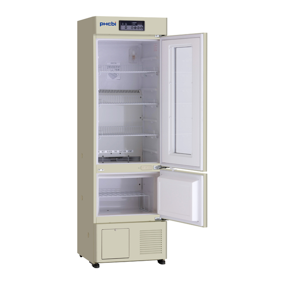
Page 10: Refrigerator Components
REFRIGERATOR COMPONENTS Refrigerator unit Lamp [page 27] Door gasket Refrigerator Freezer Back spacer 11 (inside) [page 12] Caster Remote alarm terminal [page 12] Back side... - Page 11 REFRIGERATOR COMPONENTS 1. Control panel: With the key on the control panel, temperature display can be changed and the alarm buzzer can be canceled. Also, the running status can be checked on the temperature display and the indicators. [page 10] 2.
-
Page 12: Control Panel Components
REFRIGERATOR COMPONENTS Control panel components 1. Door check indicator (DOOR): The red LED lamp is lit when the refrigerator door or freezer door is opened. 2 minutes after the door check indicator is lit, the alarm buzzer is activated to notice the door opening. [page 24] 2. -
Page 13: Installation Site
INSTALLATION SITE To operate this unit properly and to obtain maximum performance, install the unit in a location with the following conditions: A location not compliance with the following conditions may cause poor performance, failure or accident. A location not subjected to direct sunlight Do not install the unit under direct sunlight. -
Page 14: Installation
INSTALLATION 1. After unpackaging Remove all transportation packaging materials and tapes. Open the doors (refrigerator and freezer) and ventilate the unit. If the outside panels are dirty, clean them with a diluted neutral dishwashing detergent. Undiluted detergent can damage the plastic components. For the dilution, refer to the instruction of the detergent. -
Page 15: Start-Up Of Unit
START-UP OF UNIT Follow the procedures below when starting-up (initial and after stop due to the cleaning, maintenance or moving) of the unit. At the recovery from power failure, the operation is start-up automatically with the setting before power failure. -
Page 16: Setting Of Chamber Temperature
SETTING OF CHAMBER TEMPERATURE Set the temperature of refrigerator or freezer according to the usage condition. This unit keeps the storage items for long period with adequate chamber temperature. Refrigerator Freezer Setting range between 2 C and 14 between -35 C and -15 Initial setting (at factory) Example: Changing the refrigerator temperature to 4... -
Page 17: Lock Of Temperature Setting
LOCK OF TEMPERATURE SETTING The temperature setting of chamber can be locked to avoid accidental change. When the lock is ON, the change of refrigerator temperature and freezer temperature is unable even if the key on the control panel is operated. ... -
Page 18: Stop Of Freezer Operation
STOP OF FREEZER OPERATION The freezer operation can be stopped when removing the frost in the freezer chamber or no use of freezer. The current freezer temperature and OFF is displayed alternately when the temperature display indicator for freezer is lit. (Only the current refrigerator temperature is displayed when the temperature display indicator for refrigerator is lit. -
Page 19: Defrosting
DEFROSTING Defrosting of refrigerator The following 2 types of defrosting methods is provided for the refrigerator. Both of them are controlled automatically. Cycle defrosting The refrigerator temperature is kept stable by ON/OFF operation of the compressor. When the compressor is OFF (stopped), the frost on the evaporator is melted by the heater. This defrosting never influences to the refrigerator temperature. -
Page 20: Setting Of Alarm (Refrigerator)
SETTING OF ALARM (REFRIGERATOR) Setting of high temperature alarm The abnormal temperature rise is notified by the blink of alarm indicator and display of refrigerator temperature, and the alarm buzzer (15 minutes after blink) when the high temperature alarm is set. Always set the high temperature alarm to avoid the damage of storage items due to the temperature rise. -
Page 21: Setting Of Low Temperature Alarm
SETTING OF ALARM (REFRIGERATOR) Setting of low temperature alarm The abnormal temperature descent is notified by the blink of alarm indicator and display of refrigerator temperature, and the alarm buzzer (15 minutes after blink) when the low temperature alarm is set. Always set the low temperature alarm to avoid the damage of storage items due to the temperature descent. -
Page 22: Setting Of Alarm (Freezer)
SETTING OF ALARM (FREEZER) Setting of high temperature alarm The abnormal temperature rise is notified by the blink of alarm indicator and display of freezer temperature, and the alarm buzzer (15 minutes after blink) when the high temperature alarm is set. Always set the high temperature alarm to avoid the damage of storage items due to the temperature rise. -
Page 23: Setting Of Low Temperature Alarm
SETTING OF ALARM (FREEZER) Setting of low temperature alarm The abnormal temperature descent is notified by the blink of alarm indicator and display of freezer temperature, and the alarm buzzer (15 minutes after blink) when the low temperature alarm is set. Always set the low temperature alarm to avoid the damage of storage items due to the temperature descent. -
Page 24: Setting Of Alarm Buzzer Recovery
SETTING OF ALARM BUZZER RECOVERY The alarm buzzer recovers and notifies the abnormality again after preset period (alarm buzzer recovery time) if the same alarm status is continued after the alarm buzzer is stopped by pressing the alarm buzzer stop key (BUZZER). Always set the alarm buzzer recovery time to avoid the false recognition of alarm status. -
Page 25: Operation Check After Recovery
OPERATION CHECK AFTER RECOVERY After recovery from a power failure, the unit will resume operation automatically with the setting (refrigerator temperature, freezer temperature, lock of temperature setting, alarm temperature, alarm buzzer recovery time) before power failure. Accordingly, there is no need for re-set however, always check the running status after recovery. -
Page 26: Alarm Functions
ALARM FUNCTIONS This unit has the alarm functions shown below. Contact our sales representative or agent after moving the storage items to other refrigerator or freezer if the alarm status continues because there is a possibility of any failure. Remote alarm Alarms Situation Indication... -
Page 27: Self Diagnostic Functions
SELF DIAGNOSTIC FUNCTIONS This unit has the self diagnostic functions shown below. Contact our sales representative or agent if an error code (ex. E01) is displayed resulting from the self diagnostic. Remote alarm Self diagnostic Situation Indication Alarm buzzer terminal Alarm indicator blinks. -
Page 28: Routine Maintenance
ROUTINE MAINTENANCE WARNING Always disconnect the power supply to the unit prior to any repair or maintenance of the unit in order to prevent electric shock or injury. Ensure you do not inhale or consume medication or aerosols from around the unit at the time of maintenance. -
Page 29: Replacement Of Lamp
ROUTINE MAINTENANCE Replacement of lamp Replace the lamp (bulb) by following the procedure below when the lamp is blown. The lamp is located at the upper right corner of the refrigerator. [Fig. 1] 1. Turn off the power switch and then disconnect the power Lamp supply cord. -
Page 30: Troubleshooting
TROUBLESHOOTING If the unit malfunctions, check out the following before calling for service. <Attention> If the malfunction is not eliminated after checking the following items or the malfunction is not shown in the table below, contact our sales representative or agent. Malfunction Check/Remedy If nothing operates even... -
Page 31: Disposal Of Unit
DISPOSAL OF UNIT WARNING If the unit is to be stored unused in an unsupervised area for an extended period ensure that children do not have access and doors that doors are locked completely with a key. The disposal of the unit should be accomplished by appropriate personnel. Always remove doors to prevent accidents such as suffocation. - Page 32 DISPOSAL OF UNIT Information on Disposal for Users of Waste Electrical & Electronic Указания за изхвърляне на електрически и електронни отпадъци (за Equipment (private households) битови потребители) This symbol on the products and/or accompanying documents Този символ върху изделия и-или в придружаваща means that used electrical and electronic products should not документация...
- Page 33 DISPOSAL OF UNIT Oplysninger til brugerne om afhændelse af elektriske apparater og Informaţii pentru utilizatori, privind eliminarea echipamentelor electrice şi elektronisk udstyr (private husholdninger) electronice uzate (proprietate particulară) Når produkter og/eller medfølgende dokumenter indeholder Acest simbol, de pe produse şi/sau documentele însoţitoare, dette symbol, betyder det, at elektriske apparater og elektronisk are semnificaţia că...
- Page 34 DISPOSAL OF UNIT Informace pro uživatele k likvidaci elektrických a elektronických zařízení Informacija naudotojams dėl nenaudojamos elektros ir elektroninės (domácnosti) įrangos utilizacijos (naudojantiems ją buityje) Tento symbol na produktech anebo v průvodních dokumentech Šis simbolis, pažymėtas ant gaminių ir / arba lydimųjų znamená, že použité...
- Page 35 DISPOSAL OF UNIT Informacije za uporabnike o odstranitvi odpadne električne in elektronske Tietoja sähkö- ja elektroniikkalaitteiden hävittämisestä (kotitaloudet) opreme (zasebna gospodinjstva) Tämä symboli tuotteissa ja/tai niiden käyttöohjeissa osoittaa, Ta simbol, ki se nahaja na izdelkih in/ali priloženih dokumentih, että käytettyjä sähkö- ja elektroniikkalaitteita ei saa hävittää pomeni, da se rabljeni električni in elektronski izdelki ne smejo tavallisen kotitalousjätteen mukana.
-
Page 36: Optional Component
OPTIONAL COMPONENT Temperature recorder To record the chamber temperature, an optional temperature recorder (3 types) is available. Contact our sales representative or agent for the installation of temperature recorder. The available temperature recorder and its location for installation are as follows: Temp. -
Page 37: Installation Of Mtr-0621Lh (1)
OPTIONAL COMPONENT Installation of MTR-0621LH (1) 1. Attach the recorder fixing to the temperature recorder (MTR-0621LH) by referring to the instruction manual enclosed with the temperature recorder. [Fig. 1] Recorder 2. Remove 2 (outside) of 4 screws on the front left of the fixing top panel. -
Page 38: Installation Of Mtr-0621Lh (2)
OPTIONAL COMPONENT Installation of MTR-0621LH (2) 1. Remove a cap for the fixing screw on the panel cover for the space for a temperature recorder. Remove the fixing Fixing screw screw and open the panel cover. Remove the panel cover by pushing the shaft on both sides outward. [Fig. 1] Shaft Panel cover Fig. - Page 39 OPTIONAL COMPONENT 4. Remove the caps (both outside and inside) covering the access port for refrigerator and take out the thermal insulation in the access port. Pass the recorder sensor to the refrigerator through the access port [Fig. 4]. Then replace the thermal insulation and caps (both outside and inside).
-
Page 40: Installation Of Mtr-4015Lh
OPTIONAL COMPONENT Installation of MTR-4015LH 1. Remove a cap for the fixing screw on the panel cover for the space for a temperature recorder. Remove the fixing Fixing screw screw and open the panel cover. Remove the panel cover by pushing the shaft on both sides outward. [Fig. 1] Shaft Panel cover Fig. - Page 41 OPTIONAL COMPONENT 4. Remove the caps (both outside and inside) covering the access port for freezer and take out the thermal insulation in the port. Pass the recorder sensor to the freezer through the access port [Fig. 4]. Then replace the thermal insulation and caps (both outside and inside).
-
Page 42: Installation Of Mtr-G3504A Or Mtr-G3504C
OPTIONAL COMPONENT Installation of MTR-G3504A or MTR-G3504C 1. Remove a cap for the fixing screw on the panel cover for Fixing screw the space for a temperature recorder. Remove the fixing screw and open the panel cover. Remove the panel cover by pushing the shaft on both sides outward. - Page 43 OPTIONAL COMPONENT 5. Remove the caps (both outside and inside) covering the access port for refrigerator and freezer and take out the thermal insulation in the port. Pass the recorder sensor to the chamber through each port [Fig. 5]. Then replace the thermal insulation and caps (both outside and inside).
-
Page 44: Specifications
SPECIFICATIONS Product name Pharmaceutical Refrigerator MPR-215F External dimensions W540 mm x D557 mm + (45)* mm x H1794 mm * projection Internal dimensions W455 mm x D466 mm x H917 mm <Refrigerator> W420 mm x D342 mm x H267 mm <Freezer> Effective capacity 176 L (Refrigerator), 39 L (Freezer) Exterior... -
Page 45: Performance
PERFORMANCE Product name Pharmaceutical Refrigerator MPR-215F Model number MPR-215F-PT MPR-215F-PA MPR-215F-PK MPR-215F-PE MPR-215F-PR Temperature control range Refrigerator: between 2 C and 14 C (ambient temp.; -5 C to 30 C, no load) Freezer: between -20 C and -30 C (ambient temp.; -5 C to 30 C, no load) Noise level... -
Page 46: Safety Check Sheet
CAUTION Please fill in this form before servicing. Hand over this form to the service engineer to keep for his and your safety. Safety check sheet 1. Unit contents: □ □ Risk of infection: □ □ Risk of toxicity: □ □... - Page 48 1-1-1 Sakada, Oizumi-machi, Ora-gun, Gunma 370-0596, Japan Printed in Japan LDCL036900-2 © PHC Corporation 2018 S0418-20119...
Need help?
Do you have a question about the MPR-215F Series and is the answer not in the manual?
Questions and answers
Please tell me the model or number of the fan motor
The model number of the fan motor for the Phcbi MPR-215F Series is not provided in the context.
This answer is automatically generated
How do you clear the F2 alarm when a **** has been replaced after six years?
To clear the F2 alarm on a Phcbi MPR-215F Series after replacing the fan motor, follow these steps:
1. Replace the faulty fan motor.
2. Ensure the unit is powered off before maintenance to prevent electric shock or injury.
3. After replacing the fan motor, power the unit back on.
4. If the alarm persists, contact a sales representative or agent for further assistance.
There is no specific reset procedure mentioned, so professional support may be required if the alarm does not clear automatically.
This answer is automatically generated