Sign In
Upload
Download
Table of Contents
Contents
Add to my manuals
Delete from my manuals
Share
URL of this page:
HTML Link:
Bookmark this page
Add
Manual will be automatically added to "My Manuals"
Print this page
×
Bookmark added
×
Added to my manuals
Manuals
Brands
Phcbi Manuals
Refrigerator
MPR-514R Series
Operating instructions manual
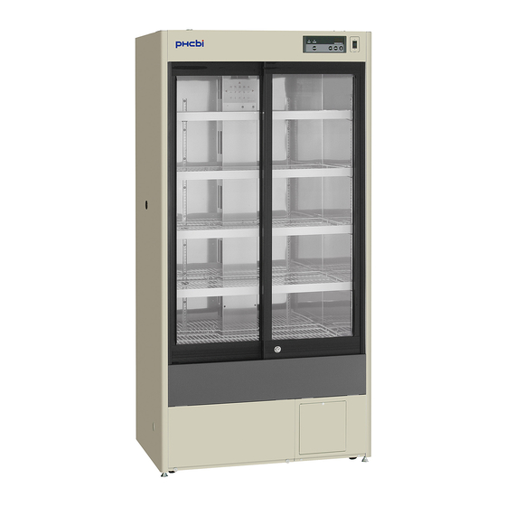
Phcbi MPR-514R Series Operating Instructions Manual
Pharmaceutical refrigerator
Hide thumbs
1
Table Of Contents
2
3
4
5
6
7
8
9
10
11
12
13
14
15
16
17
18
19
20
21
22
23
24
25
26
27
28
29
30
31
32
33
34
35
36
37
38
39
40
41
42
43
44
page
of
44
Go
/
44
Contents
Table of Contents
Troubleshooting
Bookmarks
Table of Contents
Table of Contents
Introduction
Precautions for Safe Operation
Environmental Conditions
Refrigerator Components
Refrigerator Unit
Control Panel Components
Installation Site
Installation
Start-Up of Unit
Cautions for Usage
Chamber Temperature Setting
Lock of Chamber Temperature
Defrost of Evaporator
Alarm Temperature Setting
Setting of High Temperature Alarm
Setting of Low Temperature Alarm
Setting of Delay of Door Alarm
Setting of Ringback of Alarm Buzzer
Operation Check after Recovery
Remote Alarm Terminal
Alarm Functions
Air Circulation Alarm
Self Diagnostic Functions
Safety Functions
Routine Maintenance
Cleaning of Exterior, Interior, and Accessories
Replacement of Fluorescent Lamp
Replacement of Glow Starter
Cleaning of Evaporating Tray
Troubleshooting
Disposal of Unit
Decontamination of Unit
Temperature Recorder
Attachment of MTR-0621LH
Attachment of MTR-G04A or MTR-G04C
Battery for Power Failure Alarm
Setting for Battery before Starting
Specifications
Performance
Safety Check Sheet
Advertisement
Quick Links
1
Chamber Temperature Setting
2
Alarm Functions
3
Self Diagnostic Functions
4
Routine Maintenance
5
Replacement of Fluorescent Lamp
6
Troubleshooting
7
Specifications
Download this manual
Please read the operating instructions carefully before using this product, and keep the operating
instructions for future use.
See page 42 for all model numbers.
Operating Instructions
Pharmaceutical Refrigerator
MPR-514
MPR-514R
MPR-514
Series
Table of
Contents
Previous
Page
Next
Page
1
2
3
4
5
Advertisement
Table of Contents
Need help?
Do you have a question about the MPR-514R Series and is the answer not in the manual?
Ask a question
Questions and answers
Related Manuals for Phcbi MPR-514R Series
Refrigerator Phcbi MPR-514 Series Operating Instructions Manual
Pharmaceutical refrigerator (44 pages)
Refrigerator Phcbi MPR-722 Series Operating Instructions Manual
Pharmaceutical refrigerator (44 pages)
Refrigerator Phcbi MPR-722R Operating Instructions Manual
Pharmaceutical refrigerator (44 pages)
Refrigerator Phcbi MPR-1014R Series Operating Instructions Manual
Pharmaceutical refrigerator (48 pages)
Refrigerator Phcbi MPR-215F Series Operating Instructions Manual
Pharmaceutical refrigerator (48 pages)
Refrigerator Phcbi MPR-S163 Series Operating Instructions Manual
Pharmaceutical refrigerator (36 pages)
Refrigerator Phcbi MPR-S313 Series Operating Instructions Manual
Pharmaceutical refrigerator (36 pages)
Refrigerator Phcbi MPR-1411 Series Operating Instructions Manual
Pharmaceutical refrigerator (36 pages)
Refrigerator Phcbi MPR-721 Series Operating Instructions Manual
Pharmaceutical refrigerator (36 pages)
Refrigerator Phcbi MPR-414FS Series Operating Instructions Manual
Pharmaceutical refrigerator (40 pages)
Refrigerator Phcbi MPR-S150H Series Operating Instructions Manual
Pharmaceutical refrigerator (68 pages)
Refrigerator Phcbi MPR-S300H Series Operating Instructions Manual
Pharmaceutical refrigerator (68 pages)
Refrigerator Phcbi MPR-715F Series Operating Instructions Manual
Pharmaceutical refrigerator (48 pages)
Refrigerator Phcbi MPR-N450FSH Series Operating Instructions Manual
Pharmaceutical refrigerator (69 pages)
Refrigerator Phcbi MPR-N450FH Series Operating Instructions Manual
Pharmaceutical refrigerator (69 pages)
Refrigerator Phcbi MPR-1412R Series Operating Instructions Manual
Pharmaceutical refrigerator (44 pages)
This manual is also suitable for:
Mpr-514 series
Table of Contents
Print
Rename the bookmark
Delete bookmark?
Delete from my manuals?
Login
Sign In
OR
Sign in with Facebook
Sign in with Google
Upload manual
Upload from disk
Upload from URL


Need help?
Do you have a question about the MPR-514R Series and is the answer not in the manual?
Questions and answers