Advertisement
DR
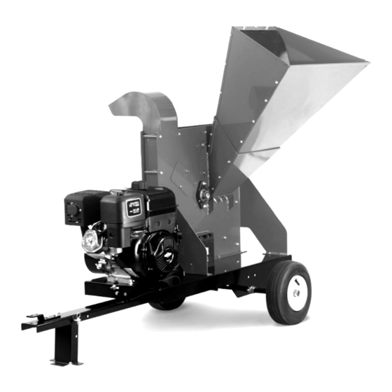
SELF-FEEDING CHIPPER
SAFETY & OPERATING INSTRUCTIONS
MODELS:
16.5 Self-Feeding Chipper
21.0 Self-Feeding Chipper
Serial No.
Order No.
Read and understand this manual and all instructions before operating or servicing this DR SELF-FEEDING CHIPPER.
Original Language
DR Power Equipment
Toll-free phone: 1-800-DR-OWNER (376-9637)
Fax: 1-802-877-1213
Website: www.DRpower.com
Advertisement

Subscribe to Our Youtube Channel
Related Manuals for DR 16.5


Summary of Contents for DR 16.5
- Page 1 MODELS: 16.5 Self-Feeding Chipper 21.0 Self-Feeding Chipper DR Power Equipment Toll-free phone: 1-800-DR-OWNER (376-9637) Serial No. Fax: 1-802-877-1213 Original Language Order No. Website: www.DRpower.com Read and understand this manual and all instructions before operating or servicing this DR SELF-FEEDING CHIPPER.
-
Page 2: Table Of Contents
Additional Information and Potential Changes DR Power Equipment reserves the right to discontinue, change, and improve its products at any time without notice or obligation to the purchaser. The descriptions and specifications contained in this manual were in effect at printing. Equipment described within this manual may be optional. -
Page 3: Chapter 1: General Safety Rules
Labels Your DR SELF-FEEDING CHIPPER carries prominent labels as reminders for its proper and safe use. Shown below are copies of all the safety and operation labels that appear on the equipment. Take a moment to study them and make a note of their location on your DR SELF-FEEDING CHIPPER as you assemble and before you operate the unit. - Page 4 #241991 #241821 #241811 #242041 #241831 #242001 #137581 #242611 (Road-Tow Models only) #242331 (electric start model only) #241841 ® SELF-FEEDING CHIPPER...
- Page 5 Never, under any conditions, remove, bend, cut, fit, weld, or otherwise alter standard parts on the DR SELF-FEEDING Chipper. This includes all shields and guards. Modifications to your machine could cause personal injuries and property damage and will void your warranty.
- Page 6 Allow the engine to cool completely and empty the collector box before storing the DR Leaf and Lawn Vacuum in any enclosure. Remember, decomposing material can generate heat and start a fire. Never store the machine with gas in the tank or a fuel container, near an open flame or spark such as a water heater, space heater, clothes dryer or furnace.
- Page 7 Keep in mind that the operator or user is responsible for accidents or hazards occurring to other people, their property, and themselves. Your DR SELF-FEEDING Chipper is a powerful tool, not a plaything. Exercise extreme caution at all times. The design of this machine is to chip wood. Do not use it for any other purpose. ...
- Page 8 While using the DR SELF-FEEDING Chipper, don't hurry or take things for granted. When in doubt about the equipment or your surroundings, stop the machine and take the time to look things over.
-
Page 9: Chapter 2: Setting Up The Dr Self-Feeding Chipper
This chapter outlines assembly and a few simple steps you will need to follow to set up your new machine before you use it. It may be helpful to familiarize yourself with the controls and features of your DR SELF-FEEDING CHIPPER as shown in Figure 1 before beginning these procedures. - Page 10 Specifications 16.5 Manual and Electric Start Models 21.0 Models Engine Briggs & Stratton (See Engine Manual for Engine Briggs & Stratton Electric Start (See Engine Manual Specifications) for Engine Specifications) Series 1650 2100 Chipping Capacity 4-3/4" Diameter 5-3/4" Diameter Number of...
- Page 11 Hardware Package Parts: Item # Part # Description 1 ... 24197 ..Bolt, 5/16-18 x 4-1/2" ........2 2 ... 14313 ..Nylon Locknut, 5/16-18 ......8 3 ... 15448 ..Nylon Locknut, 3/8-16 ........ 6 4 ... 11152 ..Bolt, 3/8-16 x 1" ........... 5 5 ...
- Page 12 Installing the Tow Bar and Lights for the Road Tow Model Note: For easier installation, keep the machine on the pallet and supports until the Tow Bar is installed. Tools and Supplies Needed: 7/16 Wrench Two 1/2" Wrenches ...
- Page 13 9. Mount a Light Bracket to both sides of the Chipper with two 5/16-18 x 3/4" Light Tail Light Bolts and Locknuts each using two 1/2 Wrenches (Figure 12). Mounting Side Light Bracket 10. Attach the Lights to the mounting brackets with the Locknuts that are included on the Lights using a 7/16"...
- Page 14 Housing Locknuts Two 1/2" Wrenches Support For 16.5 Models: Figure 15a: 16.5 Remove and discard the three Shipping Nuts from the Housing Bolts with two 1/2" Wrenches, but leave the Housing Bolts in place (Figure 15a) Housing Position the Hopper Assembly onto the Housing Support and Stud...
- Page 15 Tow Bar and Leg, reinstall the Pin and secure with the Hitch Clip (Figure Tow Bar 19). Connecting the Battery Cable (Electric Start) We ship the electric-start DR SELF-FEEDING CHIPPER with the negative Pin w/Hitch terminal battery cable disconnected. This prevents the battery from discharging Support Leg Clip during shipment.
- Page 16 To get an accurate reading when checking the oil level: - The machine should be on a level surface. - The dipstick should be pushed all the way down and turned a quarter turn clockwise (16.5) or screwed fully in (21.0 Model) to ensure an accurate oil level reading.
- Page 17 (with a minimum of 85 Octane) to approximately 1" to 1-1/2" below the top of the fill neck to allow for fuel expansion (Figure 21a and 21b). Be careful Figure 22a: 16.5 Model not to overfill and reinstall the Gas Fill Cap before starting the engine. See your Engine Owner’s Manual for more detailed information.
- Page 18 ® SELF-FEEDING CHIPPER...
-
Page 19: Chapter 3: Operating Your Dr Self-Feeding Chipper
Chapter 3: Operating Your DR SELF-FEEDING CHIPPER This chapter covers the procedures for starting and stopping your new DR SELF-FEEDING CHIPPER and discusses basic operation features. The design of this machine is for chipping wood. Never use this machine for any other purpose as it could cause serious injury. - Page 20 The Chipper is designed to accept wood only. The Chipper Knife mounted on a revolving flywheel turns branches fed into the Chipper Hopper into “chips”. Cut your materials into manageable lengths before feeding them into the Chipper Hopper. The chipper hopper must be securely bolted to your DR SELF-FEEDING chipper and the blowback shield in place before using the machine! Use common sense when using the Machine.
- Page 21 Slowly move the Throttle Control Lever all the way to the slow position (turtle icon). 2. For electric start models, turn the Key to the off position to stop the engine. Remove the Key for safety. Note: Close the Fuel Shut-Off when transporting or storing the DR SELF-FEEDING CHIPPER. CONTACT US AT www.DRpower.com...
- Page 22 Connecting the DR Chipper to your Tractor – Yard-Tow Models Lift the Chipper Tow Bar onto the Tractor Hitch and install the Hitch Pin and Hitch Clip to secure it (Figure 28). Pull the Hitch Clip from the Pin and pull the Pin from the Support Leg and Tow Bar (Figure 29).
- Page 23 6. For extra safety and security, you may want to purchase a Lock or Lock Pin to install into the Latch Assembly of the Tow-Hitch Package (Figure 33). 7. Connect the Wire Harness Connector to your Tow Vehicle and ensure that your lights on the Chipper are working properly.
- Page 24 To Free a Jammed Flywheel Shut down the Engine (The flywheel will continue to rotate for a while after the engine is shut off), Wait 5 minutes for the engine to cool and all moving parts to come to a complete stop, remove spark plug wire and disconnect the negative battery cable before moving or working on the chipper.
-
Page 25: Chapter 4: Maintaining The Dr Self-Feeding Chipper
Chapter 4: Maintaining the DR SELF-FEEDING CHIPPER This chapter covers regular maintenance procedures that will ensure the best performance and long life of your DR SELF- FEEDING CHIPPER. For engine maintenance, please refer to the Engine Owner’s Manual that came with your machine. Service intervals listed in the checklist below supersede those listed in the Engine Owner’s Manual. - Page 26 Grease Fittings Your SELF-FEEDING CHIPPER was greased at the Factory. The operator needs to periodically lubricate the two Bearings of the Chipper Assembly. Tools and Supplies needed: Two 1/2" Wrenches Bolt, Flexible hose grease gun Washer Locknut Lithium grease ...
- Page 27 Note: Be sure to use environmentally safe procedures when disposing of the used oil. Removing, Replacing and Adjusting the Drive Belt Oil Check/Fill Use only DR Belts on your machine. The belts have been thoroughly tested and proven for many hours of use. Oil Drain Plug Note: The 16.5 Model has one Belt and the 21.0 has two.
- Page 28 When the Sheave is loose, remove the two Bolts and reinsert them into the original Retaining Bolt holes by hand. Figure 46a: 16.5 Model e) Using the Straightedge, align the Clutch and Sheave by moving the Sheave Bushing in or out on the Flywheel Shaft.
- Page 29 VISUAL inspection of the Chipper Knife (before each use) Routinely check the chipper knife for sharpness. Using a dull knife will decrease performance and cause excessive vibration that will cause damage to the DR SELF-FEEDING Chipper. Tools Needed: ...
- Page 30 Routinely check the wear plate for a sharp square edge. Using a rounded or chipped wear plate will decrease performance and cause excessive vibration that will cause damage to the DR SELF-FEEDING Chipper and make chipping difficult for the operator.
- Page 31 Removing and Replacing the Chipper Knife Rear Access Tools Needed: Cover Locknuts 7/16" Wrench 1/2" Socket with extension 3/16" Allen wrench Awl or Sharp Tool Gloves 1. Loosen the Locknuts that secure the rear Access Cover with a 7/16" Wrench (Figure 51).
- Page 32 If you detect any of these, inspect the machine for damage, or any loose parts. Repair or replace any damaged parts and tighten any loose parts before starting the DR SELF-FEEDING Chipper.
- Page 33 Chipper Knife Sharpening You should never attempt to sharpen the Chipper Knife freehand. Chipper It is extremely important to consistently maintain the 45-degree angle for Knife proper performance (Figure 57). Excessive heat generated during the sharpening process will damage Knives and weaken the metal.
- Page 34 Wear Plate. Removing and Replacing the Wheels The Wheels on the DR SELF-FEEDING Chipper are pneumatic. The Yard-Tow model has pressed in bearings for easy transport. The road tow model has tapered bearings designed for highway use. With use, tires or bearings may need replacing.
- Page 35 The Clutch obtains its power from the Engine RPM. The lower the engagement speed, and the higher the maintained Engine speed, the more torque the Clutch can transfer to the driven unit. NEVER operate the DR SELF-FEEDING CHIPPER Engine at less than full RPM when chipping.
- Page 36 Operate the engine for at least 45 minutes to maintain proper battery charge. If the battery loses its charge, you will need to use a trickle charger (like the DR Battery Charger) to recharge it. The charger should have an output of 12 volts DC at no more than 2 amps.
- Page 37 Recycling a Used Battery Please dispose of your used batteries responsibly by recycling them. Call your local Solid Waste Management District or your local waste handler to locate the collection site nearest you. Some collection sites recycle batteries year-round; others collect them periodically. You can also visit the Website of Earth 911 for more information (www.earth911.org).
-
Page 38: Chapter 5: Troubleshooting
See the Battery Care section in Chapter If your battery is charged and your DR SELF-FEEDING CHIPPER still won’t start, contact us at www.DRpower.com or call 1(800) DR-OWNER (376-9637) for assistance. - Page 39 Knife and tighten the screws. If the machine still exhibits excessive vibration, contact us at www.DRpower.com or call 1(800) DR-OWNER (376-9637) for assistance. The Knife is dull; sharpen or replace it. See Chapter 4. When chipping, the log seems to vibrate ...
- Page 40 Chapter 6: Chipper Accessories Shut down the Engine (The flywheel will continue to rotate for a while after the engine is shut off), Wait 5 minutes for the engine to cool and all moving parts to come to a complete stop, remove spark plug wire and disconnect the negative battery cable before moving or working on the chipper.
- Page 41 Discharge toward the operator position. Confirm that the 180° range of motion is away from the operator zone. Contact us at www.DRpower.com or call 1(800) DR-OWNER (376-9637) if you need assistance. Discharge Ring 3. Line up the Locking Pin hole to the closest hole setting in the Discharge Ring.
-
Page 42: Chapter 7: Parts List And Schematic Diagrams
Chapter 7: Parts List and Schematic Diagrams Parts List – Drive Assembly Note: Part numbers listed are available through DR Power Equipment. Ref# Part# Description Ref# Part# Description 37423 Base, (16.5) 16679 Bolt, HCS, 5/16-18 x 3/4 37424 Base, (21.0) 24246 Shim, Shaft, 1/-1/4, .125 Thk... - Page 43 Schematic – Drive Assembly CONTACT US AT www.DRpower.com...
- Page 44 Parts List - Chipper Basic Assembly Note: Part numbers listed are available through DR Power Equipment. Ref# Part# Description Ref# Part# Description 37770 Sideplate Weldment, Chute (16.5) 24248 Bolt, HCS, 1/2-13 x 1-1/2, Gr5 37771 Sideplate Weldment, Chute (21.0) 37501...
- Page 45 Schematic – Chipper Basic Assembly CONTACT US AT www.DRpower.com...
- Page 46 Parts List – Base and Wheels Assembly – Yard Tow Note: Part numbers listed are available through DR Power Equipment. Ref# Part# Description Ref# Part# Description 37423 Base, (16.5) 37448 Tow Bar 37424 Base, (21.0) 14292 Hitch Plate, Tow Bar 37444 Axle, (16.5)
- Page 47 Schematic – Base and Wheels Assembly – Yard Tow CONTACT US AT www.DRpower.com...
- Page 48 Parts List – Base and Wheels Assembly – Road Tow Note: Part numbers listed are available through DR Power Equipment. Ref# Part# Description Ref# Part# Description 37423 Base, (16.5) 12960 Bolt, HCS, 3/8-16 x 3, Gr5 37424 Base, (21.0) 37466...
- Page 49 Schematic – Base and Wheels Assembly – Road Tow CONTACT US AT www.DRpower.com...
- Page 50 Parts List – Hopper Assembly Note: Part numbers listed are available through DR Power Equipment. Ref# Part# Description Ref# Part# Description 37429 Hopper, Neck, (16.5) 18755 Nut, Nylon Lock, 5/16-18, LP 37430 Hopper, Neck, (21.0) 37439 Shield, Blow Back, (16.5) 37409 Hopper, Top, (16.5)
- Page 51 Schematic – Hopper Assembly CONTACT US AT www.DRpower.com...
- Page 52 Parts List – High Discharge Accessory NOTE: Part numbers listed are available through DR Power Equipment. Ref# Part# Description Ref# Part# Description 24266 Deflector Weldment 14340 Nut, Nylon Lock, 1/4-20 16679 Bolt, HCS, 5/16-18 x 3/4 18258 Hitch Clip 14515...
- Page 53 Notes: CONTACT US AT www.DRpower.com...
- Page 54 Notes: ® SELF-FEEDING CHIPPER...
- Page 55 SELF-FEEDING CHIPPER is fit for ordinary purposes for which a product of this type is used. DR Power Equipment however, limits the implied warranties of merchantability and fitness in duration to a period of two (2) years in consumer use, ninety (90) days for any other use.
- Page 56 Never store the DR SELF-FEEDING Chipper with fuel in the fuel tank inside a building where ignition sources are present, such as hot water and space heaters, clothes dryers and the like. If you are going to drain the fuel tank, do this outdoors. Allow the engine to cool before storing in any enclosure.
Need help?
Do you have a question about the 16.5 and is the answer not in the manual?
Questions and answers