Advertisement
Table of Contents
- 1 Table of Contents
- 2 Chapter 1: General Safety Rules
- 3 Chapter 2: Setting up the DR PRO XL520 CHIPPER-SHREDDER
- 4 Chapter 3: Operating the PRO XL520 CHIPPER-SHREDDER
- 5 Chapter 4: Maintaining the PRO XL520 CHIPPER-SHREDDER
- 6 Chapter 5: Troubleshooting
- 7 Chapter 6: Parts Lists and Schematic Diagrams
- Download this manual
Advertisement
Table of Contents

Related Manuals for DR PRO XL520


Summary of Contents for DR PRO XL520
- Page 1 ® CHIPPER-SHREDDER SAFETY & OPERATING INSTRUCTIONS Model: PRO XL520 DR Power Equipment Serial No. Toll-free phone: 1-800-DR-OWNER (376-9637) Order No. Website: www.DRpower.com Read and understand this manual and all instructions before operating the DR PRO XL520 CHIPPER-SHREDDER.
-
Page 2: Table Of Contents
Table of Contents Chapter 1: General Safety Rules ................................3 Chapter 2: Setting Up the DR PRO XL520 CHIPPER-SHREDDER ...................... 9 Chapter 3: Operating the PRO XL520 CHIPPER-SHREDDER ......................13 Chapter 4: Maintaining the PRO XL520 CHIPPER-SHREDDER ......................18 Chapter 5: Troubleshooting .................................. 32 Chapter 6: Parts Lists and Schematic Diagrams .......................... -
Page 3: Chapter 1: General Safety Rules
Safety and Information labels that appear on the equipment. Take a moment to study them and make a note of their location on your DR PRO XL520 CHIPPER-SHREDDER as you set up and before you operate the unit. Replace damaged or missing Safety and Information labels immediately. - Page 4 Do Not Exceed 10 mph while towing the machine. Become familiar with a chipper equipped with a Yard Tow the operation and service Kit. Never tow the Yard-Tow model recommendations to ensure the over roads. best performance. ® PRO XL520 CHIPPER SHREDDER...
- Page 5 Keep bystanders 50 feet away from your work area at all times. Wood chips and shredder debris exit the mchine at great speeds. To be safe, do not operate the machine near small children or pets, and never allow children to operate the DR PRO XL520 CHIPPER-SHREDDER.
- Page 6 Do not operate the Engine with the Air Cleaner or the Carburetor Air Intake Cover removed. Removal of such parts could create a fire hazard. Do not use flammable solutions to clean the Air Filter. • The Muffler and Engine become very hot and can cause a severe burn; do not touch. ® PRO XL520 CHIPPER SHREDDER...
- Page 7 • Know how to stop the DR PRO XL520 CHIPPER-SHREDDER quickly by turning the key to the “OFF” position (refer to chapter • Never operate your unit on a slippery, wet, muddy, or icy surface. Exercise caution to avoid slipping or falling.
- Page 8 Under California law, and the laws of some other states, you are not permitted to operate an internal combustion engine using hydrocarbon fuels without an Engine Spark Arrestor. This also applies to operation on US Forest Lands. All DR PRO XL520 CHIPPER-SHREDDER’S shipped to California, New Mexico, and Washington State are provided with Spark Arrestors.
-
Page 9: Chapter 2: Setting Up The Dr Pro Xl520 Chipper-Shredder
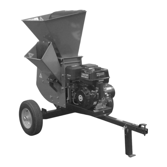
Chapter 2: Setting Up the DR PRO XL520 CHIPPER-SHREDDER It may be helpful to familiarize yourself with the controls and features of your DR PRO XL520 CHIPPER-SHREDDER as shown in Figure 2 before beginning these procedures. If you have any questions at all, please feel free to contact us at www.DRpower.com. - Page 10 Specifications Model PRO XL520 Engine DR 12.0 HP , 420cc E/S (See Engine Manual for Engine Specifications) Oil Type SAE-30 for general use. See page 12 for options Engine Starting Electric w/Recoil Backup Chipping Capacity 5" Diameter Max. Towing Speed...
- Page 11 Compare the contents of the Shipping Crate and the Product Package with the Contents and Hardware Supplied lists above. If you have any questions, contact us at www.DRpower.com or call 1-800-DR-OWNER (376-9637). Do not discard your packaging material until you are fully satisfied with your new DR Figure 4 PRO XL520 CHIPPER-SHREDDER.
- Page 12 Reinstall the Fuel Tank Cap before starting the Engine. See your Engine Owner’s Manual for more detailed information. Note: When Refueling the Fuel Tank, turn the Engine OFF, and let the Engine cool at least five minutes before removing the Fuel Tank Cap. ® PRO XL520 CHIPPER SHREDDER...
-
Page 13: Chapter 3: Operating The Pro Xl520 Chipper-Shredder
This chapter covers the procedures for starting and stopping your new DR PRO XL520 CHIPPER-SHREDDER and discusses basic operation features. It may be helpful to better familiarize yourself with the features of your DR PRO XL520 CHIPPER-SHREDDER by reviewing Figure 2 in Chapter 2 before beginning the steps outlined in this chapter. - Page 14 Connecting the PRO XL520 CHIPPER-SHREDDER to your Tow Vehicle Hitch Always secure the Support Leg in the up (transport) position before towing to prevent damage to the machine. Clevis Pin 1. Lift the Chipper Tow Bar onto the Tow Vehicle Hitch and install the Clevis Pin and Hitch Clip to secure it (Figure 12).
- Page 15 “chips”. The Chipper can chip twigs and branches ranging in size from 1" to 5" in diameter. Cut your materials into manageable lengths of no more than five or six feet long before feeding them into the Chipper Hopper. The Chipper Hopper must be securely bolted to the side of your DR PRO XL520 CHIPPER-SHREDDER before using the machine! •...
- Page 16 Using the Shredder Hopper The Shredder Hopper is located on the top of the DR PRO XL520 CHIPPER-SHREDDER and is the opening into which all materials to be shredded should be fed. You can shred most organic materials. A flexible Blowback Shield is attached to the Hopper.
- Page 17 To Free a Jammed Rotor Before performing any maintenance procedure or inspection, stop the Engine, wait five minutes to allow all moving parts to come to a complete stop and cool. Disconnect the Spark Plug Wire, keeping it away from the Spark Plug. •...
-
Page 18: Chapter 4: Maintaining The Pro Xl520 Chipper-Shredder
Chapter 4: Maintaining the PRO XL520 CHIPPER-SHREDDER Regular maintenance is the way to ensure the best performance and long life of your machine. Please refer to this manual and the Engine Manufacturer's Owner's Manual for maintenance procedures. Service intervals listed in the checklist below supersede those listed in the Engine Manufacturer's Owner's Manual. - Page 19 Removing and Replacing the Engine Oil Oil Drain Tools and Supplies Needed: • Plug Rags • 12mm Wrench • Small Funnel • Approved Container (for Waste Oil) • Engine Oil (see your Engine Manual for Oil specifications) Engine Oil SAE 30 Oil - 37 oz. (1.09 L): above 50 degrees F; 10w-30: 30-90 degrees F;...
- Page 20 Grease Fittings Your PRO XL520 CHIPPER-SHREDDER was greased at the Factory. The Side Bearing operator needs to lubricate the Chipper Side and Drive Side Bearings every 40 Collar Set hours of use. Screw (2 places) Tools and Supplies Needed: •...
- Page 21 • Straightedge CHECKING AND ADJUSTING BELT TENSION Note: The DR PRO XL520 CHIPPER SHREDDER has two drive Belts. Due to Bolts factory tolerances the tension on the two Belts may differ slightly. Over time the Belts will stretch and will begin to closely match each other. This procedure only needs to Figure 22 be performed on one Belt.
- Page 22 The bolts only need to be snug. Do not over tighten. Shaft Key Bushing Retaining 10. Recheck the Belt alignment and repeat alignment procedures as needed. Bolts 11. Reinstall the Belt Guard (Figure 25). Figure 27 ® PRO XL520 CHIPPER SHREDDER...
- Page 23 If you detect any of these, inspect the machine for damage, or any loose parts. Repair or replace any damaged parts and tighten any loose parts before Wear Plate starting the DR PRO XL520 CHIPPER-SHREDDER. Lock Nuts 7. Re-connect the Negative Battery Terminal Wire and Spark Plug Wires.
- Page 24 8. Slide the Knife Access Plate over to align the Lock Nuts with the large holes in the Knife Access Plate and remove the Knife Access Plate. Figure 33 Knife Access Chipper Side Plate Plate Lock Nut Large Hole in Plate Figure 34 ® PRO XL520 CHIPPER SHREDDER...
- Page 25 Rotate the Rotor Assembly using a Stick until the three Allen Screws Access attaching the Knife to the Rotor are visible through the Access Opening Opening (Figure 35). 10. Clean out the heads of the Allen Screws with an Awl or Sharp Tool. 11.
- Page 26 NOTICE: Do not reuse Flange Nut that you remove from the Hammer Shaft Figure 39 during this procedure. Order new hardware from DR Power Equipment for replacement. Damage may occur if used hardware is installed. Before performing any maintenance procedure or inspection, stop the Engine, wait five minutes to allow all parts to cool.
- Page 27 Socket wrench with 9/16" Deep Socket • Marker or Tape • (4) Flange Nut, 3/8-24 (DR part #A0005092914) To prevent accidental Starter engagement, disconnect the Battery Negative Bolts Terminal using two 5/16" wrenches, and disconnect the Spark Plug Wire Figure 40 Remove the three Bolts supporting the Belt Guard using a 3/8"...
- Page 28 27. Tighten the Screen Pivot Bolt, Upper Scroll Bolt and Lower Scroll Bolt. Opening Flange Nut 28. Reinstall the Belt Guard (Figure 40). 29. Re-connect the Negative Battery Terminal Wire and Spark Plug Wires. Hammers Existing Spacers New Spacer New Hammer Shaft Figure 48 ® PRO XL520 CHIPPER SHREDDER...
- Page 29 The Clutch obtains its power from the Engine RPM. The higher the maintained Engine speed, the more torque the Clutch can transfer to the driven unit. NEVER operate the DR PRO XL520 CHIPPER-SHREDDER Engine at less than full RPM. •...
- Page 30 Dust Cap Removing and Replacing the Wheels The Wheels on the DR PRO XL520 CHIPPER SHREDDER are pneumatic and have tapered bearings. With use, Tires and Bearings may need replacing. The following procedure will explain how to replace the Wheel.
- Page 31 Operate the Engine for at least 45 minutes to maintain proper Battery charge. If the Battery loses its charge, you will need to use a trickle charger (like the DR Battery Charger) to recharge it. The Charger should have an output of 12 volts at no more than 2 amps.
-
Page 32: Chapter 5: Troubleshooting
Most problems are easy to fix. Consult the Troubleshooting Table below for common problems and their solutions. If you continue to experience problems, contact us at www.DRpower.com or call toll-free 1-800-DR-OWNER (376-9637) for support. Shut down the Engine, remove the Spark Plug Wire, and wait 5 minutes before performing any maintenance procedure or inspection on the DR PRO XL520 CHIPPER-SHREDDER. - Page 33 Remove any built-up debris from the DR PRO XL520 CHIPPER-SHREDDER Hopper Inlet(s) and Discharge Chute. The inner Shoes of the Clutch are worn, and/or the Clutch Shoe Retaining Springs are weak or broken. Change the Clutch (refer to “Chapter 4: Maintaining the DR PRO XL520 CHIPPER- SHREDDER”). Shredding and chipping ...
-
Page 34: Chapter 6: Parts Lists And Schematic Diagrams
Chapter 6: Parts Lists and Schematic Diagrams Parts List – Shredder Assembly Note: Part numbers listed are available through DR Power Equipment. Ref# Part# Description Ref# Part# Description 10000041629 Spacer-Hammer 110721 Nut-Nylon Lock 1/2-13 10000041665 Hammer-Serrated 111521 Bolt-HCS 3/8-16 X 1 Gr5 Zp... - Page 35 Schematic –SHREDDER ASSEMBLY CONTACT US AT www.DRpower.com...
- Page 36 Parts List –Frame and Drive Assembly Note: Part numbers listed are available through DR Power Equipment. Ref# Part# Description Ref# Part# Description A0001609606 Engine, DR 12.0 HP, 420cc E/S, 110761 Nut, Nylon Lock, 5/16-18 w/Labels 111411 Bolt, HCS, 5/16-18 X 3", GR5, ZP 10000043555 Clutch, Centrifugal, 1"...
- Page 37 Schematic – Frame and Drive assembly CONTACT US AT www.DRpower.com...
- Page 38 Notes: ® PRO XL520 CHIPPER SHREDDER...
- Page 39 PRO XL520 CHIPPER-SHREDDER is fit for ordinary purposes for which a product of this type is used. DR Power Equipment however, limits the implied warranties of merchantability and fitness in duration to a period of two (2) years in consumer use, ninety (90) days for any other use.
- Page 40 • If your DR PRO XL520 CHIPPER-SHREDDER will be idle for more than 30 days, we recommend using a gas stabilizer. This will prevent sediment from gumming up the Carburetor. If there is dirt or moisture in the gas or Tank, remove it by draining the Tank.
Need help?
Do you have a question about the PRO XL520 and is the answer not in the manual?
Questions and answers