Table of Contents
Advertisement
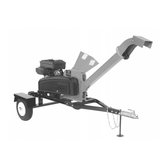
DR CHIPPER
Operating & Assembly Instruction Manual
Model: 18.0 HP
TLC18-CHP
This manual contains information concerning proper and improper
operating procedures, warnings, maintenance, troubleshooting,
assembly, and tips. Everyone who operates this machine should
read these instructions and be thoroughly familiar with them.
P/N 913-0268
12/31/03
Advertisement
Table of Contents

Related Manuals for DR TLC18-CHP


Summary of Contents for DR TLC18-CHP
- Page 1 DR CHIPPER Operating & Assembly Instruction Manual Model: 18.0 HP TLC18-CHP This manual contains information concerning proper and improper operating procedures, warnings, maintenance, troubleshooting, assembly, and tips. Everyone who operates this machine should read these instructions and be thoroughly familiar with them.
-
Page 2: Section I - Safety
This machine can DANGER : Your chipper was built to be operated according to the rules for safe operation in this manual. As with any type of power equipment, carelessness or error on the part of the operator can result in serious injury. If you violate any of these rules, you may cause serious injury to yourself or others. - Page 3 WARNING : The Engine Exhaust from this product contains chemicals known to the state of California to cause cancer, birth def MAKE CERTAIN THAT ALL SAFETY LABELS ON THIS EQUIPMENT ARE KEPT CLEAN AND IN GOOD CONDITION. IF YOU NEED REPLACEMENT LABELS, ORDER BY PART NUMBER.
- Page 4 091-0057 091-0059 091-0062 091-0088 091-0093...
- Page 5 091-0256 091-0378 091-0379 091-0380 091-0381...
- Page 6 091-0384 913-0265...
-
Page 7: Safe Operation Practices
Keep in mind that the operator or user is responsible for accidents or hazards occurring to other people, their property, and themselves. • Your chipper is a powerful tool, not a plaything. Exercise extreme caution at all times. Your unit has been designed to chip. Do not use it for any other purpose. •... - Page 8 • Never place your hands, feet, or any part of your body in the chipper chute, discharge opening, or near or under any moving part while the engine is running. Keep clear of the discharge opening at all times. If it becomes necessary to push material into the chipper chute, use a small diameter stick, NOT YOUR HANDS.
- Page 9 Adjust towing speed for terrain and conditions. Do not exceed 45 MPH when towing. • Because the is no suspension on the chipper, it will tend to bounce more on rough roads. Be extra cautious when towing over bumpy or rough terrain including railroad crossings.
-
Page 10: Your Responsibility
Only operate your chipper from the operator zone. • Know how to turn your unit off. • Never move your chipper or leave it unattended with the engine running. • Do not operate your chipper on concrete or blacktop. •... -
Page 11: Section Ii - Assembly Instructions
STEP II – ASSEMBLING THE CHIPPER HOPPER 1. Assemble chipper hopper (item #20) to the basic machine using four each 5/16”-18 x 3/4” carriage bolts (item #19), 5/16” flatwashers(item #3), and 5/16”-18 nylock nuts(item #10),. Put head of bolt inside hopper with threads sticking out. - Page 12 STEP IV – ATTACHING THE DISCHARGE CHUTE 1. Loosen the two 5/16-18 x 4” bolts on the chipper enough that the mounting plates on the discharge chute (item #7, pg. 29) will slide onto the bolts. You may have to slightly tap the nut side of the bolt to center it before the discharge chute can easily slide into place.
- Page 13 STEP V – ATTACHING THE SWIVEL TOP AND DEFLECTOR 1. Get three 5/16-18 X ¾” carriage bolts (item #2, pg. 29), two 5/16-18 nylock nuts (item #5, pg. 29), three 3/8” flat-washers(item #60, pg. 30), and the locking knob (item #12, pg 29) from the bolt bag. 2.
- Page 14 STEP VI – ATTACHING THE WIRE HARNESS Identify the “road side” and “curb side” of your trailer per the picture below. The mounting brackets have an access hole in them so the wire harness can be attached to the light. On the wire harness the yellow/brown wire is for the road side light and the green/brown wire is for the curb side light.
-
Page 15: Section Iii - Operation
BEFORE STARTING ENGINE, ALWAYS CHECK OIL LEVEL! Refer to the engine owner’s manual for further details regarding OPERATION AND MAINTENANCE OF the engine. NOTE: ENGINE IS SHIPPED WITHOUT OIL! FILL CRANKCASE WITH OIL BEFORE STARTING ENGINE. BE VERY CAREFUL NOT TO ALLOW DIRT TO ENTER THE ENGINE WHEN CHECKING OR ADDING OIL OR FUEL. -
Page 16: Checking And Adding Oil
• Check oil level before starting the engine. • Check level daily, or after every eight hours. • Keep oil level at FULL. • Do not overfill. Oil filling procedure: first add 1 quart. Start and run engine at idle for 30 seconds. Shut engine off and wait 30 seconds. -
Page 17: Starting And Stopping
• Always wear protective gloves and safety glasses during operation of the chipper. • If it becomes necessary to push material into the chipper hopper, only use a wood stick, never your hands or anything steel. -
Page 18: Section Iv - Chipping
• If branches are 2” or larger in diameter, feed only one branch at a time into the chipper. • If branches are smaller than 2”, more than one at a time can be fed into the chipper. - Page 19 LIMBS. • CHECK TO SEE THAT THE FLYWHEEL WILL TURN FREELY BEFORE YOU START THE CHIPPER. • VISUALLY CHECK CHIPPER KNIFE FOR DAMAGE EACH TIME YOU USE YOUR CHIPPER. • CHECK KNIFE CONDITION, WEAR PLATE CONDITION, GAP SETTING AND THE NUTS AND BOLTS THAT HOLD THE KNIFE IN PLACE FOR TIGHTNESS EVERY 8-10 HOURS OF OPERATION.
-
Page 20: To Free A Jammed Flywheel
• Remove both spark plug wires and keep away from spark plugs. • Disconnect battery at negative terminal. • Remove any material left in the chipper hopper. • Remove discharge chute weldment. NOTE: Never pry against the scroll weldment when removing the discharge chute or at any other time. -
Page 21: Section V - Maintenance And Storage
Check for loose parts, bolts, and nuts. 1. When not in use, your chipper should be stored out of the reach of children. Be sure there are no gasoline fumes in the storage area. For long periods of storage (over winter), refer to the engine owner’s manual. -
Page 22: Knife Sharpening
• How many times a knife can be sharpened is determined by how much material needs to be taken off to sharpen or to compensate for dents or gouges. • A new chipper knife has 5/16” measurement between the short side bevel edge and the knife mounting holes. See figure 2. -
Page 23: Knife Installation
• Visually inspect and clean the knife. • Hand tighten the knife to the chipper disk with bolts and nylock locking nuts. If you are installing a new knife, use the new hardware that comes with the knife when attaching it to the chipper disk. -
Page 24: Changing Oil
BE SURE TO REINSTALL THE KNIFE CORRECTLY AND DOUBLE CHANGING OIL • Your chipper is equipped with an oil drain valve to make changing the oil easy. • The valve is located on the engine, on the towing side of the machine. -
Page 25: Belt Replacement
BELT ADJUSTMENT The belt on your chipper should deflect 3/8” under three pounds of pressure as shown in figure 1 below. If it doesn’t, adjust per the following directions. • Remove belt guard. • Loosen engine bolts. • Tighten or loosen the nut on the belt tensioner until you have the correct tension as shown in figure 1. -
Page 26: Troubleshooting
Flywheel won’t turn. Chipping action seems too slow or flywheel stalling. When chipping, log seems to vibrate excessively & “hammers” hands. Chipper knife is hitting wear plate. Engine runs but flywheel doesn’t rotate. TROUBLESHOOTING PROBLEM Clutch is slipping or flywheel is jammed or stopped. -
Page 27: Lubrication And Maintenance
• Check belt tension. • Check all nuts and bolts for tightness. • Check engine oil. • Check chipper knife for sharpness. • Check knife and wear plate gap. • Clean air filter. • Grease bearings in basic chipper. -
Page 28: Installation
CENTRIFUGAL CLUTCH INSTALLATION AND SERVICING INSTRUCTIONS REMOVAL 1. Remove clutch from shaft by removing bolt and washers. 2. Slide clutch off shaft. 3. Remove key from keyway. INSTALLATION 1. Clean the shaft and remove any burrs. 2. Install spacer onto shaft. 3. -
Page 29: Section Vi - Parts List & Assembly Drawings
SECTION VI – PARTS LIST & ASSEMBLY DRAWINGS TLC18-CHP PARTS LIST ITEM # PART # 030-0325 090-0462 913-0375 090-0233 090-0460 913-0232 913-0284 090-0066 913-0252 913-0253 913-0258 500-0051 090-0088 090-0394 913-0224 913-0327 090-0438 030-0193 703-0424 030-0237 030-0211 913-0328 911-0214 090-0633 704-0106... - Page 30 TLC18-CHP PARTS LIST ITEM # PART # 090-0234 3/8 USS FLATWASHER 408-0078 SAFETY CHAIN 911-0220 HITCH TUBE WELDMENT 913-0218 TRAILER HITCH 090-0370 1/2-13 X 3" HHCS 090-0123 3/8-16 X 3 1/2" HHCS 913-0223 NEGATIVE BATTERY CABLE 500-0039 3/16" COTTER PIN...
- Page 33 913-0232 CHIPPER BASIC MACHINE ITEM # PART # 090-0048 030-0115 090-0233 090-0049 030-0117 090-0024-3 090-0162 913-0210 913-0034 090-0460 913-0270 090-0642 913-0271 913-0236 913-0279 090-0470 090-0245 090-0077 090-0462 913-0375 913-0326 090-0677 090-0121 913-0021 913-0334 030-0118 090-0676 913-0376 090-0504 090-0643 DESCRIPTION 5/16-18 GRIPCO LOCKNUT...
- Page 35 NOTES...
- Page 36 NOTES COUNTRY HOME PRODUCTS Meigs Road, P.O. Box 25, Vergennes, Vermont 05491 1(800) DR-OWNER (376-9637) 12/31/03...
Need help?
Do you have a question about the TLC18-CHP and is the answer not in the manual?
Questions and answers