
Subscribe to Our Youtube Channel
Related Manuals for Anritsu MT8820A


Summary of Contents for Anritsu MT8820A
- Page 1 MT8820A Radio Communication Analyzer Operation Manual Fifth Edition Read this manual before using the equipment. Keep this manual with the equipment. ANRITSU CORPORATION Document No.: M-W1943AE-5.0...
- Page 2 BEFORE using the equipment. Some or all of the following five symbols may not be used on all Anritsu equipment. In addition, there may be oth- er labels attached to products which are not shown in the diagrams in this manual.
- Page 3 3. This equipment cannot be repaired by the user. DO NOT attempt to open the cabinet or to disassemble internal parts. Only Anritsu- Repair trained service personnel or staff from your sales representative with a knowledge of electrical fire and shock hazards should service this equipment.
- Page 4 For Safety CAUTION 1. Keep the power supply and cooling fan free of dust. • Clean the power inlet regularly. If dust accumulates around the Cleaning power pins, there is a risk of fire. • Keep the cooling fan clean so that the ventilation holes are not ob- structed.
- Page 5 This battery must be replaced by a service engineer when it has reached the end of its useful life; contact the Anritsu sales section or your nearest representative. Note: The battery used in this equipment has a maximum useful life of 7 years.
- Page 6 Anritsu Corporation will not accept liability for equipment faults due to unforeseen and unusual circumstances, nor for faults due to mishandling by the customer. Anritsu Corporation Contact If this equipment develops a fault, contact Anritsu branch offices or its representa- tives at the address in this manual.
- Page 7 Notes On Export Management This product and its manuals may require an Export License/Approval by the Government of the product's country of origin for re-export from your country. Before re-exporting the product or manuals, please contact us to confirm whether they are export-controlled items or not. When you dispose of export-controlled items, the products/manuals are needed to be broken/shredded so as not to be unlawfully used for military purpose.
- Page 8 CE Marking Anritsu affixes the CE Conformity Marking on the following product (s) in accor- dance with the Council Directive 93/68/EEC to indicate that they conform with the EMC directive of the European Union (EU). CE Conformity Marking 1. Product Model...
- Page 9 3. Applied Standards EMC: Emission: EN61326: 1997/A1: 1998 (Class A) Immunity: EN61326: 1997/A1: 1998 (Annex A) Performance Criteria IEC61000-4-2 (ESD) IEC61000-4-3 (EMF) IEC61000-4-4 (Burst) IEC61000-4-5 (Surge) IEC61000-4-6 (CRF) IEC61000-4-8 (RPFMF) IEC61000-4-11 (V dip/short) *: Performance Criteria A: During testing normal performance within the specification limits. B: During testing, temporary degradation, or loss of function or which is self-recovering.
- Page 10 Anritsu affixes the C-tick marking on the following product (s) in accordance with the regulation to indicate that they conform with the EMC framework of Austra- lia/New Zealand C-tick marking 1. Product Model Model: MT8820A Radio Communication Analyzer Software: MX882000B W-CDMA Measurement Software...
-
Page 11: About This Manual
About This Manual The MT8820A Radio Communication Analyzer is a measuring instrument plat- form that allows both transmitter/receiver characteristics measurement in mobile communication systems and call processing tests with one unit. When using MT8820A, confirm that installed measurement software of specifica- tions and test method that are supported by mobile systems must be installed. - Page 12 Checking Accessories When unpacking, check that the products listed in the attached component list are provided. If a missing or damaged component is found, please contact Anritsu or its distributors. The following components are provided with this product. For details, refer to “1.3 Product Configuration”...
- Page 13 This section explains the name and function of each part, installation of MT8820A, and connection method with external devices. Section 3 Getting Started This section explains the operation flow of MT8820A from turning On the power and measuring to turning Off the power. Section 4 Basic Operation This section explains the basic operation procedure of MT8820A.
- Page 14 Notations in This Manual Notation (font) Example Meaning Indicates a panel key. Character strings printed on the panel key or Local function name (incase there is no printing) are written. Indicates to press a panel key after Shift pressing This procedure is Shift + Shift + Recall...
-
Page 15: Table Of Contents
Table of Contents For Safety ............ About This Manual........Section 1 Product Overview ..... Product Overview ............Features................ Product Configuration ........... Specifications..............Section 2 Setup.......... Part Names and Functions ........... Installation..............2-18 Connection..............2-22 Memory Card ..............2-34 Section 3 Getting Started ...... - Page 16 Section 4 Basic Operation......Display Area..............Operating a Cursor ............Operating a Screen ............Operating a Window ............. 4-14 Operating a User Menu..........4-17 Operating a Function Menu .......... 4-18 Setting Parameters ............4-27 Tag Operation ............... 4-35 Operating a Template ........... 4-38 4.10 Operating a View Window..........
- Page 17 Section 8 Remote Control Commands ..Command List by Function........... Command Specifications in Alphabetical Order ... 8-11 Section 9 Maintenance ......Performance Test ............Calibration..............9-25 Cleaning................ 9-28 Storage and Transportation.......... 9-29 Troubleshooting ............9-31...
- Page 18 VIII.
- Page 19 Section 1 Product Overview This section explains the overview, product configuration and specifications of MT8820A. Product Overview ............1-3 Features..............1-3 Product Configuration..........1-4 1.3.1 Standard configuration ........1-4 1.3.2 Options ............1-4 1.3.3 Measurement software and options ....1-5 1.3.4 Application parts..........
- Page 20 Section 1 Product Overview...
-
Page 21: Product Overview
(5) Parameter save/recall All the measurement parameters set to MT8820A can be saved as a file, which eliminates the need for repeating similar setting for each measurement. (6) Listing the function menu... -
Page 22: Product Configuration
CA68ADP PC card adopter For CF card 1.3.2 Options The following table lists options for expanding the functions of MT8820A. All the options are to be ordered separately. For ordering them, specify the model name/symbol, product name and quantity. Table 1-3-2-1 Options... -
Page 23: Measurement Software And Options
1.3 Product Configuration 1.3.3 Measurement software and options Measurement software and options available for MT8820A is to be ordered sepa- rately. For detailed function and performance of the measurement software, please contact Anritsu or your nearest distributor. The following table lists measurement software products and options available for MT8820A. -
Page 24: Warranty Service
Section 1 Product Overview 1.3.5 Warranty service Table 1-3-5-1 Warranty service Model name/ Product name Remarks Symbol MT8820A-90 3-year Warranty Service MT8820A-91 5-year Warranty Service... -
Page 25: Specifications
1.4 Specifications 1.4 Specifications The following tables show the specifications for MT8820A: Table 1-4-1 Specifications Item Specifications General Frequency range: 30 to 2700 MHz Maximum input level: +35 dBm (Main 1) Main 1 input/output connector • Impedance: 50 Ω • VSWR ≤ 1.2 (≤ 1.6 GHz), ≤ 1.25 (1.6 to 2.2 GHz), ≤ 1.3 (> 2.2 GHz) •... - Page 26 Display • Color TFT LCD, Size: 8.4", Number of dots: 640 × 480 dots External control • GPIB: Controlled by an external controller, assuming the MT8820A as a device (except some functions such as power switch etc.). No controller function •...
-
Page 27: Setup
Section 2 Setup This section explains names and functions of each parts, installation method of MT8820A and connection procedures with external devices. Part Names and Functions ........2-3 2.1.1 Exterior ............2-3 2.1.2 Front panel ............ 2-4 2.1.3 Rear panel............. 2-14 Installation.............. - Page 28 Section 2 Setup...
-
Page 29: Part Names And Functions
The front panel is composed of the LCD panel, panel keys and connectors. The rear panel includes the power inlet, GPIB connector, etc. On the sides of MT8820A are provided two grips for transporting MT8820A and an exhaust fan. Rear panel... -
Page 30: Front Panel
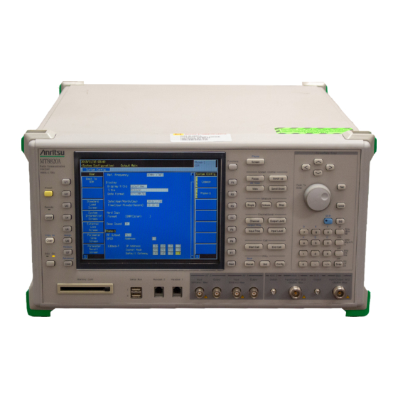
Fig. 2-1-2-1 Front panel (1) Preset Preset key Starts initialization. Remote Remote lamp Illuminates while MT8820A is operating in the remote control mode. Local Local key Switches from remote control operation mode to local control mode. Copy Copy key Performs hard copy of a current screen. - Page 31 2.1 Part Names and Functions Fig. 2-1-2-2 Front Panel (2) U1 , U2 , U3 , U4 , U5 , U6 , U7 User function keys Execute user menu contents displayed in the leftmost area of the screen. + U6 Shift Assign Assign key Currently not available.
- Page 32 Section 2 Setup Fig. 2-1-2-3 Front panel (3) Serial Bus 1 Serial bus connector 1 Currently not available. 10. Serial Bus 2 Serial bus connector 2 Currently not available. 11. Handset 2 Handset connector 2 Currently not available. 12. Handset 1 Handset connector 1 Handset connector (RJ11) used for a voice communication test on Phone 1.
- Page 33 2.1 Part Names and Functions Fig. 2-1-2-4 Front panel (4) – AF connector AF connectors 13. AF2 Input AF2 input connector Currently not available. 14. AF2 Output AF2 output connector Currently not available. 15. AF1 Input AF1 input connector A BNC input connector used for AF measurement on Phone 1. The voice codec and audio board options are required.
- Page 34 Section 2 Setup Fig. 2-1-2-5 Front panel (5) – RF connector RF connectors 17. AUX2 Output AUX2 auxiliary output connector Currently not available. 18. Main2 Input/Output Main2 input/output connector Currently not available. 19. AUX1 Output AUX1 auxiliary output connector SMA type auxiliary output connector used for RF measurement on Phone 1. 20.
- Page 35 2.1 Part Names and Functions Fig. 2-1-2-6 Front panel (6) F1 , F2 , F3 , F4 , F5 , F6 , Function keys Executes function menu items displayed in the rightmost area of the screen. Next Page switch key Switches pages of the menu displayed in the rightmost area of the screen.
- Page 36 Section 2 Setup Fig. 2-1-2-7 Front panel (7) Screen control keys (Screen Control) Focus Focus key Switches between windows to be operated. View View key Opens/Closes the View window. Shift View Alt View Alt View key Switches between View windows to be displayed. Scroll Up Up scroll key Scrolls up screens or windows.
- Page 37 Sets the output level. Input Level Input level key Sets the input level. Call processing keys (Call) Start Call Phone call key Makes a call from MT8820A to a phone. End Call Network-side ending key Releases communications with a phone from MT8820A. 2-11...
- Page 38 Section 2 Setup Fig. 2-1-2-9 Front panel (9) Utility key Recall Recall key Starts reading parameter files. Recall Shift Save Save key Starts saving of parameter files. Standard key Starts change of the system. Config Configuration key Opens the Configuration menu. Cursor operation/data entry keys (Cursor/Data Entry) ∧...
- Page 39 2.1 Part Names and Functions Fig. 2-1-2-10 Front panel (10) Cursor operation/data entry keys (Cursor/Data Entry) <continued> Shift Shift key Press this key, before executing functions indicated in blue on the panel. Back space key Deletes one character before the cursor, while a value is being entered. 47.
-
Page 40: Rear Panel
Section 2 Setup 2.1.3 Rear panel Fig. 2-1-3-1 Rear panel (1) GPIB-1 GPIB connector 1 Remote control connector for Phone 1 through GPIB GPIB-2 GPIB connector 2 Currently not available. Event Trig Out-1 Trigger output connector 1 BNC connector for outputting the event timing to external device allocated to Phone 1. - Page 41 2.1 Part Names and Functions Fig. 2-1-3-2 Rear panel (2) 10 MHz Buff Out Reference signal output connector BNC connector for outputting a reference signal from MT8820A. Freq Adjust Frequency adjustment Adjuster knob for the reference oscillation frequency. 10. Call Proc I/O-2 call processing input/output port 2 Currently not available.
- Page 42 An interface for packet or communication test allocated to Phone 1. 19. Grounding terminal Connect a grounding lead here to ground MT8820A to the ground potential. 20. Power inlet Power cable inlet. Permissible power range is 100 to 120 Vac or 200 to 240 Vac (47.5 to 63 Hz).
- Page 43 Turns the main power to On or Off. Turning the main power switch on, power switch on the front panel turns standby (Stby). 22. Safety labels WARNING label for safe operation of MT8820A. Observe the description on the label. WARNING NOOPERATOR SERVICE- ABLE PARTS INSIDE.
-
Page 44: Installation
Section 2 Setup Installation Install MT8820A after you have taken it from a package box and have checked the packed items. This section explains how to install it and precautions before use. 2.2.1 Transportation Carry MT8820A with the grips provided on both sides of it and keeping it horizontal. -
Page 45: Installation
Install MT8820A horizontally in a stable place at a low-drift temperature between 0 and 50°C. Keep the rear and sides of MT8820A at least 10 cm apart from obstacles such as walls and peripherals in order to provide space around the exhaust holes. - Page 46 × Place where it is exposed to active gas Avoid installing MT8820A in a place that may be ex- posed to active gas. Otherwise MT8820A may be damaged, thus causing a fire accident and/or failure.
-
Page 47: Piggyback Installation
× Using MT8820A with dust accumulated on the fan 2.2.3 Piggyback installation To install two units of MT8820A in a piggyback structure, mate four feet (at the cor- ners of the bottom of the upper unit) with four adjusters (at the corners of the top of the lower unit). -
Page 48: Connection
Insert the plug of the power cable into the power outlet. 2.3.2 Checking the power voltage CAUTION To operate MT8820A normally, observe the power voltage range described below. If a power voltage not specified below is used, electric shock or fire accident, failure, and/or malfunction may occur. -
Page 49: Protective Grounding
WARNING Powering on MT8820A without protective grounding may cause human accidents due to electric shock. In case a 3- pole (ground-type 2-pole) power outlet is not available,... -
Page 50: Connecting To A Phone
Section 2 Setup 2.3.4 Connecting to a phone Methods for connecting MT8820A to a phone to be measured differ according to AF of a phone, RF connector type or assignment. This section explains the basic connec- tion method. Note: To perform RF signal measurement, check that output connector of MT8820A is in conformance with the RF Output setting (Refer to “6.1.10 Setting the... -
Page 51: Connecting A Gpib Cable
2.3 Connection 2.3.5 Connecting a GPIB cable MT8820A is provided with GPIB connector as remote control interface. Connect the connector of the GPIB cable to GPIB-1 on the rear panel. GPIB GPIB connector ≤20 m Total cable length ≤4 m... -
Page 52: Rs-232C Port
Section 2 Setup 2.3.6 RS-232C port The RS-232C (D-SUB, 9 pins, female) port is connector for performing data com- munication test between MT8820A and a phone. Table 2-3-6-1 Signal assignment of RS-232C connector Pin No. Signal name Description CF (DCD) -
Page 53: Reference Signal Input/Output Connector
2.3 Connection 2.3.8 Reference signal input/output connector The BNC-type 10 MHz/13 MHz Ref In connector on the rear panel of MT8820A is a connector inputting an external reference signal. Input the signal with the fre- quency accuracy of ±1 ppm and the level of 2 to 5 Vp-p. -
Page 54: The Call Processing Port
Section 2 Setup 2.3.10 The call processing port The Call Proc I/O connector (D-SUB, 15 pins) on the rear panel of MT8820A is used to input/output signals related to the call-processing test. Pin assignment varies, depending on the measurement software. Check the meas- urement software to be used. - Page 55 SYNC IN Input the synchronization signal of the TTL or CMOS level from the master unit, when two units of MT8820A are synchronously operated. SYNC OUT Outputs the synchronization signal of the CMOS level to the slave unit, when two units of MT8820A are synchronously operated.
- Page 56 Connect the Call Proc. I/O connector (DSUB 15-pin) on the rear panel to that on MT8820A using the connection cable provided with MN8110A. This allows in- put/output of the MT8820A Call Proc. I/O connector input/output signal with the BNC connector.
- Page 57 Synchronization signal input connector SYNC Input Synchronization signal output connector SYNC Output Table 2-3-10-3 Relationships between front panel connector and MT8820A Call Proc I/O connector When using W-CDMA, GSM or PDC measurement software MN8110A front panel Call Proc. I/O on MT8820A Connector name...
- Page 58 SYNC Output SYNC OUT Fig. 2-3-10-3 Rear panel Call Proc. I/O MT8820A interface connector Core Fig. 2-3-10-4 Connection between MT8820A and MN8110A Table 2-3-10-5 MN8110A standards 213 mm (W), 44 mm (H), 150 mm (D) Dimensions (projecting items not included) Mass...
-
Page 59: Checking Power To Be Input To Connector
2.3.11 Checking power to be input to connector Avoid feeding a power exceeding the maximum permissible power to input connec- tors of MT8820A. Do not input signals to connectors dedicated for output or the internal circuits should be damaged. Table 2-3-11-1 Maximum permissible power... -
Page 60: Memory Card
2.4.1 Precautions for use Note the following points when using a memory card: (1) Never remove a memory card while MT8820A is accessing the card. Other- wise data saved on the card may be lost and besides the card itself may be dam- aged. -
Page 61: Getting Started
Section 3 Getting Started This section outlines the basic procedures for using MT8820A, from power-on to power-off. For details of each operation when power is on, refer to Section 4 to 6 of this manual or operation manual for the measurement software Power-on .............. - Page 62 Section 3 Getting Started...
-
Page 63: Power-On
0°C, drops of water produced inside may constitute a short circuit thus causing failure. To power on MT8820A, turn on both the main power switch on the rear panel and the power switch on the front panel. [Procedure] Turn on the main power switch on the rear panel. -
Page 64: Initialization
When the power is turned On, perform initialization. Initialization aims at returning the parameters set for MT8820A in the default status. Initialization prevents MT8820A from being influenced by the previous setting. For details, refer to “5.1 Initialization.” [Procedure] Press Preset to display the Preset popup window Fig. -
Page 65: Selecting A Screen
Selecting a Screen Select a screen corresponding to the items to be set after initialization. Functions and operation status of MT8820A depends on the screen. Select measurement screen (RF-1 Screen) to set or measure a parameter. Measure- ment screen is the general name for screens in which measurements are performed. -
Page 66: Viewing A Screen
Section 3 Getting Started Viewing a screen This section explains how to view a screen using the Fundamental Measurement screen of W-CDMA measurement software as an example. For details, refer to “4.1 display Area.” Fig. 3-4-1 W-CDMA•Fundamental Measurement screen Date and time Shows date and time, or user-defined character string. - Page 67 3.4 Viewing a screen The phone currently being measured and measurement software When Phone-1 is being measured, shows the measurement software being used. The first connector, such as Main 1 or GPIB-1, is used. Function menu Functions to be executed by pressing the corresponding function key on the right hand side.
-
Page 68: Calibration
Band Calibration and Full Calibration can be performed by a single MT8820A unit. Band Calibration performs calibration within the band of the communication system supported by the measurement software. -
Page 69: Setting A Parameter
3.6 Setting a Parameter Setting a Parameter Set parameters for measurement conditions on the screen setting (Parameter) window to be measured. To operate a window such as setting window, the window must be active. For de- tails of window operations, refer to “4.4 Operating a window”. Example: Changing Reference Level from −10.0 dBm to −15.0 dBm in the setting win- dow on the W-CDMA measurement software Fundamental Measurement... - Page 70 Section 3 Getting Started Fig. 3-6-3 Input Level selection Press the encoder to open the pop up window and start entry of values. The upper and lower limits for input values are displayed. Fig. 3-6-4 Starting to enter Use the numeric keypad to enter a value to be changed. To enter −15.0 dBm, +/−...
-
Page 71: Measurement
3.7 Measurement Measurement Start measurement after all the parameters necessary for measurement have been specified, the terminal to be tested has been prepared and the state of MT8820A has been checked. For details, refer to “5.3 Starting a Measurement”. [Procedure] Single . -
Page 72: Reading Measurement Results
Section 3 Getting Started Reading Measurement Results When the measurement has been completed, read the measurement results. The measurement results are displayed in the measurement results window of the meas- urement screen. Example: To read measurement results for Occupied Bandwidth in W-CDMA meas- urement software. - Page 73 3.8 Reading Measurement Results F3 : “Occupied Bandwidth” to display the measurement results for Press Occupied Bandwidth. Other measurement results can be viewed by turning the encoder. Fig. 3-8-3 Displaying measurement results 3-13...
-
Page 74: Power-Off
Section 3 Getting Started Power-Off Power Off MT8820A when it is not used. Turn Off both the main power switch on the rear panel and the power switch on the front panel. [Procedure] Hold down the power switch on the front panel for at least one second to turn it Off. -
Page 75: Basic Operation
Section 4 Basic Operation This section explains basic operation required for a measurement including screen description, how to enter parameters and execute functions. Display Area .............. 4-3 4.1.1 Names and positions in display area .... 4-3 4.1.2 Status area ............ 4-4 4.1.3 Measurement-indicator/error-status area.. - Page 76 Section 4 Basic Operation 4.7.3 Parameter setting procedures....... 4-28 4.7.4 Setting a list selection type parameter ..4-28 4.7.5 Setting a numeric value type parameter ..4-29 4.7.6 Setting a numeric value group type parameter ............4-31 4.7.7 Setting a character string parameter..... 4-32 4.7.8 Setting channel, frequency or level....
-
Page 77: Display Area
4.1 Display Area Display Area This section explains the contents displayed on LCD of MT8820A. Display posi- tion is determined according to the display contents. 4.1.1 Names and positions in display area The screen consists of the following seven display areas. Some areas are not dis- played depending on the operation statuses. -
Page 78: Status Area
The screen type currently being opened is displayed. It indicates operation mode for MT8820A. Output connector/status for RF signal Connector type or status for RF signal output from MT8820A is displayed. Output connector for RF signal can be set in RF Output on the System Configu- ration screen. -
Page 79: Measurement-Indicator/Error-Status Area
4.1 Display Area Measurement mode The current measurement mode is displayed. This is displayed only during measurement. Table 4-1-2-2 Measurement mode Display Measurement mode Single Single measurement mode Continuous Continuous measurement mode Window list bar The types and active/inactive status of the opened windows are displayed. Phone under measurement and measurement software The phone under measurement and the software type are displayed. -
Page 80: User Menu Area
4.1.5 Window area Window area displays parameters and measurement results indicating MT8820A set- tings and measurement conditions. Format and content of a window area differs depending on the screen or window. For some screens, two windows are displayed in upper and lower areas. -
Page 81: Operating A Cursor
4.2 Operating a Cursor Operating a Cursor The cursor is used to scroll the screens and windows, select a desired parameter or digit of numeric value, and activate a tag. 4.2.1 Cursor type The cursor can be classified as follows according to their shapes and functions. In this manual, the all the types are called “cursor”... -
Page 82: Moving A Cursor
Section 4 Basic Operation (3) Menu cursor Cursor displayed in the popup windows for all menus by pressing Functions . It selects a function menu. Fig. 4-2-1-3 Menu cursor 4.2.2 Moving a cursor The cursor is moved in the following ways: Table 4-2-2-1 Operating a cursor Cursor Operation... -
Page 83: Operating A Screen
4.3 Operating a Screen Operating a Screen Screen indicates current operation status. Executable functions, display contents and settable parameters vary depending on the screen. To execute a desired func- tion, select a screen that allows to execute the function. 4.3.1 Screen type The screens vary depending on the measurement software. - Page 84 Section 4 Basic Operation (1) Press Screen to open the screen selection list and select any screen Normally, press Screen to select a screen. Select any screen from the Screen Select popup window displayed by pressing Screen . Example: To select the System Information screen: (one of the common screen) [Procedure] Press Screen to display the Screen Select popup window.
- Page 85 4.3 Operating a Screen (2) Executing the screen select function of the user menu A screen can be opened by executing the screen select function of the user menu. Screen name such as System Information Screen are displayed in the user menu. Example: To open System Information screen from System Configuration screen System Information screen is opened by pressing U4 : System Information Screen...
-
Page 86: Scrolling A Screen
Section 4 Basic Operation 4.3.3 Scrolling a screen When the scroll bar is displayed at the right edge of the screen (on the left of the function menu), scrolling enables the items that have remained to be displayed. Fig. 4-3-3-1 Scroll bar The screen is scrolled by one of the following ways: Table. -
Page 87: Change The Screen Color Pattern
4.3 Operating a Screen 4.3.4 Change the screen color pattern It is possible to change the color of the letters, background or other details shown on the screen. There are five color patterns to choose from on the measurement screen. Next Press to move to the Color Setting menu. -
Page 88: Operating A Window
Section 4 Basic Operation Operating a Window The window is a field to set the measurement condition parameter and display the measurement result. The window is displayed only in the measurement screen, which is unique for each screen. 4.4.1 Window type Windows can be classified as follows. -
Page 89: Activating A Window
4.4 Operating a Window 4.4.3 Activating a window Focus Focus Press to activate the window to be operated. Each time Focus pressed, active window changes in sequence. Press until the desired window becomes active. 4.4.4 Changing the window size To display more parameters and items in a window, enlarge the window size. The window size can only be changed in the vertical direction on the screen. -
Page 90: Scrolling A Window
Section 4 Basic Operation 4.4.5 Scrolling a window As with the screen, the window can be scrolled up and down when the scroll bar is displayed. Scrolling the window is effective only for an active window. The window scrolling operations are described in the table below. Table 4-4-5-1 Scrolling a window Scrolling the window Operation... -
Page 91: Operating A User Menu
4.5 Operating a User Menu Operating a User Menu User menu is the executable function list displayed in each screen or window. Up to U7 are displayed and user menu is executed by to seven functions: pressing the corresponding user function keys. User menus are displayed only on the common screen and are all screen select func- tion menus. -
Page 92: Operating A Function Menu
Section 4 Basic Operation Operating a Function Menu Function menu is displayed in each screen or window and executed by pressing the function keys on the right of the menu to be executed. 4.6.1 Viewing a function menu The number of function menu items displayed on one screen is 7 ( F1 to F7 ). -
Page 93: Switching A Menu Page
4.6 Operating a Function Menu 4.6.2 Switching a menu page When a screen or window has seven or more functions, menus are displayed by switching the pages. Next Next Press to switch the menu page. Press to change the page. Example: To switch from page1 to 2 of the function menu. - Page 94 Section 4 Basic Operation Next Press Page 2 of the function menu is displayed. Fig. 4-6-2-2 Page 2 of the function menu 4-20...
-
Page 95: Displaying The Menu List Of All
4.6 Operating a Function Menu 4.6.3 Displaying the menu list of all pages Menus in all the pages for displayed menu title can be displayed as a list. Press Functions to display all menus. Fig. 4-6-3-1 Displaying the all menu list 4-21... -
Page 96: Types Of Function Menus
Section 4 Basic Operation Operations described in a table below are performed in a popup window for all menus. Table 4-6-3-1 Operating popup window for all menus popup window for all menus Operation Functions Display/hide all menus • Turn the encoder to the left Move the cursor upward ∧... -
Page 97: Execution Menu
4.6 Operating a Function Menu 4.6.5 Execution menu Press function key in the execution menu to set execution status for displayed func- tion. Screen selection function and calibration execution function are included in the execution menu. Fig. 4-6-5-1 Example of an execution menu Example: To execute Full Calibration on the measurement screen Press F6 : Full Calibration to execute Full Calibration. -
Page 98: Character String Entry Menu
Section 4 Basic Operation For multiple entry items, the cursor selects one entry item. If an entry item is Enter on the right of the cursor, press encoder or to determine the nu- meric value of the current cursor position and move to the next item on the right. -
Page 99: Item Selection Menu
4.6 Operating a Function Menu 4.6.9 Item selection menu This menu is displayed by executing the item display menu. Options on menu title are displayed. Press function key for item selection to select one of the options. Fig. 4-6-9-1 Example of an item selection menu 4-25... -
Page 100: Tag Selection Menu
Section 4 Basic Operation 4.6.10 Tag selection menu By pressing the function key for tag selection menu, the selected tag is activated and displayed at the top of the screen or window. Operations are similar to the execu- tion menu. TAG mark is displayed on the left of the tag selection menu. -
Page 101: Setting Parameters
4.7 Setting Parameters Setting Parameters Setting status and measurement conditions are called parameter. In this section, procedures for setting parameters are explained for each parameter type. 4.7.1 Settable parameters Parameters displayed on the setting window can be classified into two types: one that can be changed the value and one that is only for display and no value can be changed. -
Page 102: Parameter Setting Procedures
Section 4 Basic Operation 4.7.3 Parameter setting procedures Manual parameter setting is performed by procedures below regardless of a parame- ter type. [Procedure] Move the cursor onto the parameter to be set. Start entry. Select parameter or enter numeric values or character strings. Determine the entered value. -
Page 103: Setting A Numeric Value Type Parameter
4.7 Setting Parameters 4.7.5 Setting a numeric value type parameter The procedure for setting a numeric-value-type parameter is as follows: [Procedure] Turn the encoder to move the cursor onto the parameter to be set. Perform one of the following operations to start entry. •... - Page 104 Section 4 Basic Operation Determine the value by one of the following operations. Unit is set to the one displayed on the popup window. • Press the encoder • Press Enter • Press Popup window is closed and entered value is displayed. +/−...
-
Page 105: Setting A Numeric Value Group Type Parameter
4.7 Setting Parameters 4.7.6 Setting a numeric value group type parameter The procedure for setting a numeric-value-group-type parameter is as follows: [Procedure] Turn the encoder to move the cursor onto the parameter to be set. Perform one of the following operations to start entry. •... -
Page 106: Setting A Character String Parameter
Section 4 Basic Operation 4.7.7 Setting a character string parameter The procedure for setting a character-string-type parameter is as follows: [Procedure] Turn the encoder to move the cursor onto the parameter to be set. Perform one of the following operations to start entry. •... -
Page 107: Setting Channel, Frequency Or Level
4.7 Setting Parameters 4.7.8 Setting channel, frequency or level Pressing the channel level key of the panel key ease the operation to set the in- put/output channel, frequency and level on the measurement screen. Table 4-7-8-1 Parameter and channel level key Parameter Channel level key Channel... - Page 108 Section 4 Basic Operation ∧ , ∨ , Pressing after turning the encoder or pressing < > deletes all the displayed value. +/− Press one of the following keys if the numeric keypad, is pressed at the end of operations in the entry area. •...
-
Page 109: Tag Operation
4.8 Tag Operation Tag Operation Tag is generic name for parameters and display items, which is displayed on the left side of a screen or a window. Each parameter and measurement result belonging to Tag is displayed under the tag. By tracing a tag, parameters and display items can be found speedily. -
Page 110: Activating A Tag
Section 4 Basic Operation 4.8.2 Activating a tag A tag can be activated by the following operation (1) Move the cursor onto the parameter belonged to the tag. (2) Move the cursor within the tag display area. (3) Execute the tag selection menu in the function menu. (1) Move the cursor onto a parameter belonged to the tag In the common screen or setting window, tag can be activated by moving the cursor onto a parameter belonged to the tag. -
Page 111: Jump To A Tag
4.8 Tag Operation (3) Execute the tag selection menu in the function menu Function menu marked with “TAG” is the tag selection menu. By executing the function menu on which tag name to be activated is written, the tag is activated. Example: To activate the Occupied Bandwidth tag on the Fundamental Measurement screen/measurement result window of the W-CDMA measurement software. -
Page 112: Operating A Template
Section 4 Basic Operation Operating a Template Template is to judge the measurement result waveform. A template can be opened when a mark as shown in the figure below is displayed in the setting window. Fig. 4-9-1 Template mark Note: The screen cannot be switched to another measurement screen when a tem- plate is opened. -
Page 113: Operating A View Window
4.10 Operating a View Window 4.10 Operating a View Window Open the view window to display the measurement waveform. A view window can be displayed for each tag in the measurement result window on the measurement screen. For a tag that can display the view window, a view window mark as shown in the figure below is displayed on the right of the tag. - Page 114 Section 4 Basic Operation 4-40.
-
Page 115: Using Common Functions
Section 5 Using Common Functions This section explains the operation procedure of the common functions for the meas- urement software such as initialization, measurement start and methods for sav- ing/reading parameters. Refer to Section 6 for the common screen functions. Initialization .............. - Page 116 Section 5 Using Common Functions...
-
Page 117: Initialization
5.1 Initialization Initialization Before starting a new measurement, perform initialization. Initialization returns all the parameters to the known state to prevent from being affected by the previous op- erations. The procedure for initialization is as follows. [Procedure] Press Preset to open the Preset menu. Press F1 : Preset to execute the initialization. -
Page 118: Calibration
Calibration is performed after power is turned on or a terminal to be tested is changed. Band Calibration and Full Calibration can be performed by a single MT8820A unit. Band Calibration performs calibration within the band of the communication system supported by the measurement software. -
Page 119: Calibrating All Input/Output Bands
Full Calibration performs calibration on the RF input/output bands (30 to 2700 MHz) for MT8820A. Full Calibration is performed when the MT8820A is turned on. The time for the last Full Calibration is displayed at “Full CAL Time” field on Sys- tem Information screen. -
Page 120: Starting A Measurement
Section 5 Using Common Functions 5.3 Starting a Measurement A measurement is performed on the measurement screen (RF-1 Screen). A meas- urement cannot be performed on the Common Screen. Common screen on which a measurement cannot be performed • System Configuration screen •... -
Page 121: Starting A Measurement In The Synchronous Single Mode
5.3 Starting a Measurement 5.3.4 Starting a measurement in the Synchronous single mode [Procedure] Transmits SWP command on the measurement screen. Example of programming by remote control 5.3.5 Stopping a measurement Stop To stop a measurement under execution, press on the front panel. Under remote control, measurement start commands SNGLS, S2 (single) or CONT, S1 (continuous mode) are used. -
Page 122: Connecting A Call
This clause explains the basic operations using a panel key. 5.4.1 Connecting a call Connecting a call means establishing communication status between MT8820A and a phone being tested. To connect a call, call from MT8820A (network) or from the phone being tested to MT8820A. Note: To connect a call, the call processing status must be in idle (wait). -
Page 123: Ending A Call
A call can be ended from MT8820A (network) or from the phone, just as when connecting a call. Note: To end a call, the call processing status must be in communication. The term indicating communication status varies depending on the measurement soft- ware. -
Page 124: Hard Copy
Section 5 Using Common Functions 5.5 Hard Copy Hard copy is a function to save an image displayed on LCD of MT8820A in the file. This function is useful for recording the measurement result or waveform or pasting on a report. -
Page 125: Functions Can Be Set Only For The Remote Control
SCREEN ON 5.6.3 Outputting non-modulation CW signals Normally, RF signals output from MT8820A are modulated signal. However, out- put of non-modulation CW signal may be required in the special occasion such as a performance test. Return to the normal mode that outputs the modulation signal when a performance test completes. -
Page 126: Setting A Processing At An Error Occurrence
Section 5 Using Common Functions 5.6.5 Setting a processing at an error occurrence Sets a processing for the case when an error occurred. (1) Normal mode Continues the processing for succeeding commands ignoring an occurrence of an error. An error pup-up window for the occurred error is displayed only at the error occurrence, but deleted when the succeeding command is processed. -
Page 127: Common Screen Functions
Section 6 Common Screen Functions This section explains the functions and procedures on common screen such as the System Configuration screen and System Information screen. Setting Systems and Interfaces......... 6-3 6.1.1 Opening the System Configuration screen ... 6-3 6.1.2 Viewing the System Configuration screen ..6-4 6.1.3 Setting the reference frequency .... - Page 128 Section 6 Common Screen Functions...
-
Page 129: Setting Systems And Interfaces
6.1 Setting Systems and Interfaces Setting Systems and Interfaces This clause explains setting method for MT8820A systems such as reference fre- quency, date and time, and interfaces such as GPIB. Systems and interfaces are set on the System Configuration screen. -
Page 130: Viewing The System Configuration Screen
Section 6 Common Screen Functions 6.1.2 Viewing the System Configuration screen Fig. 6-1-2-1 System Configuration screen Parameter (1) Common parameter (tag) Sets basic system values for MT8820A (a) Frequency Ref. Frequency Sets the frequency of externally input reference signal. • Set value:... - Page 131 (ii) Title Sets a user-defined character string to be displayed in the upper-left corner of the screen. • Set value: Up to 25 characters • Initial value: MT8820A (iii) Date Format Sets the date display format • Set value: YYYY/MM/DD (Year/Month/Date)
- Page 132 Section 6 Common Screen Functions (c) 10BaseT-1 IP Address Sets the IP address for the MT8820A for Phone-1. • Set value: 0.0.0.0 to 255.255.255.255 • Initial value: 192.168.20.2 (ii) Subnet Mask Sets the subnet mask of the MT8820A for Phone-1.
- Page 133 6.1 Setting Systems and Interfaces Function menu Activates the Common parameter tag. Activates the Phone-1 parameter tag. None None None None None...
-
Page 134: Setting The Reference Frequency
Set the reference frequency to be used for measurement. In addition to the 10 MHz internal reference signal, MT8820A can use the 10 MHz or 13 MHz external reference signal input from the 10 MHz/13 MHz Ref. In on the rear panel. -
Page 135: Displaying The Date/Time Or A Character String
6.1 Setting Systems and Interfaces 6.1.4 Displaying the date/time or a character string The Title displayed in the upper left of the screen can be selected from among the date/time, any character string, and display off. The date/time cannot be displayed together with a character string. -
Page 136: Setting The Character String To Be Displayed
/*Display the character string*/ TTL USER 6.1.6 Setting the date display format MT8820A is able to set the date display format. By default, the date is displayed in the format of year/month/day order. Example: To display the date in the format of month/day/year (MM/DD/YYYY): [Procedure] Press Config to open the Configuration menu. -
Page 137: Setting The Date
6.1 Setting Systems and Interfaces 6.1.7 Setting the date The date can be adjusted. The date is set in order of year, month, and day, regard- less of the display format. Example: To set the date to December 24, 2001: [Procedure] Press Config to open the Configuration menu Press F1 : System Config to open the System Configuration screen. -
Page 138: Setting The Time
Section 6 Common Screen Functions 6.1.8 Setting the time The time for the internal clock can be adjusted. The time is set and displayed on a 24-hour system. Example: To set the time to 12:15:00: [Procedure] Press Config to open the Configuration menu. Press F1 : System Config. -
Page 139: Setting The Beep Sound
ALARM OFF 6.1.10 Setting the signal output connector Set whether the RF signal of MT8820A is output from the main input/output con- nector (Main) or from the auxiliary output connector (AUX). The signal output to Phone-1 is output from the RF1 connector. -
Page 140: Setting The Gpib Address
GPIB address. Before performing remote control through the GPIB interface, confirm that the ad- dress set in the computer matches the address of MT8820A. The address that can be set on MT8820A is primary address. - Page 141 6.1 Setting Systems and Interfaces The IP address for MT8820A can be set in “IP Address” within “10Base T-1” on the System Configuration screen. The subnet mask for MT8820A can be set in “Subnet Mask” within “10Base T-1” on the System Configuration screen.
-
Page 142: Setting 10Base-T Default Gateway
Section 6 Common Screen Functions 6.1.13 Setting 10Base-T default gateway Set the Default Gateway that is used to connect to the external network using the MT8820A data communication function. It’s default setting is 192.168.20.1. Example: To set default gateway to 192.168.0.1. -
Page 143: Displaying System Information
6.2 Displaying System Information 6.2 Displaying System Information Version information and serial numbers about software that composes MT8820A can be displayed on the screen. All the system information is displayed on the System Information screen. 6.2.1 Opening the System Information screen [Procedure] Press Screen to open the Select Screen popup window. - Page 144 Section 6 Common Screen Functions User menu Returns to the measurement screen displayed before switching to the common function screen. The display varies depending on the measurement software. Opens the System Configuration screen. None None None Opens the Parameter Save screen. Opens the Parameter Recall screen.
-
Page 145: Saving Parameters
Take a back-up data for a file saved in the memory card to other media. Anritsu is not liable for the data loss of a memory card. 6.3.3 Parameter saving method Parameter saving methods are described below. -
Page 146: Quick Saving
Section 6 Common Screen Functions 6.3.4 Quick saving Quick saving means that any screen other than the Parameter Save screen is used to save a parameter setting file. The file can be saved with easily without opening the Parameter Save screen. For quick saving, file name is made up of WCAPR and a file number. -
Page 147: Opening The Parameter Save Screen
6.3 Saving Parameters 6.3.6 Opening the Parameter Save screen Use the Parameter Save screen to save the parameter setting by specifying any file name. Method for opening the Parameter Save screen is as follows. [Procedure] Press Screen to open the Screen Select popup window. Turn the encoder to move the cursor onto “Parameter Save”. - Page 148 Section 6 Common Screen Functions (2) File List File List displays directory contents for parameter file saving in a storage me- dium. A directory path for parameter saving is specified for each measure- ment software. Directory Directory path for parameter saving. File Name File name in the directory for parameter saving.
- Page 149 6.3 Saving Parameters User menu Returns to the measurement screen displayed before switching to the common function screen. The display varies depending on the measurement software. Opens the System Configuration screen. None Opens the System Information screen. None None Opens the Parameter Recall screen. 6-23...
- Page 150 Section 6 Common Screen Functions Function menu None None None None None Reloads the storage media information to update the display. None 6-24...
-
Page 151: Saving A File With Specified File Name
6.3 Saving Parameters 6.3.8 Saving a file with specified file name Use the Parameter Save screen to save the parameter setting by specifying any file name. Example: To save parameter information to the new file named “Example”: [Procedure] Press Screen to open the Screen Select popup window Turn the encoder to move the cursor onto “Parameter Save”. -
Page 152: Overwrite Saving
Section 6 Common Screen Functions 6.3.9 Overwrite saving A setting file can be overwritten to an existing file. The overwrite saving methods are as follows: (1) Specify the number of the name of the file to be overwritten by quick saving, and select “OK”... -
Page 153: Recalling Parameters
6.4 Recalling Parameters 6.4 Recalling Parameters 6.4.1 Parameter recalling function Parameter recalling function can recall a parameter file saved in parameter saving function and return all the parameters of activated measurement software to the status when it is saved. 6.4.2 Parameter recalling destination A parameter file is recalled from the fixed directory. -
Page 154: Quick Recalling
Section 6 Common Screen Functions 6.4.4 Quick recalling Quick recalling means that any screen other than the Parameter Recall screen is used to recall a parameter setting file. The file can be saved by an easy operation without opening the Parameter Recall screen. For quick recalling, file name is made up of WCAPR and a file number. -
Page 155: Viewing The Parameter Recall Screen
6.4 Recalling Parameters 6.4.6 Viewing the Parameter Recall screen Fig. 6-4-6-1 The Parameter Recall screen (1) Media Information Media Storage media type for the parameter file recalling destination. Volume Label Volume label for a storage medium. Unused Area Unused area capacity of a storage medium is displayed in the byte unit. (2) File List File List displays directory contents for parameter file recalling in a storage me- dium. - Page 156 Section 6 Common Screen Functions User menu Returns to the measurement screen displayed before switching to the common function screen. The display varies depending on the measurement software. Opens the System Configuration screen. None Opens the Parameter Recall screen. None Opens the Parameter Save screen.
- Page 157 6.4 Recalling Parameters Function menu None None None None None Reloads the storage media information to update the display. None 6-31...
-
Page 158: Recalling With A File Name Specified
Section 6 Common Screen Functions 6.4.7 Recalling with a file name specified When the Parameter Save screen has been used to save a parameter settings with any file name, the Parameter Recall screen is used to recall the file. Example: To recall the parameter setting file named “Example”: [Procedure] Press Screen to open the screen selection window. -
Page 159: Remote Control Using Pc
Section 7 Remote Control Using PC This section explains setting up the remote control and control method of the MT8820A using a command. Remote Control............7-3 7.1.1 What remote control can do ......7-3 7.1.2 Operation in remote control mode....7-3 7.1.3 Operation in manual operation mode.... - Page 160 Section 7 Remote Control Using PC 7.7.2 Establishing synchronization with the *OPC? command........7-29 7.7.3 Establishing synchronization corresponding to the status register status ......7-29...
-
Page 161: Remote Control
(2) A measurement system can be configured in combination with a computer and other measuring instruments. 7.1.2 Operation in remote control mode While the Remote lamp on the front panel is on, MT8820A is operating in the remote Local control mode. All the panel keys except are disabled. -
Page 162: Difference Between Manual Operation And Remote Control
In the remote control mode, a value is always returned in a predetermined remote control unit. 7.1.6 Switching between control modes (1) Switching from the remote control mode to the local control mode To switch MT8820A from the remote control mode to the local control mode, Local Local press on the front panel. -
Page 163: Gpib Interface
In the computer-based control, the computer is a controller. Any other device hav- ing the control function can act as a controller that controls other devices. MT8820A is not equipped with a control function. Therefore, a device that has at least one controller on the GPIB bus is required. -
Page 164: Program Message And Response Message
(1) Command A command executes a specific MT8820A function or changes the setting. (2) Query A query makes an inquiry about the setting of MT8820A or information on the MT8820A status. (3) Response On receiving a query, MT8820A returns the specified information as a response... -
Page 165: Communication Flow Between Devices
Fig. 7-2-8-1 Command types and notations in this manual 7.2.9 Communication flow between devices The flow of communications between devices using remote control commands is shown below. Command: Instruction Anritsu MT8820A Query: Inquiry Response: Value/Status Computer Measuring instrument Fig. 7-2-9-1 Communication flow between devices... -
Page 166: Setup
[Procedure] Set up the computer and GPIB board. Refer to the manual for your GPIB board and computer. Connect MT8820A to the computer by using GPIB cable Refer to “2.3.5 Connecting a GPIB cable.” Set the GPIB address of MT8820A. -
Page 167: Conditions For Network Configuration
7.3 Setup Device A Device D Device B Device C Fig. 7-3-1-2 Star connection 7.3.2 Conditions for network configuration The GPIB interface has the following restrictions in order to secure the inter-device communications. Configure the network within these restrictions. (1) Length of a cable between devices shall be 4 m or shorter. Average distance between devices connected to the bus shall be 2 m or shorter. -
Page 168: Command Syntax
• " (double quotation mark) • ' (quotation mark) Note: Parameter values that can be used in the MT8820A are integer number (NR1) and fixed decimal point (NR2). For alphabets, both capitals and lower cases are avail- able. (1) Header Name of a command that is always placed at the beginning of a command. -
Page 169: Setting Parameters With Unit Specified
Example: Setting the frequency to 1922 MHz (by a command from W-CDMA meas- urement software) /*with suffix code (set in MHz)*/ TFREQ 1922MHZ /*without suffix code (set in Hz)*/ TFREQ 1922000000 Table7-4-2-1 shows suffix codes available for the MT8820A: 7-11... - Page 170 Section 7 Remote Control Using PC Table 7-4-2-1 Suffix code list Classification Unit Suffix code Frequency None Time second m second µsecond Command-specific None Level (dB) dBµ Pre-specified unit None Level (W) µW None Level (V) None µV 7-12...
-
Page 171: Response Unit
When a response is read by a query, the response unit may differ from the value of unit displayed on the MT8820A. This is because the grade of the response unit is determined by the unit system, not by the display unit. Care should be taken in command programming. -
Page 172: Command Programming Guide
To write an efficient measurement program, pay attention to the following points: (1) Initialization To avoid influence by the previous setting, initialize MT8820A before starting measurement. Select an initialization level according to the measurement. (2) Use manual operation procedure as a reference for command transmis-... -
Page 173: Status Report
7.6 Status Report 7.6 Status Report The IEEE488.2 provides common commands available to all the GPIB devices. The common commands are classified as device message, and report the GPIB de- vice status. Informing a device status is called a status report. Status model is also standardized in IEEE488.2 and referred to as a standard status model. -
Page 174: Standard Status Model
Read by ∗STB? Reads by Serial Polling Sets by ∗SRE<n> Reads by ∗SRE? Fig. 7-6-1-1 Standard status model Note: Bit 3 (ERR) and bit 2 (END) of the status byte register are event summary bits specific to the MT8820A. 7-16... -
Page 175: Standard Event Status Register
7.6.2 Standard event status register SESR: Standard Event Status Register is a register consisting of eight bits. Each bit is respectively assigned to a standard event. When the MT8820A enters a standard event status, the corresponding bit becomes 1 (true). - Page 176 Not used in the MT8820A. Always 0. Command Error Indicates that an error has occurred during analysis of a command or a query received by the MT8820A. Execution Error Indicates that an error has occurred during execution of a command or a query by the MT8820A.
-
Page 177: Standard Event Status Enable Register
7.6 Status Report 7.6.3 Standard event status enable register Each bit of the standard event status enable register corresponds to each bit of the standard event status register. Logical OR of the bits is output to bit 5 of the status byte register. -
Page 178: Status Byte Register
7.6.4 Status byte register SBR (Status Byte Register) is an eight-bit register representing a service request, an event status bit etc. When the MT8820A enters the status set for each bit, the corre- sponding bit becomes 1 (true). Service Request... - Page 179 Indicates that data is present in the output queue. When data is present, 1 is set. When data is absent, 0 is set. Error Event Status (specific to the MT8820A) Indicates that an event (error) specified by the ERR event status enable register has occurred.
-
Page 180: Service Request Enable Register
Section 7 Remote Control Using PC 7.6.5 Service request enable register The service request enable register sets the contents of which bit of the status byte register occurs, to set MSS (bit 6) of the status byte (to 1). Each bit of the service request enable register corresponds to contents of each bit of the status byte register (however, bit 6 is not used.) Setting Set the service request enable register by using the *SRE command. -
Page 181: End Event Status Register
The END event status register is an extended event status register specific to the MT8820A for detecting an event concerning completion of operation. When the MT8820A enters the status set for each bit, the corresponding bit becomes 1 (true). &... - Page 182 Section 7 Remote Control Using PC Table 7-6-6-2 Description of each bit of END event status register When using CDMA2000 measurement software Description Not used Not used Not used Not used Indicates that transmission measurements on the Fundamental Measurement screen have been completed, except for Access Prove Power.
-
Page 183: End Event Status Enable Register
7.6 Status Report 7.6.7 END event status enable register Each bit of the END event status enable register corresponds to each bit of the END status register. Logical OR of the bits is output to bit 2 of the status byte register. That is, when any status specified by the END event status enable register has oc- curred, bit 2 of the status byte register becomes 1 (true). -
Page 184: Err Event Status Register
7.6.8 ERR event status register The ERR (error) Event Status Register is an extended event status register specific to the MT8820A for detecting an event concerning errors. When the MT8820A enters the status set for each bit, the corresponding bit becomes 1 (true). - Page 185 Table 7-6-8-2 Description of each bit of ERR event status register When using CDMA2000 measurement software Description Not used Call Drop Error Occurs when the MT8820A can’t demodulate signal of phone. Not used Call Processing Error Indicates that an error has occurred during call processing. Reception Measurement Error Indicates that an error has occurred during reception measurement.
-
Page 186: Err Event Status Enable Register
Section 7 Remote Control Using PC 7.6.9 ERR event status enable register The ERR event status enable register is a register consisting of eight bits. Each bit of the ERR event status enable register corresponds to that of the ERR status register. -
Page 187: Establishing Synchronization
7.7 Establishing Synchronization 7.7 Establishing Synchronization This section explains how to establish synchronization between commands transmit- ted from the computer with the operation of the MT8820A. 7.7.1 Difference of synchronization depending on measurement start command When measurement is started using the SNGLS command, command processing is assumed to have been completed even when the actual measurement has not yet. - Page 188 Section 7 Remote Control Using PC 7-30.
- Page 189 This section describes the remote control commands related to the common functions and the IEEE488.2 common commands. All commands described in this section can be executed in all measurement software operating on MT8820A. Command List by Function........8-3 8.1.1 IEEE488.2 common commands....8-4 8.1.2 Extended event status commands ....
- Page 190 Section 8 Remote Control Commands IP ................8-39 MCFV? ..............8-40 MEASSTOP............... 8-41 PRE ................8-42 PRESET ..............8-43 PRMRECALL............. 8-44 PRMRECALLNAME ..........8-45 PRMSAVE ..............8-46 PRMSAVENAME............8-47 PSETDEFGTWY ............8-48 PSETIPADDR............8-49 PSETSNM ..............8-50 REF ................8-51 REMDISP ..............
-
Page 191: Command List By Function
8.1 Command List by Function The following list classifies the commands executable in all the measurement software operating on MT8820A by function. For details of individual commands, refer to Section 8.2 “Command Specifications in Alphabetical Order.” For the commands to execute the functions of measurement software, refer to “8.2 Command... -
Page 192: Ieee488.2 Common Commands
8.1.1 IEEE488.2 common commands The common commands defined in IEEE488.2 available in MT8820A are listed in the table below. The commands are available on all screens. Table 8-1-1-1 IEEE488.2 common commands Function Command Query Response Remarks System Data serial Serial Number... -
Page 193: Extended Event Status Commands
8.1.2 Extended event status commands The status report commands specific to MT8820A are listed in the table below. The commands are available on all screens. Table 8-1-2-1 Extended event status commands Function Command Query Response Remarks End Event Status Enable Register Command... -
Page 194: Screen Selection Commands
8.1.5 Screen selection commands The commands for selecting common function screens of Parameter Save screen, Parameter Recall screen etc. are listed in the table below. Table 8-1-5-1 Screen selection commands Function Command Query Response Remarks Select Screen Parameter Save SCRSEL PRMSAVE SCRSEL? PRMSAVE Parameter Recall... - Page 195 8.1.7 System setting commands The commands for setting the MT8820A systems and interfaces are listed in the table below. The commands are available on all screens. Table 8-1-7-1 System setting commands Function Command Query Response Remarks Select Tag Common TAGSEL SYSCFG,COMMON...
- Page 196 = 0 to 255 8.1.8 System information query commands The commands mainly for reading hardware and software system information of MT8820A are listed in the table below. The commands are available on all screens. Table 8-1-8-1 System information query commands...
-
Page 197: Parameter Save Commands
8.1.9 Parameter save commands The commands for saving parameter settings are listed in the table below. The measurement screen of an activated phone can be saved. This command is available on all screens. Table 8-1-9-1 Parameter save commands Function Command Query Response Remarks... -
Page 198: Special Commands
8.1.11 Special commands The commands for performance test and functions executable only in the remote control. This command is available on all screens. Table 8-1-11-1 Special commands Function Command Query Response Remarks Drawing SCREEN ON SCREEN? SCREEN OFF Panel Display Power DISPL ON DISPL? DISPL OFF... -
Page 199: Command Specifications In Alphabetical Order
8.2 Command Specifications in Alphabetical Order This section describes executable commands in all the measurement software operating on MT8820A in alphabetical order. For the commands to execute the functions of measurement software, refer to the separate operation manual of each measurement software. -
Page 200: Cls
Section 8 Remote Control Commands *CLS Clear Status Command Clearing status Function Clears the standard event status register and the status byte register (except the output queue and MAV bits) Command *CLS Query None Response None Description Sending *CLS command after a program message terminator or before a query message unit causes all status byte registers to be cleared. -
Page 201: Ese
8.2 Command Specifications in Alphabetical Order *ESE Standard Event Status Enable Command Setting standard event status enable register Function Sets the standard event status enable register. When the set event occurs, the end summary bit (ESB, bit 5) of the status byte register becomes “1” (true). Command *ESE register Query... -
Page 202: Esr
Section 8 Remote Control Commands *ESR? Standard Event Status Register Query Querying the standard event status register Function Queries the standard event status register. The event that occurred can be identified depending on the read value. Command None Query *ESR? Response register Parameters... -
Page 203: Idn
*IDN? Response ANRITSU,MT8820A,serial,firm Parameters : Company name (Anritsu Corporation) ANRITSU : Model name of device MT8820A : Serial number (unique to each MT8820A unit) serial : Firmware revision firm Sample programming To query the identification information of MT8820A: *IDN? 8-15... -
Page 204: Opc
Section 8 Remote Control Commands *OPC Operation Complete Setting the operation complete flag Function Sending the *OPC command sets bit 0 (operation complete) of the standard event status register when all of the selected pending device operations have been completed. When all of the selected pending operations have been completed, the *OPC? command sets “1”... -
Page 205: Rst
8.2 Command Specifications in Alphabetical Order *RST Preset Initialization (level: Instrument Initial) Function Performs initialization at the Instrument Initial level. Command *RST Query None Response None Sample programming To initialize at the Instrument Initial level: *RST 8-17... -
Page 206: Sre
Section 8 Remote Control Commands *SRE Service Request Enable Command Setting service request enable register Function Sets the service request enable register. When the event set in the service request enable register occurs, the MSS bit (bit 6) of the status byte register becomes “1” (true). -
Page 207: Stb
8.2 Command Specifications in Alphabetical Order *STB? Status Byte Register Querying the status byte register Function Queries the status byte register value. Bit 6 of the status byte register is read out as MSS (master summary status). Command None Query *STB? Response register... -
Page 208: Trg
Section 8 Remote Control Commands *TRG Trigger Triggering Function None Command *TRG Query None Response None 8-20... -
Page 209: Tst
8.2 Command Specifications in Alphabetical Order *TST? Self Test Querying the self test result Function Queries the self-diagnosis result. Command None Query *TST? Response test_result Parameters : Normal end Sample programming To query the self-diagnosis result: *TST? 8-21... -
Page 210: Wai
During command execution, puts the next command in waiting status. Command *WAI Query None Response None Description The *WAI command executes overlapped commands as sequential commands. This command is meaningless because MT8820A does not support overlapped commands. Sample programming To put the next command in waiting status: *WAI 8-22... -
Page 211: Alarm
8.2 Command Specifications in Alphabetical Order ALARM Beep Sound Setting beep sound Function Sets whether or not to sound the beep when an error occurs or for other conditions. Command ALARM on_off Query ALARM? Response on_off Parameters Sets the beep sound. on_off : Sounds the beep. -
Page 212: Bep
Section 8 Remote Control Commands Beep Sound Setting beep sound Function Sets whether or not to sound the beep when an error occurs or for other conditions. Command BEP on_off Query None Response None Parameters Setting the beep sound. on_off : Sounds the beep. -
Page 213: Bzr
8.2 Command Specifications in Alphabetical Order Sound Buzzer Sounding the buzzer Function Sounds the buzzer. Command Query None Response None Description This function is available only for remote control. Sample programming To sound the buzzer: 8-25... -
Page 214: Conts
None Response None Description When MT8820A receives the next command during measurement started with the CONTS command, the measurement stops and processing for that command starts. When command processing is completed, the measurement restarts. Sample programming To start measurement in continuous mode:... -
Page 215: Date
8.2 Command Specifications in Alphabetical Order DATE Date Setting the date Function Sets the date. Query inquires the current date. Command DATE year,month,day Query DATE? Response year,month,day Parameters Year year Range = 2001 to 2030 Month month Range = 1 to 12 Range = 1 to 31 Sample programming To set the date to July 23, 2001:... -
Page 216: Datemode
Section 8 Remote Control Commands DATEMODE Date Format Setting the date format Function Sets the display format for the date. Command DATEMODE format Query DATEMODE? Response format Parameters Display format for the date format yyyy / mm / dd mm / dd / yyyy dd / mm / yyyy Initial value = YMD Where, yyyy: year, mm: month, dd: day. -
Page 217: Displ
8.2 Command Specifications in Alphabetical Order DISPL Panel Display Power Setting the power switch of the LCD panel Function Sets the power switch on the LCD panel to On/Off. Under full remote control, setting the LCD panel power to Off enables power-saving operation. Command DISPL on_off Query... -
Page 218: Ese2
Section 8 Remote Control Commands ESE2 END Event Status Enable Register Setting end event status enable register Function Sets the end event status enable register. When the set end-event occurs, the end summary bit (ESB, bit 2) of the status byte register becomes “1” (true). Command ESE2 register Query... - Page 219 8.2 Command Specifications in Alphabetical Order When using PDC measurement software bit0 = 2 : Measurement/sweep complete bit1 = 2 : Not used bit2 = 2 : Reception measurement complete bit3 = 2 : Transmission measurement complete bit4 = 2 = 16 : Not used bit5 = 2...
-
Page 220: Ese3
Section 8 Remote Control Commands ESE3 ERR Event Status Enable Register Setting error event status enable register Function Sets the error event status enable register. When the set error-event occurs, the end summary bit (ESB, bit 3) of the status byte register becomes “1” (true) Command ESE3 register Query... -
Page 221: Esr2
8.2 Command Specifications in Alphabetical Order ESR2? END Event Status Register Query Reading end event status register Function Reads the end event status register. The event that occurred can be identified with the read value. Command None Query ESR2? Response register Parameters End event status register... - Page 222 Section 8 Remote Control Commands When using PDC measurement software bit0 = 2 : Measurement/sweep complete bit1 = 2 : Not used bit2 = 2 : Reception measurement complete bit3 = 2 : Transmission measurement complete bit4 = 2 = 16 : Not used bit5 = 2 = 32...
-
Page 223: Esr3
8.2 Command Specifications in Alphabetical Order ESR3? Standard Event Status Register Query Reading the error event status register Function Reads the error event status register. The event that occurred can be identified with the read value. Command None Query ESR3? Response register Parameters... -
Page 224: Fullcal_Tm
Section 8 Remote Control Commands FULLCAL_TM? Full CAL Time Function Queries the time for the last Full Calibration. Command None Query FULLCAL_TM? Response year,month,day,hour,min,sec Parameters year (2001 to 2030) year month (1 to 12) month (1 to 31) hour (0 to 23) hour minutes (0 to 59) second (0 to 59) -
Page 225: Gts
8.2 Command Specifications in Alphabetical Order Go to Local Function Changes the remote control to the local control. Command Query None Response None Parameters None Description This function is available only for remote control. Sample programming To return to local control during remote control: 8-37... -
Page 226: Ini
Section 8 Remote Control Commands Preset Executing initialization Function Executes initialization. Command Query None Response None Sample programming To execute initialization: Related commands Same function as INI *RST Same function as INI PRESET Same function as INI Same function as INI 8-38... - Page 227 8.2 Command Specifications in Alphabetical Order Preset Executing initialization Function Executes initialization. Command Query None Response None Sample programming To execute initialization: Related commands Same function as IP *RST Same function as IP PRESET Same function as IP Same function as IP 8-39...
-
Page 228: Mcfv
Section 8 Remote Control Commands MCFV? Software Version Querying the software version Function Queries the software version used on MT8820A. Command None Query MCFV? obj Response version Parameters Software object to be queried Main firmware Preboot Platform Software version version... -
Page 229: Measstop
8.2 Command Specifications in Alphabetical Order MEASSTOP Measure Stop Stopping measurement Function Stops the measurement currently being performed. Command MEASSTOP Query None Response None Description Measurement started with the SWP command cannot be stopped until measurement is completed, and thus this MEASSTOP command is not effective. To stop the measurement halfway, measurement must have been started with the SNGLS or CONTS command. -
Page 230: Pre
Section 8 Remote Control Commands Preset Executing initialization Function Executes initialization. Command Query None Response None Sample programming To execute initialization:: Related commands Same function as PRE *RST Same function as PRE PRESET Same function as PRE Same function as PRE 8-42... -
Page 231: Preset
8.2 Command Specifications in Alphabetical Order PRESET Preset Executing initialization Function Executes initialization. Command PRESET Query None Response None Parameters None Sample programming To execute initialization: PRESET Related commands : Same function as PRESET *RST : Same function as PRESET : Same function as PRESET : Same function as PRESET 8-43... -
Page 232: Prmrecall
Section 8 Remote Control Commands PRMRECALL Recall Parameter Reading settings (file number specified) Function Reads the parameter file and reflects the settings at MT8820A. Command PRMRECALL fnumber Query None Response None Parameters File number fnumber Range = 0 to 999 Description This command can only read a file whose saved file name is in the format of “default... -
Page 233: Prmrecallname
8.2 Command Specifications in Alphabetical Order PRMRECALLNAME Recall Parameter Reading settings (name specified) Function Reads the parameter file and reflects the settings at MT8820A. Command PRMRECALLNAME fname Query None Response None Parameters File name fname Sample programming To read settings of parameter file name TEST: PRMRECALLNAME "TEST"... -
Page 234: Prmsave
Section 8 Remote Control Commands PRMSAVE Save Parameter Saving parameter settings (file number specified) Function Saves parameter settings as a file. Command PRMSAVE fnumber Query None Response None Parameters File number (optional) fnumber When omitted, the file is saved with the smallest number of those unused. Description The file saved with this command is assigned a name in the format of “default file name + file number.”... -
Page 235: Prmsavename
8.2 Command Specifications in Alphabetical Order PRMSAVENAME Save Parameter Saving parameter settings (name specified) Function Saves the parameter settings as a file. Command PRMSAVENAME fname Query None Response None Parameters File name fname Sample programming To save the settings with parameter file name “TEST”: PRMSAVENAME "TEST"... -
Page 236: Psetdefgtwy
PSETDEFGTWY n1,n2,n3,n4 Query PSETDEFGTWY? Response n1,n2,n3,n4 Parameters Default Gateway n1,n2,n3,n4 Range 0,0,0,0 to 255,255,255,255 Resolution Suffix dode none Initial value 192.168.20.1 Example of programming. To set the default gateway for the 10BaseT-1 port on the MT8820A to 192.168.0.1: PSETDEFGTWY 192,168,0,1 8-48... -
Page 237: Psetipaddr
PSEIPADDR n1,n2,n3,n4 Query PSEIPADDR? Response n1,n2,n3,n4 Parameters IP address n1,n2,n3,n4 Range 0,0,0,0 to 255,255,255,255 Resolution Suffix code none Initial value 192.168.20.2 Sample programming To set the IP Address for the 10BaseT-1 port on the MT8820A to 192.168.0.55: PSETIPADDR 192,168,0,55 8-49... -
Page 238: Psetsnm
PSETSNM n1,n2,n3,n4 Query PSETSNM? Response n1,n2,n3,n4 Parameters Subnet Mask n1,n2,n3,n4 Range 0,0,0,0 to 255,255,255,255 Resolution Suffix code none Initial value 255,255,255,0 Example of programming To set the subnet mask for the 10BaseT-1 port on the MT8820A to 255.255.255.1: PSETSNM 255,255,255,1 8-50... -
Page 239: Ref
8.2 Command Specifications in Alphabetical Order Reference Frequency Reference Frequency Function Sets the reference frequency. Command REF ref_freq Query REF? Response ref_freq Parameters Reference frequency ref_freq : Internal reference frequency oscillator: 10 MHz 10MHZINT : External input reference frequency: 10 MHz 10MHZEXT : External input reference frequency: 13 MHz 13MHZEXT... -
Page 240: Remdisp
Section 8 Remote Control Commands REMDISP Remote Control Display Mode Function Sets error* processing mode during remote control. * Indicates the errors that are displayed in the pop-up window. Measurement errors and call processing errors are not included. Command REMDISP mode Query REMDISP? Response... -
Page 241: Rfout
8.2 Command Specifications in Alphabetical Order RFOUT RF Output Setting the RF signal output connector Function Sets the RF signal output connector. Command RFOUT out Query RFOUT? Response Parameters RF signal output connector : Main input/output connector MAIN : Auxiliary output connector Initial value = MAIN Sample programming To set the auxiliary output connector as the output destination for Phone 1:... -
Page 242: Rlcd
Section 8 Remote Control Commands RLCD? Directory Pass Querying a path to the reading directory Function Queries the absolute path to the directory in which the parameter set file to be read. If the memory card is not inserted, an error message will be displayed. Command None Query... -
Page 243: Rlflist
8.2 Command Specifications in Alphabetical Order RLFLIST? File List Reading out the file stored in reading directory Function In reading the parameter file, queries the name and attribute of the file saved in the reading directory of the memory card. If there are no files, an error will be displayed. - Page 244 None Response None Description When MT8820A receives the next command during measurement started with the S1 command, the measurement stops and processing for that command starts. When command processing is completed, the measurement restarts. Sample programming To start measurement in continuous mode: Related commands Same function as S1.
- Page 245 Response None Description When MT8820A receives the next command during measurement (started with the S2 command), the measurement stops and processing for the next command starts. To allow processing for the next command after measurement is over; use the SWP command, instead of S2 command.
-
Page 246: Screen
Section 8 Remote Control Commands SCREEN Drawing Setting drawing operation Function Sets whether or not to perform drawing on the screen. In full-remote control mode, setting SCREEN OFF improves the measurement throughput. If drawing is set to Off, the screen displays “Screen Off.”. Command SCREEN on_off Query... -
Page 247: Scrsel
8.2 Command Specifications in Alphabetical Order SCRSEL Select Screen Selecting a screen Function Selects a screen. Command SCRSEL screen Query SCRSEL? Response screen Parameters Screen name screen Parameter Save screen PRMSAVE Parameter Recall screen PRMRCL System Configuration screen SYSCFG System Information screen SYSINFO * Set to the measurement screen by default. -
Page 248: Serial
Section 8 Remote Control Commands SERIAL? Serial Number Querying a serial Number Function Inquires the serial number specific to MT8820A. Command None Query SERIAL? Response serial_number Parameters Serial number serial_number Sample programming To query the serial number: SERIAL? 8-60... -
Page 249: Sngls
Query None Response None Description When the measurement is started with the SNGLS command and MT8820A receives the next command during measurement, the measurement stops and processing for Local the next command starts. Pressing during measurement changes the mode to local control. To allow processing the next command after measurement is over;... -
Page 250: Stdsel
Section 8 Remote Control Commands STDSEL Select Standard Selecting the measurement software Function Selects the measurement software. Measurement software is optional. To use this command, some measurement software must be installed. Command STDSEL std Query STDSEL? Response Parameters std Measurement software (standard) MX882000B W-CDMA Measurement Software WCDM MX882001A GSM Measurement Software... -
Page 251: Svcd
8.2 Command Specifications in Alphabetical Order SVCD? Save Directory Path Querying the path to the parameter save directory Function Queries the path to the directory where the parameter file is saved. If the memory card is not inserted, an error message will be displayed. Command None Query... -
Page 252: Svdeffile
Section 8 Remote Control Commands SVDEFFILE? Default File Name Querying the default name for parameter file Function Queries the file name to be automatically created when saving the setting parameters. Command None Query SVDEFFILE? Response fname Parameters Saving file name fname Sample programming To query the default name for saving file:... -
Page 253: Svflist
8.2 Command Specifications in Alphabetical Order SVFLIST? File List Files stored in the parameter saving directory Function Queries the name and attribute of the file saved in the directory where the memory card parameter is saved. If there are no files, an error will be displayed. Command None Query... -
Page 254: Swp
Starting a measurement in the synchronous single mode Function Starts a measurement in the single mode. Processing for the next command does not start before completion of the measurement, allowing synchronization between MT8820A and controller. Query inquires whether or not the measurement has been completed. Command Query... -
Page 255: Tagsel
8.2 Command Specifications in Alphabetical Order TAGSEL Select TAG Selecting a tag Function Selects and turns a tag to be activated and displays it at the top of the window. Command TAGSEL screen,tag Query TAGSEL? screen Response Parameters Screen name screen : System Configuration screen SYSCFG... -
Page 256: Time
Section 8 Remote Control Commands TIME Time Setting the time Function Sets the time. Query inquires the current time. Command TIME hour,minute,second Query TIME? Response hour,minute,second Parameters Hour (Range = 0 to 23) hour Minute (Range = 0 to 59) minute Second (Range = 0 to 59) second... -
Page 257: Title
Sets the user-defined character string displayed in the title section. Command TITLE title Query TITLE? Response title Parameters User-defined character string (maximum 25 characters) title Initial value = "MT8820A" Sample programming To display "FIRST TEST": TITLE "FIRST TEST" /*Setting character string */ /*Displaying user-defined character string*/ TTL USER 8-69... -
Page 258: Tmcnt
Section 8 Remote Control Commands TMCNT? Power On Time Querying the accumulated power-On time Function Queries the accumulated power-on time. Command None Query TMCNT? Response time Parameters Accumulated time time Unit = min (minute) Resolution Sample programming To query the accumulated time: TMCNT? 8-70... -
Page 259: Trm
8.2 Command Specifications in Alphabetical Order GPIB Terminator Setting the GPIB terminator Function Sets the code to be added at the end of a message received via GPIB. Command TRM terminator Query TRM? Response terminator Parameters GPIB terminator terminator CR/LF Initial value = 0 Description This function is available only for remote control. - Page 260 Starting a measurement in the synchronous single mode Function Starts a measurement in the synchronous single mode. Processing for the next command does not start before completion of the measurement, allowing synchronization between MT8820A and controller. Command Query None Response...
-
Page 261: Ttl
8.2 Command Specifications in Alphabetical Order Display Title Title display type Function Sets the type of information to be displayed in the title display field. Command TTL title_type Query TTL? Response title_type Parameters Title display type title_type : User-defined character string USER : Date and time DATE... - Page 262 Section 8 Remote Control Commands 8-74.
- Page 263 Section 9 Maintenance This section explains the maintenance procedures such as cleaning. Keeping the MT8820A in optimum conditions assures accurate measurements. Performance Test ............9-3 9.1.1 Purpose and implementation timing....9-3 9.1.2 Performance test items ......... 9-3 9.1.3 Required measurement equipment....9-3 9.1.4 Frequency stability for reference oscillator..
- Page 264 Section 9 Maintenance...
-
Page 265: Performance Test
Purpose and implementation timing Implement the performance test to check the performance after reception testing, periodical testing or repair, or to maintain the performance of MT8820A within the specification through periodical test. It is recommended to perform the performan- ce test once or twice a year. If any items are found to be outside if the specifications, contact the Anritsu service department. - Page 266 Section 9 Maintenance Fig. 9-1-3-1 Equipment for Performance Test Performance test item Equipment name Performance required for (Anritsu model name) equipment* Frequency stability for Frequency counter (MF2412B) 30 MHz to 2.7 GHz reference oscillator Resolution: 0.1 Hz External reference input (10 MHz)
-
Page 267: Frequency Stability For Reference Oscillator
This section explains test method for frequency stability of the 10 MHz crystal os- cillator the reference oscillator of MT8820A. For frequency stability, measure the frequency change at 24 hours after turning the power On and at the ambient tem- peratures of 0°C and 50°C. - Page 268 [Procedure] Set the frequency counter to use the external frequency standard device. When 24 hours have passed after turning the MT8820A On, measure out- put frequency from the 10 MHz Buff Out connector of MT8820A using the frequency counter. The value is read to the 0.1 Hz digit (hereafter, read the value in the same manner).
-
Page 269: Vswr Value For Main Input/Output Connector
Use a thermostat with no oscillation to perform this test. [Procedure] In the connection diagram, Fig. 9-1-4-1, install MT8820A in the thermo- stat and set its temperature at 25°C Turn MT8820A On and wait until internal temperature, become stable (it takes about 1.5 hours after internal temperature of the thermostat become... - Page 270 Connect the equipment as shown in Fig. 9-1-5-1. Note: Confirm that the MT8820A RF signal output connector is set to the Main in- put/output connector. Settings for RF signal output connector can be check- ed in RF Output on the System Configuration screen.
-
Page 271: Vswr Value For Aux Output Connector
Fig. 9-1-6-1 Setting up for VSWR value test of AUX output connector Note: Confirm that MT8820A RF signal output connector is set to the AUX auxili- ary output connector. Setting for RF signal output connector can be checked in RF Output on the System Configuration screen... -
Page 272: Output Frequency Of The Rf Signal Generator
Connect SMA connector to the AUX1 Output connector of MT8820A. Set the MT8820A output level to −10 dBm to reach a state where all the internal attenuators are off. In addition, set the output frequency at 0.4 MHz, outside the band. To set the output level and output frequency, refer to the operation manual for the measurement software. - Page 273 Fig. 9-1-7-1 Setting up for the output frequency test (3) Test method [Procedure] Connect 10 MHz Buff Out of MT8820A to Ref Input of frequency coun- ter. Set the measurement resolution of frequency counter to 100 MHz. Transmit GPIB command from PC to set the MT8820A output level to -10 dBm (refer to the operation manual of the measurement software for command), non-modulation CW output (command: MOD OFF).
-
Page 274: Output Level Accuracy Of Rf Signal Generator
Main output level range −130 to 0 dBm AUX output level range (2) Setup Setup differs depending on the test contents. Fig. 9-1-8-1 is a setup example for the frequency characteristics test. MT8820A Anritsu MT8820A ML2437A power meter Anritsu MS2437A MA2472A power sensor Fig. - Page 275 Buff Output Fig. 9-1-8-2 Setting up for the level accuracy test of RF signal generator Setup the PC to enable control of the MT8820A via GPIB interface. Note: Confirm that the MT8820A RF signal output connector (Main or AUX) of measuring object.
- Page 276 Set the frequency of MT8820A and receiver for calibration to 30 MHz. Set the MT8820A output level to −10 dB and measure the level using the measurement device for calibration. Add the variation with level measurement value when output level of MT8820A is −10 dBm to the value recorded in the output level frequency...
-
Page 277: Non-Harmonic Spurious
MT8820A via GPIB interface. Note: Confirm that the MT8820A RF signal output connector is set to the Main in- put/output connector. Settings for RF signal output connector can be check- ed in RF Output on the System Configuration screen. -
Page 278: Harmonics
Section 9 Maintenance (3) Test method [Procedure] Set MT8820A to the non-modulation CW output (command: MOD OFF) through GPIB control from PC. Set the output level for fundamental wave and the measurement frequency to MT8820A. Adjust the reference level to the fundamental wave as shown in the figure below. - Page 279 9.1 Performance Test (3) Test method [Procedure] MT8820A to the non-modulation CW output (command: MOD OFF) through GPIB control from PC. Set the output level for fundamental wave and the measurement frequency to MT8820A. Set the frequency range of the spectrum analyzer from 0Hz to the value of measurement frequency ×...
-
Page 280: Example Of Performance Test Result Record Sheet
An example of the sheet to record and summarize the performance test result is ex- plained here. Copy and use this sheet when executing the performance test. Test location Report NO. Date Person-in-charge Device name: MT8820A Radio communication analyzer °C Product NO. Ambient temperature Power frequency Relative humidity... - Page 281 9.1 Performance Test VSWR value for AUX auxiliary output connector Connector VSWR measurement value Specified max. value Measurement inaccuracy AUX 1 0.02 Output frequency of RF signal generator Setting Result 30 MHz 100 MHz 300 MHz 600 MHz 1000 MHz 1500 MHz 2000 MHz 2500 MHz...
- Page 282 Section 9 Maintenance Result Specified 30 MHz 1000 MHz Specified Measure- Output min. max. ment Level Level level Level Level value value inaccuracy measure- measure- error error ment ment −10 dBm −15 dBm −20 dBm −25 dBm −30 dBm −35 dBm −40 dBm −45 dBm −50 dBm...
- Page 283 9.1 Performance Test Result Specified 2000 MHz 2700 MHz Specified Measure- Output min. max. ment Level Level level Level Level value value inaccuracy measure- measure- error error ment ment −10 dBm −15 dBm −20 dBm −25 dBm −30 dBm −35 dBm −40 dBm −45 dBm −50 dBm...
- Page 284 Section 9 Maintenance Result Specified 30 MHz 1000 MHz Specified Measure- Output min. max. ment Level Level level Level Level value value inaccuracy measure- measure- error error ment ment 0 dBm −5 dBm −10 dBm −15 dBm −20 dBm −25 dBm −30 dBm −35 dBm −40 dBm...
- Page 285 9.1 Performance Test Result Specified 2000 MHz 2700 MHz Specified Measure- Output min. max. ment Level Level level Level Level value value inaccuracy measure- measure- error error ment ment 0 dBm −5 dBm −10 dBm −15 dBm −20 dBm −25 dBm −30 dBm −35 dBm −40 dBm...
- Page 286 Section 9 Maintenance Non-harmonics spurious Setting Result Specified max. Measurement Fundamental value inaccuracy Frequency Non-harmonics wave output level 30 MHz −50 dBc (at offset 100 MHz frequency of 100 kHz or more, except 300 MHz for [up frequency − 600 MHz down frequency + ±3.0 dB 1000 MHz...
-
Page 287: Calibration
Calibration of reference oscillator frequency The calibration method of the reference oscillator frequency using the frequency counter is explained. 10 MHz reference oscillator stability of MT8820A is ±2×10 day. As a frequency standard device, use a standard signal generator that receives... - Page 288 Temperature stability (0 to 50°C, references 25°C) (2) Setup Connect the equipment as shown in Table 9-2-3-1. Setup the PC to enable control of MT8820A via GPIB interface. MT8820A GP-IB Output from the signal generator MT8820A Rear panel (1000 MHz )
- Page 289 9.2 Calibration (3) Calibration method [Procedure] Warm up the reference oscillator by setting the MT8820A to the standby status for 24 hours. After 24 hours, turn MT8820A On. Input the standard frequency to the external reference input of the frequen- cy counter.
-
Page 290: Cleaning
9.3.2 Cleaning others Avoid dust or particles from accumulating on the MT8820A and its surroundings. If water drops, etc. from on the power plug or connector, turn the main power switch (on rear panel) Off and wipe the power plug or connector with a dry cloth. -
Page 291: Storage And Transportation
9.4 Storage and Transportation Storage and Transportation 9.4.1 Packing When packing the MT8820A, use of the original packing materials at shipment. If you use any other cushioning materials, perform the following steps: [Procedures] Wrap MT8820A in a plastic bag. Prepare a corrugated cardboard box, wooden box or aluminum case large enough to put the cushioning materials on each side of MT8820A. - Page 292 Section 9 Maintenance CAUTION Do not move the MT8820A with the power turned On. This may damage the internal circuits and result in fire, electric shock and/or failure. Carry the MT8820A with the grips provided on both sides of it, and keep it in a horizontal position while you are transporting it.
-
Page 293: Troubleshooting
9.5 Troubleshooting Troubleshooting Refer to this section if the MT8820A does not work properly. When your trouble is not described in this section or not solved even if an action is taken, contact Anritsu or an authorized agents. For measurement, refer to the operation manual for the measurement software or optional device. - Page 294 A phone is not ready. Refer to the operation manual of the phone for connection. Local The panel key is not MT8820A is in the remote control Press to return to the operated. mode. manual control mode. A message, “Out of range” is...
- Page 295 9.5 Troubleshooting Phenomenon Probable cause Action A message, “Invalid unit” is The specified unit is invalid. Check the unit. displayed and an error occurs for transmitted command. A message, “Insufficient A parameter that cannot be omitted Specify the parameter. data” is displayed and an is omitted.
- Page 296 Section 9 Maintenance 9-34.
Need help?
Do you have a question about the MT8820A and is the answer not in the manual?
Questions and answers