Advertisement
Quick Links
Advertisement

Related Manuals for Anritsu BTS Master MT8221B


Summary of Contents for Anritsu BTS Master MT8221B
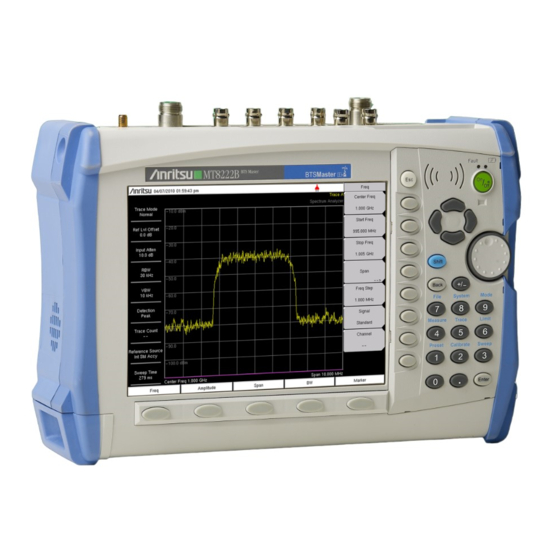
- Page 1 User Guide BTS Master MT8221B and MT8222B The High Performance Handheld Base Station Analyzer...
- Page 3 High Performance Handheld Base Station Analyzer Appendix A provides a list of supplemental documentation for the BTS Master features and options. The documentation set is available as PDF files on the documentation disc and the Anritsu Web site. Anritsu Company Part Number: 10580-00207...
- Page 5 LIMITATION OF WARRANTY The foregoing warranty does not apply to Anritsu connectors that have failed due to normal wear. Also, the warranty does not apply to defects resulting from improper or inadequate maintenance by the Buyer, unauthorized modification or misuse, or operation outside of the environmental specifications of the product.
- Page 7 This product and its manuals may require an Export License or approval by the government of the product country of origin for re-export from your country. Before you export this product or any of its manuals, please contact Anritsu Company to confirm whether or not these items are export-controlled.
- Page 9 Some or all of the following five symbols may or may not be used on all Anritsu equipment. In addition, there may be other labels attached to products that are not shown in the diagrams in this manual.
- Page 10 This equipment is supplied with a rechargeable battery that could potentially leak hazardous compounds into the environment. These hazardous compounds present a risk of injury or loss due to exposure. Anritsu Company recommends removing the battery for long-term storage of the instrument and storing the battery in a leak-proof, plastic container.
- Page 11 ESD Cautions ..........1-4 Anritsu Reference Documents ........1-4 Battery Replacement .
- Page 12 2-12 Symbols and Indicators........2-19 2-13 Firmware Overview .
- Page 13 Introduction ..........7-1 Anritsu Tool Box with Line Sweep Tools ......7-1 Install the Software .
- Page 14 Introduction ..........8-1 Master Software Tools Overview .
- Page 15 Throughout this manual, this instrument may be referred to as the BTS Master, or MT8221B/22B. Additional Documents This user guide is specific to the BTS Master MT8221B. Additional instrument functions and descriptions of optional measurement capabilities are described in measurement guides. Refer to Appendix A, “Measurement Guides”...
- Page 16 12 VDC source, which also simultaneously charges the battery. Anritsu Master Software Tools (MST), a PC-based software program, provides a convenient means for storing measurement data. Master Software Tools can also convert measurements from the BTS Master display into several graphic formats.
- Page 17 General Information 1-5 Preventive Maintenance Measurements may be stored in internal memory or in a USB Flash drive. Stored measurements can be downloaded to a PC by using the included USB and Ethernet cables. After being stored, a graphic trace can then be displayed, scaled, or enhanced in Master Software Tools with markers and limit lines.
- Page 18 The Cable and Antenna Analyzer requires calibration standards for OPEN, SHORT, and LOAD, which are sold separately. The Cable and Antenna Analyzer Measurement Guide is available on the documentation disc and the Anritsu web site. Refer to Appendix A, “Measurement Guides”, for a list of measurement guides and their...
- Page 19 Battery Compartment Door Note Use only Anritsu approved batteries, adapters, and chargers with this instrument. The battery that is supplied with the BTS Master may need charging before use. The battery can be charged while it is installed in the BTS Master by using either the AC-DC Adapter or the 12-Volt DC adapter, or separately in the optional Dual Battery Charger.
- Page 20 1-10 Soft Carrying Case General Information 1-10 Soft Carrying Case The instrument can be operated while in the soft carrying case. On the back of the case is a large storage pouch for accessories and supplies. To install the instrument into the soft carrying case: 1.
- Page 21 General Information 1-11 Tilt Bail Stand 1-11 Tilt Bail Stand The attached Tilt Bail can be used for desktop operation. The tilt bail provides a backward tilt for improved stability and air flow. To deploy the tilt bail, pull the bottom of the tilt bail away from the back of the instrument.
- Page 22 1-12 Secure Environment Workplace General Information 1-12 Secure Environment Workplace This section details the types of memory in the BTS Master, how to delete stored user files in internal memory, and recommended usage in a secure environment workplace. BTS Master Memory Types The instrument contains non-volatile disk-on-a-chip memory, EEPROM, and volatile DRAM memory.
- Page 23 General Information 1-12 Secure Environment Workplace Recommended Usage in a Secure Environment The BTS Master does not currently provide a secure erase feature. In environments where data security is an issue, it is recommended that users store their BTS Master created files on an external USB Flash drive that is then securely retained, sanitized, or destroyed after use.
- Page 24 1-12 Secure Environment Workplace General Information 1-10 PN: 10580-00207 Rev. E BTS Master UG...
- Page 25 Chapter 2 — Instrument Overview Introduction This chapter provides a brief overview of the Anritsu MT8221B BTS Master. The intent of this chapter is to acquaint you with the instrument. To begin using the instrument immediately, go to Chapter 3, “Basic Measurement Setups”, to find directions for power on,...
- Page 26 Instrument Overview Hardware Overview Turning On the MT8221B for the First Time The Anritsu MT8221B BTS Master is capable of approximately 2.5 hours of continuous operation from a fully charged, field-replaceable battery (refer to Section “Battery Replacement” on page 1-5 Chapter 1).
- Page 27 Instrument Overview 2-3 Front Panel Overview Front Panel Overview The BTS Master menu-driven interface is easy to use and requires little training. Hard keys on the front panel are used to initiate function-specific menus. Five main menu keys are located below the display. These keys vary in function depending upon the selected mode of instrument operation.
- Page 28 2-4 Front Panel Keys Instrument Overview Other features on the front panel include: Battery Charge LED (Green) The Battery Charge LED flashes if the battery is charging, and remains on steady when the battery is fully charged. Charge Fault LED (Red) The Charge Fault LED remains on steady under a battery charger fault condition.
- Page 29 Instrument Overview 2-4 Front Panel Keys Back Key Press this key to delete only one character, one number, or the range that is specified by the cursor. +/– Key Press this key to change the sign of numbers that are entered with the number keys. Number Keypad Press these keys to directly input numbers.
- Page 30 2-5 Mode Selector Menu Instrument Overview Mode Selector Menu To access the functions under the Mode menu, select the Shift key, then the Mode (9) key. Use the directional arrow keys or the rotary knob to highlight the selection, and press the Enter key to select.
- Page 31 Instrument Overview 2-6 Secondary Function Menus Secondary Function Menus Pressing the Shift key and then a number key selects the menu function that is printed in blue characters above the number key. Shift Secondary Menu Function “System (8)” Number Keypad Figure 2-5.
- Page 32 MT8221B display. For more detailed key descriptions of the Cable and Antenna Analyzer mode, refer to the Cable and Antenna Analyzer Measurement Guide (Anritsu part number 10580-00230, available on the documentation disc). Also refer to Appendix A, “Measurement...
- Page 33 Instrument Overview 2-7 Display Overview Real Time Display Battery Charge Submenu Key Clock Area Indicator Labels Instrument Settings Summary Main Menu Keys Figure 2-7. Spectrum Analyzer Display BTS Master UG PN: 10580-00207 Rev. E...
- Page 34 Control Measurement View Channels Results Figure 2-8. WCDMA/HSDPA Signal Analyzer CDP Display Overview For WCDMA/HSDPA information, refer to the 3GPP Measurement Guide available on the documentation disc and the Anritsu web site. 2-10 PN: 10580-00207 Rev. E BTS Master UG...
- Page 35 Instrument Overview 2-8 Parameter Setting Parameter Setting Pop-up list boxes or edit boxes are used to provide selection lists and selection editors. Scroll through a list of items or parameters with the arrow keys or the rotary knob. Select numerical values by scrolling with the arrow keys or rotary knob or by entering the digits directly from the number keypad.
- Page 36 2-9 Text Entry Instrument Overview Lowercase Text Entry Figure 2-9. Text Entry Menu – Lower Case Uppercase Text Entry Figure 2-10. Text Entry Menu – Upper Case 2-12 PN: 10580-00207 Rev. E BTS Master UG...
- Page 37 Instrument Overview 2-9 Text Entry Rotary Knob has scrolled to letter “c” Figure 2-11. Text Entry Menu – Selecting Characters BTS Master UG PN: 10580-00207 Rev. E 2-13...
- Page 38 2-10 Connector Care Instrument Overview 2-10 Connector Care Visually inspect connectors for general wear, for cleanliness, and for damage such as bent pins or connector rings. Repair or replace damaged connectors immediately. Dirty connectors can limit the accuracy of your measurements. Damaged connectors can damage the instrument.
- Page 39 Instrument Overview 2-11 Test Panel Connectors 2-11 Test Panel Connectors The test panel connectors are shown in Figure 2-12 Figure 2-13 and are described in the following text. IF Out 10 MHz Ref Out SPA RF In RF Output — Trigger In RF In VNA Port 2...
- Page 40 2-11 Test Panel Connectors Instrument Overview IF Out 10 MHz Ref Out SPA RF In RF Output — Trigger In RF In VNA Port 2 Headset Type-A External Antenna Jack Power T1, T3 Receive Mini-B Transmit Figure 2-13. Test Panel Connectors, Including T1 and T3 External Power The external power connector is used to power the unit and for battery charging.
- Page 41 Instrument Overview 2-11 Test Panel Connectors USB Interface – Type Mini-B The USB 2.0 interface can be used to connect the MT8221B BTS Master directly to a PC. The first time the MT8221B is connected to a PC, the normal USB device detection by the computer operating system will take place.
- Page 42 2-11 Test Panel Connectors Instrument Overview RF Output and VNA Port 1 RF output, 50 impedance, for reflection measurements. Max input is +23 dBm at 50 VDC. Ω ± To prevent damage to your instrument, do not use pliers or a plain wrench to tighten the Type-N connector.
- Page 43 Figure 2-2 on page 2-3) flashes when the battery is charging, and remains on steady when the battery is fully charged. Caution Use only Anritsu-approved batteries, adapters, and chargers with this instrument. BTS Master UG PN: 10580-00207 Rev. E 2-19...
- Page 44 2-13 Firmware Overview Instrument Overview The battery symbol is replaced by a red plug body to indicate that the instrument is running from external power and is not charging the battery (or to indicate that the battery is not present). When the external AC adaptor is connected, the battery automatically receives a charge, and the battery symbol with the lightning bolt is displayed (Figure 2-15).
- Page 45 Instrument Overview 2-13 Firmware Overview Table 2-1. Mode-Dependent Main Menu Keys Located Below Measurement display Mode Key 1 Key 2 Key 3 Key 4 Key 5 Fixed WiMAX Freq Amplitude Setup Measurements Mobile WiMAX Freq Amplitude Setup Measurements Marker T1/FT1, E1, T3/T1/FT1 Configuration Pattern/Loop Error/Alarm Measurements...
- Page 46 2-13 Firmware Overview Instrument Overview 2-22 PN: 10580-00207 Rev. E BTS Master UG...
- Page 47 Setups Introduction This chapter provides a brief overview of the Anritsu MT8221B BTS Master. The intent of this chapter is to provide a starting point for making basic measurement setups. This chapter describes setup, configure frequency, bandwidth, and amplitude before configuring your measurement setups.
- Page 48 3-3 Set the Measurement Frequency Basic Measurement Setups Set the Measurement Frequency Using Start and Stop Frequencies 1. Press the Freq main menu key. In Cable & Antenna Analyzer mode, press the Freq/Dist main menu key. 2. Press the Start Freq submenu key. 3.
- Page 49 Basic Measurement Setups 3-4 Set the Amplitude Set the Amplitude Press the Amplitude main menu key to display the Amplitude menu. Setting Amplitude Reference Level and Scale Spectrum Analyzer and Interference Analysis Modes To change the current measurement units, press the Units submenu key and Note select the required units from the submenu keys that are presented.
- Page 50 3-5 Set the Span Basic Measurement Setups Power Offset Set Up for Compensating External Loss To obtain accurate results, compensate for any external attenuation by using power offset. In power offset mode, the compensation factor is in dB. (External attenuation can be created by using an external cable or an external high power attenuator.) Press the Power Offset submenu key and use the keypad, the arrow keys, or the rotary knob to enter the desired offset value.
- Page 51 Basic Measurement Setups 3-6 Setting Up Limit Lines Setting Up Limit Lines Press the Shift key then the Limit (6) key on the numeric keypad to display the Limit menu. Single Limit Line Spectrum Analyzer and Interference Analysis Modes 1. Press the Limit (Upper / Lower) submenu key to select the desired limit line, Upper or Lower.
- Page 52 3-6 Setting Up Limit Lines Basic Measurement Setups 12. Press the Frequency submenu key and enter 2000 MHz. 13. Press the Amplitude submenu key and enter 15 dB. Cable and Antenna Mode 1. Press the Shift key followed by the Limit main menu key to list the Limit menu. 2.
- Page 53 Basic Measurement Setups 3-7 Setting Up Markers Setting Up Markers Press the Marker main menu key to display the Marker menu. Selecting, Activating, and Placing a Marker 1. Press the Marker 1 2 3 4 5 6 submenu key so that the desired marker number is underlined.
- Page 54 PN: 10580-00207 Rev. E BTS Master UG...
- Page 55 Chapter 4 — File Management Introduction This chapter will review the file management features of the BTS Master and detail the File menu. The submenus under this menu allow the user to save, recall, copy, and delete files in internal memory or an external USB flash drive. Managing Files Press the Shift key then the File (7) key on the numeric keypad to list the File menu.
- Page 56 4-2 Managing Files File Management Recall Files The recall menu enables you to view all the Measurement and Setup files in the internal memory and external USB flash drive. You can sort the recall menu by name, date, or type. You can also select to view only measurement files or setup files by pressing File Type on the Recall dialog box and selecting the file type you want to view.
- Page 57 File Management 4-2 Managing Files Copying Files The steps below detail copying a file from internal memory to an external flash drive. Select the files to copy in the top window and the location for the files to be copied to in the bottom window (Figure 4-2).
- Page 58 4-2 Managing Files File Management Deleting Files Delete a Selected File or Files Press the Delete submenu key. Highlight the file to be deleted with the Up/Down arrow keys. Press the Select or De-Select key. The file will be highlighted in blue when selected. Press the Delete key and Enter to delete the selected file.
- Page 59 File Management 4-3 File Menu Overview File Menu Overview Open this menu by pressing the Shift key, then the File (7) key. File Save Measurement As FileName.spa Save Save Measurement a b c d e f Save g h i Spectrum Save j k l...
- Page 60 4-7. Measurement Measurements can be saved to internal memory or to a USB flash drive. The BTS Master is shipped with an Anritsu-approved USB flash drive for external Recall Recall data storage. (Refer to the BTS Master Technical Data Sheet listed in Appendix A for the Anritsu Part Number of the USB flash drive).
- Page 61 File Management 4-4 File Menu Save Menu Key Sequence: File > Save Text Entry Keys: The top 5 keys are for text entry. The submenu keys for Save Text Entry displays the characters (alphabet, hyphen, and underscore). Press the submenu key (for example) to open another submenu a b c / d e f a b c with a separate key for each of these letters.
- Page 62 4-4 File Menu File Management Save Location Menu Key Sequence: File > Save > Change Save Location This menu and dialog box is used to create folders and select where the Save Location BTS Master will save the current file. Select folders or drives with the Up/Down keys or the rotary knob.
- Page 63 File Management 4-4 File Menu Save On Event Menu Key Sequence: File > Save On Event This menu is used to auto save measurements to internal memory after: Save On..Crossing Limit: Toggling this submenu key to On will save the ...Crossing Limit measurement to internal memory when the measurement has crossed a defined limit line created with the Limit menu.
- Page 64 4-4 File Menu File Management Recall Menu Key Sequence: File > Recall This menu and dialog box is used to create folders and select where the Recall BTS Master will save the current file. Select folders or drives with the Up/Down keys or the rotary knob.
- Page 65 File Management 4-4 File Menu Copy Menu Key Sequence: File > Copy This menu and dialog box is used to copy folders and files. Select folders or Copy files with the Up/Down keys or the rotary knob. Figure 4-2 on page 4-3 shows the Copy dialog box with two Jpeg images and one folder (including Sort By the folder’s contents) selected and ready to be copied to the USB flash...
- Page 66 4-4 File Menu File Management Delete Menu Key Sequence: File > Delete This menu and dialog box is used to delete folders and files. Select folders Delete or files with the Up/Down keys or the rotary knob. Sort By Sort By: Press this submenu key to sort files and folders by name, by the type of file, or by the date that the file or folder was saved.
- Page 67 Chapter 5 — System Operation Introduction This chapter will review the BTS Master system operations. • “System Menu Overview” on page 5-2 • “System Menu” on page 5-3 • “Preset Menu” on page 5-7 • “Self Test” on page 5-7 •...
- Page 68 5-2 System Menu Overview System Operation System Menu Overview To access the functions under the System menu, select the Shift key, then the System (8) key. Menu maps typically display all possible submenu keys, although some keys are displayed on the instrument only under special circumstances (refer to menu descriptions).
- Page 69 The display lists a summary of those tests that have passed. If any test fails, Application then all of the performed tests are listed with Pass/Fail notification. If any test fails, then contact your Anritsu Service Center and report the test results Options (refer to “Contacting Anritsu”...
- Page 70 5-3 System Menu System Operation System Options Menu Key Sequence: Shift, System (8) > System Options Date & Time: Press this submenu key to display a dialog box for setting the System Options current date and time. Use the submenu keys or the Left/Right arrow keys to select the field to be modified.
- Page 71 System Operation 5-3 System Menu System Options 2/2 Menu Key Sequence: Shift, System (8) > System Options > More Share CF & Pwr Offset All Modes Not Shared: Press this submenu key to toggle the setting to System Options 2/2 All Modes or to Not Shared.
- Page 72 Esc rather than pressing Enter. Master Note: This same reset sequence can be initiated when turning the BTS Master On by pressing and holding the Esc+On keys until the Anritsu Reset splash screen is displayed.
- Page 73 If the BTS Master is within the specified operating range with a charged battery, and the self test fails, then contact your Anritsu Service Center. To initiate a self test when the system is already powered up: 1.
- Page 74 5-6 Update Firmware System Operation Update Firmware Using a USB Memory Device The BTS Master contains a feature that allows you to update its firmware by using a USB memory device. First, you must load the USB memory device with the firmware using Master Software Tools (MST).
- Page 75 System Operation 5-6 Update Firmware Figure 5-9. Firmware Update Menu 5. Highlight each of the save choices: Save None, Save User Data, and Save & Restore User Data. Read through each choice carefully and then select the desired save mode. •...
- Page 76 7. The Firmware Update dialog will query you to confirm the process by pressing Enter to continue or Esc to abort (Figure 5-10). Figure 5-10. Firmware Update Menu 8. Select Enter and the firmware update process begins and the Firmware Update dialog displays the following message Updating firmware.
- Page 77 Chapter 6 — GPS (Option 31) Introduction This chapter provides a brief overview of the Anritsu MT8221B BTS Master. The intent of this chapter is to acquaint you with the instrument. To begin using the instrument immediately, go to Chapter “Basic Measurement Setups”...
- Page 78 6-2 Setting Up GPS (Option 31) GPS (Option 31) Setting Up GPS (Option 31) The MT8221B BTS Master is available with a built-in GPS receiver (Option 31) that can provide latitude, longitude, altitude, and UTC timing information. This option also enhances frequency reference oscillator accuracy.
- Page 79 GPS (Option 31) 6-2 Setting Up GPS (Option 31) When the GPS receiver is tracking at least 3 satellites, the GPS icon changes to green. Figure 6-2. GPS Icon, Green As long as 3 minutes may be required for the Ref Freq status to change to GPS High Accuracy in the Status menu, which is displayed on the left side of the measurement display.
- Page 80 6-3 GPS Menu GPS (Option 31) GPS Menu Key Sequence: Shift, System (8) > GPS GPS: Press this submenu key to turn GPS on or off. GPS Info: Press this submenu key to display the current GPS information. GPS Voltage 3.3 V 5 V: Press this submenu key to set the source voltage to be either 3.3 V or 5 V depending on the GPS receiver being used.
- Page 81 Start and navigate through the Programs folder to the Anritsu folder. Then click on the Anritsu Tool Box shortcut to open the Anritsu Tool Box. Once the Tool Box is open, move the mouse pointer over any of the application icons to view a short description of the application.
- Page 82 Anritsu easyMap Tools software. If this software had already been installed on your computer, the Tool Box will link to it. If not, clicking on the icons will bring you to the Anritsu web site, where you will be able to download the software free of charge.
- Page 83 Figure 7-3. Line Sweep Tools Window Line Sweep Tools can open DAT files from HHST; or VNA/DAT files from Anritsu’s E-series instruments. It also can open PIM files. Either way, the file once opened, can be inspected and modified in many different ways. Line Sweep Tools saves files as a new type of DAT file, and can export traces as VNA, text, JPG, BMP, or PNG.
- Page 84 7-6 Using Line Sweep Tools Anritsu Tool Box and Line Sweep Tools Markers and Limit Lines The easiest way to manage markers is to turn one on and use the mouse to drag it to the desired position. The marker tool bar is shown in Figure 7-4.
- Page 85 Anritsu Tool Box and Line Sweep Tools 7-6 Using Line Sweep Tools Renaming Grid The renaming grid, much like the naming grid in the E series instruments, allows users to quickly and consistently rename filenames, trace titles, and trace subtitles. The grid can be set up with custom phrases to make the renaming process simpler.
- Page 86 7-6 Using Line Sweep Tools Anritsu Tool Box and Line Sweep Tools Report Generator To use the report generator in Line Sweep Tools, go to File menu and select Report Setup to tell Line Sweep Tools how you want the report to appear. In this case, the report will have the...
- Page 87 Anritsu Tool Box and Line Sweep Tools 7-6 Using Line Sweep Tools Once the report generator is setup, File > Generate Report, will create the PDF. The report will include all traces that were open at the time the report was made (Figure 7-8).
- Page 88 PN: 10580-00207 Rev. E BTS Master UG...
- Page 89 “Updating Instrument Firmware” on page 8-2 Master Software Tools Overview Anritsu Master Software Tools is a Microsoft Windows 2000 and Windows XP compatible program for transferring and editing saved measurements, markers, and limit lines to a PC. Master Software Tools will not function on earlier versions of the Microsoft Windows operating system.
- Page 90 8-5 Updating Instrument Firmware Master Software Tools Installing MST MST is provided on the CD-ROM included with the instrument. Insert the CD-ROM into a PC to run the installer. Follow the onscreen instruction. Updating Instrument Firmware 1. Connect the BTS Master to a PC by using USB or Ethernet. Refer to the Master Software Tools (MST) User Guide (on the CD-ROM) for information regarding connecting your BTS Master to a PC.
- Page 91 8-4, the status of the highlighted file is Available, and the Install to Unit button is gray and inactive. This means that the updated file is on the Anritsu Product Support Web site and needs to be downloaded to your PC. After the file has been downloaded and placed on your PC, its status changes to Ready, and the Install to Unit button becomes active.
- Page 92 8-5 Updating Instrument Firmware Master Software Tools Figure 8-4. Product Updates Window: Status Available File Status Ready: 1. Check that the file status is Ready and that the Install to Unit button is active. 2. Click the Install to Unit button. Your BTS Master is updated with the new firmware. File Status Available: 1.
- Page 93 1. Click the Check for Updates button. Master Software Tools checks for the latest updates at the Anritsu Product Support Web Site. New updates that are found are listed in the file menu. 2. Click the Retrieve File button. The file is transferred from the Web site to your PC.
- Page 94 8-5 Updating Instrument Firmware Master Software Tools PN: 10580-00207 Rev. E BTS Master UG...
- Page 95 Master Software Tools 8-5 Updating Instrument Firmware BTS Master UG PN: 10580-00207 Rev. E...
- Page 96 8-5 Updating Instrument Firmware Master Software Tools PN: 10580-00207 Rev. E BTS Master UG...
- Page 97 Master Software Tools 8-5 Updating Instrument Firmware BTS Master UG PN: 10580-00207 Rev. E...
- Page 98 8-5 Updating Instrument Firmware Master Software Tools 8-10 PN: 10580-00207 Rev. E BTS Master UG...
- Page 99 This appendix provides a list of supplemental documentation for BTS Master features and options. These measurement guides are available as PDF files on the documentation disc and the Anritsu web site for download. Table A-1. Analyzer Options (Sheet 1 of 2)
- Page 100 IEEE 802.16 Mobile WiMAX Over-the-Air Signal Analyzer (0037) T1 Analyzer (0051) E1 Analyzer (0052) T3/T1 Analyzer (0053) Backhaul Analyzer BTS Master MT8221B/22B with Option 450, Comms Board Measurement Guide (10580-00238) T1 Analyzer (0055) E1 Analyzer (0054) OC-3C Signal Analyzer (0058)
- Page 101 Factory Defaults, ESC+ON, or MASTER RESET, System+ON. Caution: Use of MASTER RESET, System+ON, will erase all user saved setups and measurement traces and return the unit to a fully Factory Default condition. If the error persists, contact your Anritsu Service Center.
- Page 102 Factory Defaults, ESC+ON, or MASTER RESET, System+ON. Caution: Use of MASTER RESET, System+ON, will erase all user saved setups and measurement traces and return the unit to a fully Factory Default condition. If the error persists, contact your Anritsu Service Center.
- Page 103 Use of MASTER RESET, System+ON, will erase all user saved setups and measurement traces and return the unit to a fully Factory Default condition. If the error persists, contact your Anritsu Service Center. BTS Master UG PN: 10580-00207 Rev. E...
- Page 104 MASTER RESET, System+ON. Caution: Use of MASTER RESET, System+ON, will erase all user saved setups and measurement traces and return the unit to a fully Factory Default condition. If the error persists, contact your Anritsu Service Center. PN: 10580-00207 Rev. E...
- Page 105 Defaults, ESC+ON, or MASTER RESET, System+ON. Caution: Use of MASTER RESET, System+ON, will erase all user saved setups and measurement traces and return the unit to a fully Factory Default condition. If the error persists, contact your Anritsu Service Center. IF Cal is OFF Factory Calibration is OFF.
- Page 106 Factory Defaults, ESC+ON. Caution: Use of MASTER RESET, System+ON, will erase all user saved setups and measurement traces and return the unit to a fully Factory Default condition. If the error persists, contact your Anritsu Service Center. Copy failed. Please check External USB Memory Attempt to copy user saved data to the external USB Flash drive has failed.
- Page 107 Appendix C — LAN and DHCP Introduction This appendix describes network connections for the MT8221B BTS Master. Ethernet Configuration LAN Connection The RJ-45 connector is used to connect the BTS Master to a local area network. Integrated into this connector are two LEDs. The amber LED shows the presence of a 10 Mbit/s LAN connection when on, and a 100 Mbit/s LAN connection when off.
- Page 108 C-2 Ethernet Configuration LAN and DHCP To display the IP address with the instrument on, press the Shift key, then the System (8) key, then the soft key and the soft key. The IP address will be System Options Ethernet Config displayed as shown in Figure C-1.
- Page 109 LAN and DHCP C-2 Ethernet Configuration Ethernet Config Press this submenu key to display the Ethernet submenu and to open the Ethernet Editor dialog box in order to set the IP address of the instrument. Figure C-2. Setting IP Address Manually BTS Master UG PN: 10580-00207 Rev.
- Page 110 C-2 Ethernet Configuration LAN and DHCP Ethernet Menu Key Sequence: Shift, System (8) > System Options > Ethernet Config Type Ethernet Manual DHCP: Press this submenu key to select whether the address will be entered manually, or will be supplied automatically by a network DHCP Type server.
- Page 111 LAN and DHCP C-3 DHCP DHCP DHCP stands for Dynamic Host Configuration Protocol. It is a protocol that allows a server to dynamically assign IP addresses to devices that are connected to the network. Most networks include a DHCP server to manage IP addresses. When a DHCP server is available on the network, DHCP is the preferred IP address assignment mode.
- Page 112 Windows 2000 IP Configuration Ethernet adapter Local Area Connection: Connection-specific DNS Suffix. : us.anritsu.com IP Address... . : 172.26.202.172 Subnet Mask ... : 255.255.252.0 Default Gateway .
- Page 113 LAN and DHCP C-5 Ping Tool Ping Tool Another tool that can find out if a selected IP address is already on the network is ping. Ping is a harmless way to determine if an address is found on the network, and (if it is found) to receive a reply.
- Page 114 PN: 10580-00207 Rev. E BTS Master UG...
- Page 115 LAN connection ....C-1 Anritsu, contact ....1-1 more information ....C-5 antenna documents, reference .
- Page 116 ....2-20 setting up markers ... . . 3-7 http, contacting Anritsu ... . 1-1 menu copy .
- Page 117 ..... . . 4-7 URL contacting Anritsu ... . 1-1 SCPI commands, not with password .
- Page 118 Index-4 PN: 10580-00207 Rev. E BTS Master UG...
- Page 120 Anritsu Company 490 Jarvis Drive Anritsu utilizes recycled paper and environmentally conscious inks and toner. Morgan Hill, CA 95037-2809 http://www.anritsu.com...
- Page 121 Measurement Guide 3GPP Signal Analyzer for Anritsu RF and Microwave Handheld Instruments BTS Master™, Cell Master™, Spectrum Master™, LMR Master™ Demod GSM/GPRS/EDGE Option 40 Option 41 W-CDMA/HSPA+ Option 44 Option 65 Option 35 TD-SCDMA/HSPA+ Option 60 Option 61 Option 38...
- Page 122 BTS Master, Cell Master, LMR Master, and Spectrum Master are trademarks of Anritsu Company. Notice Anritsu Company has prepared this manual for use by Anritsu Company personnel and customers as a guide for the proper installation, operation and maintenance of Anritsu Company equipment and computer programs.
- Page 123 Contacting Anritsu ........
- Page 124 Table of Contents (Continued) 2-17 Limit Menu ..........2-17 2-18 Other Menus .
- Page 125 Table of Contents (Continued) 3-11 Setup Menu ..........3-28 Setup 1/2 Menu .
- Page 126 Table of Contents (Continued) TD-SCDMA/HSPA+ Menus ........4-13 Freq (Frequency) Menu .
- Page 127 Table of Contents (Continued) LTE Over-the-Air (OTA) Measurements ......5-16 Antenna Status ......... . 5-16 Scanner .
- Page 128 Table of Contents (Continued) 5-19 Other Menus ..........5-47 Chapter 6—TD-LTE Signal Analyzer Introduction .
- Page 129 Anritsu easyMap Tools ........
- Page 130 Table of Contents (Continued) Coverage Mapping Menu ........7-12 Mapping Save/Recall Menu.
- Page 131 Chapter 1 — General Information Introduction This Measurement Guide documents 3GPP signal analysis for the following Anritsu instruments: • BTS Master • Cell Master • Spectrum Master • LMR Master Not all instrument models offer every option. Please refer to the Technical Data...
- Page 132 1-2 3GPP Signal Analysis Overview General Information TD-SCDMA/HSPA+ TD-SCDMA/HSPA+ signal analysis is described in Chapter 4, “TD-SCDMA/HSPA+ Signal Analyzer”. • Option 882: TD-SCDMA/HSPA+ Measurements (requires Option 9) • Option 60*: TD-SCDMA/HSPA+ RF Measurements • Option 61*: TD-SCDMA/HSPA+ Demodulation • Option 38*: TD-SCDMA/HSPA+ OTA Measurements LTE signal analysis is described in Chapter 5, “LTE Signal Analyzer”.
- Page 133 General Information 1-3 Selecting a Measurement Mode Selecting a Measurement Mode To change the measurement mode, press Shift, then the Mode (9) button to open the Mode Selector list box. Highlight the desired measurement mode using the Up or Down arrow keys or the rotary knob and press Enter.
- Page 134 On this page you can find links to sales, service, and support contact information for your country or region. You can also provide online feedback, complete a “Talk to Anritsu” form to have your questions answered, or obtain other services offered by Anritsu.
- Page 135 Chapter 2 — GSM/GPRS/EDGE Signal Analyzer Introduction The Global Systems for Mobile (GSM) communication is a globally accepted standard for digital cellular communication. GSM uses a combination of Frequency Division Multiple Access (FDMA) and Time Division Multiple Access (TDMA). Within each band are approximately one hundred available carrier frequencies on 200 kHz spacing (FDMA), and each carrier is broken up into time-slots so as to support eight separate conversations (TDMA).
- Page 136 2-2 Measurement Setup GSM/GPRS/EDGE Signal Analyzer Measurement Setup Please refer to the instrument User Guide for detailed information on how to select the GSM/GPRS/EDGE Signal Analyzer mode, set up the frequency range, amplitude, limit lines, markers, and file management. GSM/GPRS/EDGE RF Measurements GSM RF measurements consists of Spectrum, Power versus Time (frame), Power versus Time (slot), Summary and Demodulator.
- Page 137 GSM/GPRS/EDGE Signal Analyzer 2-4 Measurement Display Figure 2-1. GSM Single Channel Measurement Figure 2-2. GSM Multi-Channel Measurement 3GPP MG PN: 10580-00234 Rev. V...
- Page 138 2-4 Measurement Display GSM/GPRS/EDGE Signal Analyzer To display Power versus Time (Frame) press the Power versus Time (Frame) submenu key to activate the Power versus Time (Frame) measurement (Figure 2-3). Figure 2-3. GSM Power vs. Time (Frame) Measurement To display Power versus Time (Slot) press the Power versus Time (Slot) submenu key to activate the Power versus Time (Slot) measurement (Figure 2-4).
- Page 139 GSM/GPRS/EDGE Signal Analyzer 2-5 Demodulator Demodulator This measurement demodulates the GSM/GPRS/EDGE signal and displays the vector with Phase Error, EVM, Origin Offset, C/I, Modulation Type and Magnitude Error (as applicable). Figure 2-5 Figure 2-6. To demodulate the GSM/EDGE signal: 1. Set the frequency as described in the User Guide. 2.
- Page 140 2-5 Demodulator GSM/GPRS/EDGE Signal Analyzer Figure 2-6. EDGE Demodulator Measurement To display the GSM/EDGE Summary screen (Figure 2-7), press the GSM/EDGE Summary soft key. Figure 2-7. GSM/EDGE Summary PN: 10580-00234 Rev. V 3GPP MG...
- Page 141 GSM/GPRS/EDGE Signal Analyzer 2-6 GSM/GPRS/EDGE Mode Pass/Fail GSM/GPRS/EDGE Mode Pass/Fail The unit can store test sets for testing base station performance and can recall these test sets for quick, easy measurements. These test sets are for reference only and can be edited using Master Software Tools.
- Page 142 2-7 Measurement Results GSM/GPRS/EDGE Signal Analyzer Measurement Results Average Burst Power The average burst power over 10 measured burst power values. This average is restarted when a new frequency is selected. Channel Power Channel power measures the average power in a GSM/EDGE frame in the frequency specified.
- Page 143 GSM/GPRS/EDGE Signal Analyzer 2-7 Measurement Results Carrier to Interference Ratio – C/I (dB) Carrier to Interference Ratio is the ratio of the desired carrier power to the undesired signal power (interferer) in dB. This value is an estimate that is derived from the measured RMS EVM value.
- Page 144 2-8 GSM/GPRS/EDGE Menus GSM/GPRS/EDGE Signal Analyzer GSM/GPRS/EDGE Menus Figure 2-9 show the map of GSM/GPRS/EDGE menus. The following sections describe GSM/GPRS/EDGE main menus and associated submenus. The submenus are listed in the order they appear on the display from top to bottom under each main menu. Frequency Amplitude Setup...
- Page 145 GSM/GPRS/EDGE Signal Analyzer 2-9 Freq (Frequency) Menu Freq (Frequency) Menu Key Sequence: Freq Center Freq: Press the Freq key followed by the Center Freq submenu key Frequency and enter the desired frequency using the keypad, the arrow keys, or the rotary knob.
- Page 146 2-10 Amplitude Menu GSM/GPRS/EDGE Signal Analyzer 2-10 Amplitude Menu Key Sequence: Amplitude Power Offset: Enter the power offset to automatically adjust for the loss or Amplitude gain through any external cables, attenuators and couplers. The power can be offset from 0 dB to 100 dB in either direction. Press the Power Offset key, Power Offset then enter a value using the arrow keys, rotary knob, or numeric keypad.
- Page 147 GSM/GPRS/EDGE Signal Analyzer 2-12 Measurements Menu 2-12 Measurements Menu Key Sequence: Measurements Spectrum: Opens the “Spectrum Menu” on page 2-14. Measurements Power versus Time (Frame): Displays approximately eight and a half slots of the GSM/EDGE signal frame starting from the first active slot found. The Spectrum screen also displays Channel Power, Occupied Bandwidth, Frequency Error in PPM and Hz, Modulation Type, Burst Power, Avg Burst Power, and BSIC.
- Page 148 2-12 Measurements Menu GSM/GPRS/EDGE Signal Analyzer Spectrum Menu Key Sequence: Measurements > Spectrum Channel Spectrum: Displays the spectrum of the selected channel. The Spectrum screen also displays Channel Power, Occupied Bandwidth, Frequency Error in PPM and Hz, Burst and Average Burst Power, and the Base Channel Station Identity Code (BSIC).
- Page 149 GSM/GPRS/EDGE Signal Analyzer 2-12 Measurements Menu Demodulator Menu Key Sequence: Measurements > Demodulator I/Q View: Allows selection between Vector or Const. Demodulator Back: Returns to the “Measurements Menu”. I/Q View Vector Const Back Figure 2-15. GSM/GPRS/EDGE Freq Menu 3GPP MG PN: 10580-00234 Rev.
- Page 150 2-12 Measurements Menu GSM/GPRS/EDGE Signal Analyzer Pass/Fail Mode Menu Key Sequence: Measurements > Pass/Fail Mode Select Pass/Fail Test: Display the available test sets in the Select Pass/Fail Mode Pass/Fail Test window. Select Reset: Resets the Pass/Fail Mode test. Pass/Fail ScriptMaster: Opens the Select File by Scrolling window and also lists Test Recall and Back submenu keys.
- Page 151 GSM/GPRS/EDGE Signal Analyzer 2-13 Marker Menu 2-13 Marker Menu Key Sequence: Marker This menu is available only in Multi-Channel Spectrum view and opens the MC Spectrum submenu. See the “Spectrum Menu” on page 2-14 for details. 2-14 Sweep Menu Key Sequence: Shift > Sweep (3) key Sweep Single/Continuous: This submenu key toggles between Sweep continuous sweep and single sweep.
- Page 152 2-18 Other Menus GSM/GPRS/EDGE Signal Analyzer 2-18 PN: 10580-00234 Rev. V 3GPP MG...
- Page 153 Chapter 3 — W-CDMA/HSPA+ Signal Analyzer Introduction The WCDMA/HSPA+ signal analyzer supports the following measurement modes: • RF Measurements • Demodulator • Over-The-Air (OTA) Measurements Connect the instrument to any Node B/BTS for accurate RF and demodulator measurements. The W-CDMA/HSPA+ Demodulator option demodulates both W-CDMA and Note HSPA+ signals.
- Page 154 3-2 W-CDMA/HSPA+ Measurements W-CDMA/HSPA+ Signal Analyzer W-CDMA/HSPA+ Measurements Use an applicable band pass filter to eliminate out of band signals that can cause Note mixer saturation. Carrier Frequency Carrier Frequency is the selected transmitter operating center frequency entered by the user or calculated from the signal standard and channel number entered by the user.
- Page 155 W-CDMA/HSPA+ Signal Analyzer 3-2 W-CDMA/HSPA+ Measurements Channel Power Channel power is the total power transmitted in the 5 MHz W-CDMA channel specified. Channel Power measures the node B/base station transmitting power across the entire 5 MHz W-CDMA (BTS) channel. Channel power is displayed in dBm and Watts. For Over the Air (OTA) measurements, the channel power will vary as the signal path from the node B transmitter to the instrument varies.
- Page 156 3-2 W-CDMA/HSPA+ Measurements W-CDMA/HSPA+ Signal Analyzer Peak to Average Power Peak to Average power is the ratio of the peak power and the RMS power of the signal calculated over one frame interval and is displayed in dB. Peak CD Error (Peak Code Domain Error) PCDE takes the noise and projects the maximum impact it will have on all OVSF codes.
- Page 157 W-CDMA/HSPA+ Signal Analyzer 3-3 General Measurement Setups General Measurement Setups Please refer to the User Guide for information on selecting the W-CDMA/HSPA+ Signal Analyzer mode, setting up frequency, amplitude, power offset for compensating external loss, limit lines, markers, and file management. Scrambling Code Setup The scrambling code can be set up automatically or manually.
- Page 158 3-3 General Measurement Setups W-CDMA/HSPA+ Signal Analyzer Threshold Setup The threshold level is an advanced setting that can be set to indicate which codes are considered active. In the Code Domain Power screen, the threshold level is indicated by a horizontal dotted red line.
- Page 159 W-CDMA/HSPA+ Signal Analyzer 3-4 W-CDMA/HSPA+ RF Measurements W-CDMA/HSPA+ RF Measurements The W-CDMA/HSPA+ RF Measurements consist of three measurements: • Spectrum • Adjacent Channel Leakage Ratio (ACLR) • Spectral Emission Mask To make W-CDMA RF measurements, connect the RF in connector to the node B equipment. Screen captured images are provided as examples.
- Page 160 3-4 W-CDMA/HSPA+ RF Measurements W-CDMA/HSPA+ Signal Analyzer 4. Move the cursor, using the directional arrow keys or the rotary knob, to select the desired channel. The Channel Number can also be directly entered using the numerical keypad. Figure 3-1. Band Spectrum Channel Spectrum Setup The channel spectrum screen displays the selected channel signal and the following measurements: channel power in dBm and Watts, occupied bandwidth, and peak to average...
- Page 161 W-CDMA/HSPA+ Signal Analyzer 3-4 W-CDMA/HSPA+ RF Measurements Figure 3-2. Channel Spectrum ACLR Measurement Setup ACLR (Adjacent Channel Leakage Ratio) is defined as the ratio of the amount of leakage power in an adjacent channel to the total transmitted power in the main channel and is displayed in table format under the bar graph.
- Page 162 3-4 W-CDMA/HSPA+ RF Measurements W-CDMA/HSPA+ Signal Analyzer 3. Press the RF Measurements submenu key. The ACLR measurement uses the filtered channel power to determine the ACLR Note values and it is listed as filtered on the display. In all other screens the unfiltered channel power is displayed as channel power.
- Page 163 W-CDMA/HSPA+ Signal Analyzer 3-4 W-CDMA/HSPA+ RF Measurements ACLR Multi-channel ACLR Procedure 1. Press the Measurements main menu key. 2. Press the RF Measurements submenu key. 3. Press the ACLR submenu key to activate the ACLR measurement. 4. Press the ACLR submenu key again to open the ACLR menu. 5.
- Page 164 3-4 W-CDMA/HSPA+ RF Measurements W-CDMA/HSPA+ Signal Analyzer Spectral Emission Mask Procedure 1. Set the measurement frequency using one of the methods listed in the User Guide. 2. Press the Measurements main menu key. 3. Press the RF Measurements submenu key. 4.
- Page 165 W-CDMA/HSPA+ Signal Analyzer 3-4 W-CDMA/HSPA+ RF Measurements 5. Press the Spectral Emission Summary submenu key to display the Spectral Emission Summary table (Figure 3-6). Figure 3-6. Spectral Emission Mask Summary RF Summary The RF Summary displays the critical transmitter performance measurements in the table format, without demodulating the W-CDMA/HSPA+ signal.
- Page 166 3-5 Demodulator W-CDMA/HSPA+ Signal Analyzer Figure 3-7. RF Summary Demodulator In the demodulator mode, the RF In is connected to the node B equipment and the unit will demodulate the W-CDMA signal. The W-CDMA/HSPA+ demodulator has Code Domain Power (CDP), HSPDA, Codogram and Modulation Summary screens. The W-CDMA/HSPA+ Demodulator option demodulates both W-CDMA and Note HSPA+ signals.
- Page 167 W-CDMA/HSPA+ Signal Analyzer 3-5 Demodulator Code Domain Power (CDP) Procedure 1. Set the measurement frequency using one of the methods listed in the User Guide. 2. Press the Setup main menu key. 3. Press the Scrambling Code submenu key to select Auto so that the scrambling code is automatically detected.
- Page 168 3-5 Demodulator W-CDMA/HSPA+ Signal Analyzer Figure 3-8. CDP Measurement Summary Activating Markers 1. Press the Marker main menu key to display the Marker menu. 2. Press the Marker submenu key to select the appropriate marker (1 through 6). The underlined marker number is the currently selected marker. 3.
- Page 169 W-CDMA/HSPA+ Signal Analyzer 3-5 Demodulator HSPA+ Setup HSPA+ displays the spreading factor (OVSF codes) 256 or 512 codes and high speed downlink physical shared channel codes HS-PDSCH. The right or left active codes can be selected using the cursor. The selected code power versus time and constellation are displayed. The demodulator also displays CPICH, P-CCPCH, S-CCPCH, PICH, P-SCH and S-SCH power in the table format.
- Page 170 3-5 Demodulator W-CDMA/HSPA+ Signal Analyzer 6. Press the IQ Persistence submenu key and use the keypad or rotary knob to set the IQ Persistence to 2. The instrument will display the constellation diagram after the first sample, and then update the constellation diagram after the second sample. IQ Persistence can be set as high as 48.
- Page 171 W-CDMA/HSPA+ Signal Analyzer 3-5 Demodulator 10. Press the Codogram submenu key to activate the Codogram measurement. 11. Press the Codogram submenu key again to list the Codogram menu and set the zoom and test time parameters for the measurement. 12. Press the Zoom submenu key to select the appropriate zoom level. The Zoom key toggles between 32, 64, and 128.
- Page 172 3-6 Over-the-Air Measurements W-CDMA/HSPA+ Signal Analyzer Over-the-Air Measurements OTA Setup In Over-the-Air (OTA) mode, the instrument is not connected to the node B equipment. The OTA screen displays the six strongest scrambling codes as bar graphs. Displayed underneath the bar graphs are the related scrambling code number, CPICH, Ec/Io, Ec, and pilot dominance in the table format.
- Page 173 W-CDMA/HSPA+ Signal Analyzer 3-6 Over-the-Air Measurements Figure 3-11. OTA Measurement Summary 3GPP MG PN: 10580-00234 Rev. V 3-21...
- Page 174 3-6 Over-the-Air Measurements W-CDMA/HSPA+ Signal Analyzer W-CDMA Summary Setup W-CDMA summary (Figure 3-12) displays the critical W-CDMA measurements from RF and demodulation measurements. Figure 3-12. W-CDMA Measurement Summary W-CDMA Summary Procedure 1. Set the measurement frequency using one of the methods listed in the User Guide. 2.
- Page 175 W-CDMA/HSPA+ Signal Analyzer 3-7 Pass/Fail Mode Setup 10. Press the Measurements main menu key. 11. Press the W-CDMA Summary submenu key. Pass/Fail Mode Setup The instrument stores the five test models specified in the 3GPP specification (TS 125.141) for testing base station performance and recalls these models for quick easy measurements. After selection of a test model, the instrument displays test results in tabular format with clear PASS or FAIL indications that include min/max threshold.
- Page 176 3-8 W-CDMA/HSPA+ Menus W-CDMA/HSPA+ Signal Analyzer W-CDMA/HSPA+ Menus Figure 3-14 show the map of the W-CDMA/HSPA+ menus. The following sections describe W-CDMA/HSPA+ main menus and associated submenus. The submenus are listed in the order they appear on the display from top to bottom under each main menu. Frequency Amplitude Setup 1/2...
- Page 177 W-CDMA/HSPA+ Signal Analyzer 3-8 W-CDMA/HSPA+ Menus Demodulator Zoom Table Zoom Start HSDPA HSDPA Selected Code # Control Channels Delta Codogram Codogram Next Active Zoom Code Modulation Left Summary Next Active Zoom Start Code Back Right Total Time Total Time 240 s 240 s Back Single Sweep Time...
- Page 178 3-9 Freq (Frequency) Menu W-CDMA/HSPA+ Signal Analyzer Freq (Frequency) Menu Key Sequence: Freq Center Freq: Press the Freq key followed by the Center Freq submenu key Freq and enter the desired frequency using the keypad, the arrow keys, or the rotary knob.
- Page 179 W-CDMA/HSPA+ Signal Analyzer 3-10 Amplitude Menu 3-10 Amplitude Menu Key Sequence: Amplitude Scale: The scale can be set in 1 dB steps from 1 dB per division to 15 dB Amplitude per division. The value can be changed using the numeric keypad, rotary knob, or the arrow keys.
- Page 180 3-11 Setup Menu W-CDMA/HSPA+ Signal Analyzer 3-11 Setup Menu Setup 1/2 Menu Key Sequence: Setup Setup 1/2 Scrambling Code Scrambling Code: Press the Scrambling Code submenu key to toggle Auto Manual between Auto and Manual Scrambling Code. Manual Scrambling Code: Press the Manual Scrambling Code submenu Manual Scrambling key to manually enter the scrambling code using the arrow keys, rotary knob, Code...
- Page 181 W-CDMA/HSPA+ Signal Analyzer 3-11 Setup Menu Setup 2/2 Menu Key Sequence: Setup > More Setup 2/2 Threshold Threshold: Sets the measurement threshold to be set either automatically by the instrument or manually by the user. Auto Manual Manual Threshold: Change the measurement threshold manually by Manual Threshold entering a desired value and pressing Enter.
- Page 182 3-12 Measurements Menu W-CDMA/HSPA+ Signal Analyzer 3-12 Measurements Menu Key Sequence: Measurements RF Measurement: Opens the “RF Measurement Menu” on page 3-31. Measurements Demodulator: Opens the “Demodulator Menu” on page 3-34. In this mode, the received W-CDMA signal is demodulated. The demodulator has five RF Measurements displays, CDP, CDP Table, HSPA+, Codogram and Modulation Summary.
- Page 183 W-CDMA/HSPA+ Signal Analyzer 3-12 Measurements Menu RF Measurement Menu Key Sequence: Measurements > RF Measurements Band Spectrum: Opens the “Band Spectrum Menu” on page 3-32. RF Measurements Channel Spectrum: Opens the “Channel Spectrum Menu” on page 3-32. Band Press once to select the Channel Spectrum display. The screen also displays Channel Power in dBm and watts, Peak to Average power and Spectrum Occupied Bandwidth.
- Page 184 3-12 Measurements Menu W-CDMA/HSPA+ Signal Analyzer Band Spectrum Menu Key Sequence: Measurements > RF Measurements > Band Spectrum Ref Level: Sets the required reference level. Band Spectrum Scale: Changes the scale. Ref Level Band Channel: Use the cursor to select the required channel to analyze the selected channel signal.
- Page 185 W-CDMA/HSPA+ Signal Analyzer 3-12 Measurements Menu ACLR Menu Key Sequence: Measurements > RF Measurements > ACLR Display Trace: Select On to display the trace. ACLR Select # of Main Channels: Set the main channels from 1 channel to 4 Display Trace channels.
- Page 186 3-12 Measurements Menu W-CDMA/HSPA+ Signal Analyzer Demodulator Menu Key Sequence: Measurements > Demodulator CDP: Open the “CDP Menu” on page 3-35. When Code Domain Power Demodulator (CDP) is selected the screen displays all the selected OVSF codes and selected OVSF zoom codes in the graphical format. The display also displays P-CPICH Abs power, EVM, Carrier Frequency, Channel Power, Carrier Feedthrough, Frequency Error in Hz and PPM, Noise Floor and Peak CD Error.
- Page 187 W-CDMA/HSPA+ Signal Analyzer 3-12 Measurements Menu CDP Menu Key Sequence: Measurements > Demodulator > CDP Zoom: Select a zoom function of 32, 64, or 128 codes. Zoom Start: Enter the required zoom start code. For example, to start at Zoom code 2, enter 2.
- Page 188 3-12 Measurements Menu W-CDMA/HSPA+ Signal Analyzer HSDPA Menu Key Sequence: Measurements > Demodulator > HSDPA Selected Code: Press this submenu key to select the active code, using the HSDPA arrow keys, rotary knob, or numeric keypad. The range is 0 to 255 or 0 to 511 depending on the Max Spreading Factor set under the Setup main menu.
- Page 189 W-CDMA/HSPA+ Signal Analyzer 3-12 Measurements Menu Codogram Menu Key Sequence: Measurements > Demodulator > Codogram Zoom: Select a zoom function of 32, 64, or 128 codes. Codogram Zoom Start: Enter the required zoom start code. For example, to start at Zoom code 2, enter 2.
- Page 190 3-12 Measurements Menu W-CDMA/HSPA+ Signal Analyzer Over-The-Air Menu Key Sequence: Measurements > OTA Scrambling Code: Opens the “OTA Setup Menu” on page 3-39. Over-The-Air Multipath: Opens the “Multipath Menu” on page 3-40. EMF (Option 444 only): When first selected, this submenu key enables the Scrambling Code EMF Measurement mode.
- Page 191 W-CDMA/HSPA+ Signal Analyzer 3-12 Measurements Menu OTA Setup Menu Key Sequence: Measurements > OTA > Scrambling Code Scrambling Code: Set the scrambling codes to manual or auto. OTA Setup Manual Code: Select the scrambling code manually. Scrambling Code On/Off: Switch On/Off the manually selected scrambling code. Manual Auto Code Lock: Lock the measured codes.
- Page 192 3-12 Measurements Menu W-CDMA/HSPA+ Signal Analyzer Multipath Menu Key Sequence: Measurements > OTA > Multipath Scrambling Code: Set the scrambling codes to manual or auto. Multipath Manual Scrambling Code: Sets the manual scrambling code. Scrambling Code Vert Display: Switch vertical display between RSCP and Rel Pwr. Auto Manual Horiz Display: Switch between Chips and uSec for the horizontal display.
- Page 193 W-CDMA/HSPA+ Signal Analyzer 3-12 Measurements Menu Pass/Fail Mode Menu Key Sequence: Measurements > Pass/Fail Mode Select Pass/Fail Test: Select the parameters file from the list. Pass/Fail Mode Reset: Restart the measurement. Select ScriptMaster: Opens the “ScriptMaster Menu” on page 3-41. Pass/Fail Test Back: Returns to the...
- Page 194 3-13 Marker Menu W-CDMA/HSPA+ Signal Analyzer 3-13 Marker Menu Key Sequence: Marker Press the Marker main menu key to open the Marker menu. The instrument is equipped with six markers. Any or all markers can be employed simultaneously. Marker: Selects the active marker (1 to 6). The underlined marker number Marker is the active marker.
- Page 195 W-CDMA/HSPA+ Signal Analyzer 3-15 Measure Menu 3-15 Measure Menu This menu is not available in W-CDMA/HSPA+ measurement mode. 3-16 Trace Menu This menu is not available in W-CDMA/HSPA+ measurement mode. 3-17 Limit Menu This menu is not available in W-CDMA/HSPA+ measurement mode. 3-18 Other Menus Preset, File, Mode and System are described in the instrument User Guide.
- Page 196 3-18 Other Menus W-CDMA/HSPA+ Signal Analyzer 3-44 PN: 10580-00234 Rev. V 3GPP MG...
- Page 197 Chapter 4 — TD-SCDMA/HSPA+ Signal Analyzer Introduction The TD-SCDMA/HSPA+ Signal Analyzer offers three options: • RF Measurements • Demodulator • Over-The-Air (OTA) Measurements Three display types are provided for RF Measurements: Channel Spectrum display, Power versus Time display, or the RF Summary table. Demodulator measurements can be viewed in either the CDP Data display or the Modulation Summary table.
- Page 198 4-3 TD-SCDMA/HSPA+ RF Measurements TD-SCDMA/HSPA+ Signal Analyzer UpPTS Pwr The power in the Uplink Pilot Slot, excluding the gap. DL-UL Delta Power The average difference between the active DL slots and the active UL slots, including pilot slots. UL and DL slots are selected according to the Uplink Switch Point setting. Without UL data slot and without UpPTS, the DL-UL Delta Power value is not applicable.
- Page 199 TD-SCDMA/HSPA+ Signal Analyzer 4-3 TD-SCDMA/HSPA+ RF Measurements Channel Spectrum Figure 4-1. TD-SCDMA/HSPA+ Channel Spectrum 1. Press the Setup main menu key. 2. Press the More submenu key. a. Press the Number of Carriers submenu key so that the desired number is underlined.
- Page 200 4-3 TD-SCDMA/HSPA+ RF Measurements TD-SCDMA/HSPA+ Signal Analyzer Power versus Time The Power versus Time view shows the time domain view. 1. Press the Setup main menu key. a. Press the Slot Selection submenu key. The Slot Selection window and menu open. In the list window, use the rotary knob or press the touch screen to highlight Auto or the desired slot (0 to 6), then press the Enter key.
- Page 201 TD-SCDMA/HSPA+ Signal Analyzer 4-3 TD-SCDMA/HSPA+ RF Measurements Figure 4-2. TD-SCDMA/HSPA+ Power vs. Time: Sub-Frame Measurement Figure 4-3. TD-SCDMA/HSPA+ Power vs. Time: Slot Measurement 3GPP MG PN: 10580-00234 Rev. V...
- Page 202 4-3 TD-SCDMA/HSPA+ RF Measurements TD-SCDMA/HSPA+ Signal Analyzer RF Summary The RF Summary displays the critical RF transmitter performance measurements in a table format, without demodulating the TD-SCDMA/HSPA+ signal. The parameters that are displayed in the RF summary table are Channel Power (dBm), Channel Power (RRC) (dBm), Occupied Bandwidth (Hz), DwPTS Power (dBm), UpPTS Power (dBm), On/Off Ratio (dB), Slot PAR (dB), Left Channel Power (dBm), Right Channel Power (dBm), Left Channel Occupied Bandwidth, and Right Channel Occupied Bandwidth.
- Page 203 TD-SCDMA/HSPA+ Signal Analyzer 4-4 TD-SCDMA/HSPA+ Demodulator TD-SCDMA/HSPA+ Demodulator Figure 4-4. TD-SCDMA/HSPA+ Demodulator, CDP Data The following parameters are measured in the Demodulator option. Slot Power The power measured in the selected slot, excluding the gap. If Slot Selection is set to Auto, then the instrument searches for an active downlink slot and uses the detected slot number for measuring slot power.
- Page 204 4-4 TD-SCDMA/HSPA+ Demodulator TD-SCDMA/HSPA+ Signal Analyzer Scrambling Codes The display format is Scrambling Code # (relative power in dB). A measure of the relative powers of the four scrambling codes (relative to Slot Power) that correspond to the detected SYNC-DL code. Only those scrambling codes with high relative power are displayed. Typically, only one scrambling code is displayed unless significant interference occurs from neighboring codes.
- Page 205 TD-SCDMA/HSPA+ Signal Analyzer 4-4 TD-SCDMA/HSPA+ Demodulator g. Press the Meas Speed submenu key to toggle through the measuring speeds: Fast, Norm, and Slow. h. Press More to continue with setups in the Advanced Settings menu. Refer to “Advanced Settings Menu” on page 4-20 for a description of available parameters.
- Page 206 4-5 TD-SCDMA/HSPA+ Over-the-Air Measurements TD-SCDMA/HSPA+ Signal Analyzer TD-SCDMA/HSPA+ Over-the-Air Measurements Figure 4-5. TD-SCDMA/HSPA+ OTA Code Scan Code Scan Scans and displays the power of all 32 SYNC-DL codes in sequential order, including Ec/Io (dB) and Tau (µs). DwPTS Power and Pilot Dominance values are displayed below the table of codes (see Figure 4-5).
- Page 207 TD-SCDMA/HSPA+ Signal Analyzer 4-5 TD-SCDMA/HSPA+ Over-the-Air Measurements Figure 4-6. TD-SCDMA/HSPA+ OTA Tau Scan Measurement Setup Refer to the User Guide for selecting the TD-SCDMA/HSPA+ Signal Analyzer mode. 1. Press the Setup main menu key. Press the Trigger submenu key. The Trigger menu opens.
- Page 208 4-6 TD-SCDMA/HSPA+ Pass/Fail Measurements TD-SCDMA/HSPA+ Signal Analyzer TD-SCDMA/HSPA+ Pass/Fail Measurements The following is an example of a Pass/Fail measurement. Measurement Setup Refer to the User Guide for selecting the TD-SCDMA/HSPA+ Signal Analyzer mode. 1. Press the Measurements main menu key. 2.
- Page 209 TD-SCDMA/HSPA+ Signal Analyzer 4-7 TD-SCDMA/HSPA+ Menus TD-SCDMA/HSPA+ Menus Freq Amplitude Setup Measurements Center Freq Scale / div Slot Selection RF Measurements 871.400 MHz 10 dB/div Signal Power Offset Trigger Demodulator Standard 0.0 dB Ext Loss Channel Auto Range Uplink Switch Point 4357 Set CF Adjust...
- Page 210 4-7 TD-SCDMA/HSPA+ Menus TD-SCDMA/HSPA+ Signal Analyzer Advanced Settings RF Measurements Number of Carriers Channel Spectrum Spreading Factor Power vs. Time Auto Power vs. Time Modulation Type View Auto Sub-Frame Slot DwPTS Spectrum Emission Slot Selection Auto Slot Selection Tau Offset Mask Auto 0 ms...
- Page 211 TD-SCDMA/HSPA+ Signal Analyzer 4-8 Freq (Frequency) Menu Freq (Frequency) Menu Key Sequence: Freq Center Freq: Press this submenu key to set the receiver center frequency to Freq the desired value. Enter the frequency (2.7 GHz is the maximum value that can be entered) by using the keypad, the arrow keys, or the rotary knob.
- Page 212 4-9 Amplitude Menu TD-SCDMA/HSPA+ Signal Analyzer Amplitude Menu Key Sequence: Amplitude Scale/div: Press this submenu key to change the scale of the y-axis in the Amplitude measurement display. The range of the scale can be set from 1 dB/div to 15 dB/div in steps of 1 dB/div.
- Page 213 TD-SCDMA/HSPA+ Signal Analyzer 4-10 Setup Menu 4-10 Setup Menu Key Sequence: Setup Slot Selection: Press this submenu key to display the “Slot Selection Menu” Setup on page 4-18 and open the Slot Selection window. Use the rotary knob or press the touch screen to highlight the desired slot (0 to 6), then press Enter. If Auto is selected, the active slot is automatically detected.
- Page 214 4-10 Setup Menu TD-SCDMA/HSPA+ Signal Analyzer Slot Selection Menu Key Sequence: Setup > Slot Selection Auto: Automatically looks for an active downlink slot. Auto in the Slot Slot Selection Selection window and the Auto submenu key have the same function. The Auto submenu key provides a one-touch method of selecting the Auto setting.
- Page 215 TD-SCDMA/HSPA+ Signal Analyzer 4-10 Setup Menu SYNC-DL Code Menu Key Sequence: Setup > SYNC-DL Code Auto: Automatically seeks the active SYNC-DL code. Auto in the SYNC-DL SYNC-DL Code Code selection window and the Auto submenu key have the same function. The Auto submenu key provides a one-touch method of selecting the Auto Auto setting.
- Page 216 4-10 Setup Menu TD-SCDMA/HSPA+ Signal Analyzer Advanced Settings Menu Key Sequence: Setup > More Number of Carriers: Press this submenu key to select the number of Advanced Settings carriers present in the signal. The setting toggles between 1 and 3. Number of Carriers Spreading Factor: Select the desired spreading factor, Auto, 16 or 1.
- Page 217 TD-SCDMA/HSPA+ Signal Analyzer 4-11 Measurements Menu 4-11 Measurements Menu Key Sequence: Measurements RF Measurements: Press this submenu key to display the Measurements “RF Measurements Menu” on page 4-22. Demodulator: Press this submenu key to display the “Demodulator Menu” RF Measurements on page 4-24 and to set up demodulator testing.
- Page 218 4-11 Measurements Menu TD-SCDMA/HSPA+ Signal Analyzer RF Measurements Menu Key Sequence: Measurements > RF Measurements Channel Spectrum: Displays the spectrum of the input signal. The span is RF Measurements automatically set to 5 MHz. Beneath the graph, values for the following measurements are displayed: Left Channel Power, Channel Power, Right Channel Channel Power, Left Channel Occ BW, Occ BW, and Right Channel Occ...
- Page 219 TD-SCDMA/HSPA+ Signal Analyzer 4-11 Measurements Menu Power vs. Time Menu Key Sequence: Measurements > RF Measurements > Power vs. Time Power vs. Time View: Press this submenu key to display the Power vs. Time graph in View either the Sub-Frame view or the Slot view. Slot Selection: Press this submenu key to display the Slot Selection Sub-Frame Slot...
- Page 220 4-11 Measurements Menu TD-SCDMA/HSPA+ Signal Analyzer Demodulator Menu Key Sequence: Measurements > Demodulator CDP Data: Press this submenu key once to activate this test. Press this Demodulator submenu key again to display the CDP Data menu and further set up the measurement.
- Page 221 TD-SCDMA/HSPA+ Signal Analyzer 4-11 Measurements Menu Over-The-Air Menu Key Sequence: Measurements > OTA Code Scan: Press this submenu key to display the 32 sync codes in table Over-The-Air format. Displayed below the table are DwPTS Power (in dBm) and Pilot Dominance (in dB).
- Page 222 4-11 Measurements Menu TD-SCDMA/HSPA+ Signal Analyzer Pass Fail Mode Menu Key Sequence: Measurements > Pass Fail Mode Select Pass/Fail Test: Press this submenu key to open the Select Pass/Fail Pass/Fail Mode Test selection window. Use the rotary knob or the arrow keys, or press the touch screen to highlight the desired test (PASS_FAIL_RF, Select PASS_FAIL_DEMOD, or PASS_FAIL_ALL), then press the Select Test...
- Page 223 TD-SCDMA/HSPA+ Signal Analyzer 4-12 Sweep Menu 4-12 Sweep Menu Key Sequence: Shift > Sweep (3) key Sweep Hold/Run: Press this submenu key to toggle between Run mode Sweep and Hold mode. Hold mode prevents the instrument from taking any new measurements and freezes the current measurement.
- Page 224 4-16 Other Menus TD-SCDMA/HSPA+ Signal Analyzer 4-28 PN: 10580-00234 Rev. V 3GPP MG...
- Page 225 Chapter 5 — LTE Signal Analyzer Introduction The Long Term Evolution (LTE) Signal Analyzer offers three measurement options: • RF Measurements The following display types are provided for RF measurements: Channel Spectrum display, ACLR display, Spectral Emission Mask display, and the RF Summary table. •...
- Page 226 5-2 General Measurement Setups LTE Signal Analyzer 4. Press Sync then the Sync Type submenu key to select between the Normal (SS) or RS for synchronization. RS should be selected ONLY when there is no sync signal. This happens only when directly connected to a base station that is configured such that one of the antenna ports does not have a sync signal.
- Page 227 LTE Signal Analyzer 5-3 LTE RF Measurements LTE RF Measurements The following parameters are measured in the RF Measurement mode. Channel Spectrum Channel Spectrum displays the spectrum of the input signal across one channel. The Channel Power and Occupied BW are computed and displayed below the graph. Channel Power Channel power measures the average power within the selected bandwidth and is expressed in dBm or Watts.
- Page 228 5-3 LTE RF Measurements LTE Signal Analyzer RF Measurement Setups Channel Spectrum 1. Press the Measurements main menu key. 2. Press the RF submenu key. 3. Press the Channel Spectrum submenu key to activate this RF measurement view (Figure 5-2). 4.
- Page 229 LTE Signal Analyzer 5-3 LTE RF Measurements ACLR 1. Press the Measurements main menu key. 2. Press the RF submenu key. 3. Press the ACLR submenu key to activate ACLR display and measurement (Figure 5-3). Figure 5-3. Adjacent Channel Leakage Ratio 4.
- Page 230 5-3 LTE RF Measurements LTE Signal Analyzer Spectral Emission Mask 1. Press the Measurements main menu key. 2. Press the RF submenu key. 3. Press the Spectral Emission Mask submenu key to activate the Spectral Emission measurement and display (Figure 5-4).
- Page 231 LTE Signal Analyzer 5-3 LTE RF Measurements RF Summary 1. Press the Measurements main menu key. 2. Press the RF submenu key. 3. Press the RF Summary submenu key to activate and display the RF measurements in table format (Figure 5-5).
- Page 232 5-4 LTE Modulation Measurements LTE Signal Analyzer LTE Modulation Measurements The following parameters are measured in the Modulation Measurement mode. Power vs Resource Block (RB) This measurement displays the Power vs RB grid, an RB Color Map, the measurements table, and measurement progress bar.
- Page 233 LTE Signal Analyzer 5-4 LTE Modulation Measurements Markers Markers are available for use in the Power vs Resource Block measurement. The markers will outline the selected RB. Above the two dimensional grid, the specific RB subcarrier/sub-frame coordinates will be displayed along with its power level. Constellation This measurement displays the constellation of the demodulated symbols over the first sub-frame and a results table of the measurements described below.
- Page 234 5-4 LTE Modulation Measurements LTE Signal Analyzer Control Channel Power This measurement shows the power levels of key physical layer Control Channels and also includes the numerical results table described in the “Constellation” section above. EVM per control channel is also available (see Figure 5-8 on page 5-13), as well as a table view showing the power in both per-resource-element and total power formats.
- Page 235 LTE Signal Analyzer 5-4 LTE Modulation Measurements Modulation Measurement Setups Power vs Resource Block 1. Press the Measurements main menu key. 2. Press the Modulation submenu key. 3. Press the Power vs Resource Block submenu key to activate the Power vs Resource Block measurement view.
- Page 236 5-4 LTE Modulation Measurements LTE Signal Analyzer Markers 1. While in the Power vs Resource Block measurement, press the Marker main menu key. The RB Marker submenu opens. The Marker State button default value is On, so the markers highlight a row of sub-frames and a column of sub-carriers. 2.
- Page 237 LTE Signal Analyzer 5-4 LTE Modulation Measurements Control Channel Power 1. Press the Measurements main menu key. 2. Press the Modulation submenu key. 3. Press the Control Channel Power submenu key to activate the Control Channel Power display (Figure 5-8). Press the key again to view or change the Display Mode and Control Channel EVM settings.
- Page 238 5-4 LTE Modulation Measurements LTE Signal Analyzer Tx Time Alignment 1. Press the Measurements main menu key. 2. Press the Modulation submenu key. 3. Press the Tx Time Alignment submenu key to set the modulation measurement to Tx Time Alignment view. The instrument display lists the Time Alignment measurement results and the TAE values for each antenna pair.
- Page 239 LTE Signal Analyzer 5-4 LTE Modulation Measurements Modulation Summary 1. Press the Measurements main menu key. 2. Press the Modulation submenu key. 3. Press the Modulation Summary submenu key to activate and display the modulation measurements in table format (Figure 5-11).
- Page 240 5-5 LTE Over-the-Air (OTA) Measurements LTE Signal Analyzer LTE Over-the-Air (OTA) Measurements Scanner, Tx Test, Mapping, and Carrier Aggregation are measurements taken over the air. EMF measurements are available only with Option 444. Antenna Status The Antenna Status indicators, if any, are located in the bottom left corner of the instrument display.
- Page 241 TX antennas to two RX antennas on the same frequency and time, but different reference signals. Your Anritsu test instrument supports 2x2 and 4x4 MIMO configurations. Note that 4x4 MIMO may not be available if your instrument is loaded with older firmware. Refer to your instrument User Guide for instructions on updating firmware.
- Page 242 5-5 LTE Over-the-Air (OTA) Measurements LTE Signal Analyzer Sync Signal (SS) Power Sync signal power is displayed in dBm or Watts. EVM (rms) The RMS (%) of all the error vectors, between the reconstructed ideal signals and the received signals, divided by the RMS value of the ideal signals. EVM (pk) The peak (%) of all the error vectors, between the reconstructed ideal signals and the received signals, divided by the RMS value of the ideal signals.
- Page 243 LTE Signal Analyzer 5-5 LTE Over-the-Air (OTA) Measurements b. Press the Show Mod Results submenu key to display or hide the Modulation Results of the strongest signal. When Show Mod Results is on, the scanner measurement speed is slower due to Note the additional time required to demodulate the strongest signal.
- Page 244 5-5 LTE Over-the-Air (OTA) Measurements LTE Signal Analyzer 5. Press Back to return to the Over-the-Air menu. When Show Mod Results is on, the Tx Test measurement speed is slower due to Note the additional time required to demodulate the strongest signal. Some instruments require the LTE demod option to toggle this submenu to On.
- Page 245 LTE Signal Analyzer 5-5 LTE Over-the-Air (OTA) Measurements Carrier Aggregation 1. Press the Measurements main menu key. 2. Press the Over-the-Air submenu key. 3. Press the Carrier Aggregation submenu key to display the OTA Carrier Aggregation table. Press the key again to display the Carrier Aggregation menu. See Figure 5-14.
- Page 246 5-6 Pass/Fail Tests LTE Signal Analyzer Pass/Fail Tests 1. Press the Measurements main menu key. 2. Press the Pass/Fail Test submenu key to activate the Pass/Fail display in table format (Figure 5-15). Press the Pass/Fail Test submenu key again to select a Pass/Fail test. a.
- Page 247 LTE Signal Analyzer 5-7 LTE Summary LTE Summary The following parameters are displayed in the LTE Summary measurement. Freq Error Frequency error is the difference between the received center frequency and the specified center frequency. This value is linked to the external frequency reference accuracy and is typically useful only with a good external frequency reference or GPS reference.
- Page 248 5-7 LTE Summary LTE Signal Analyzer Measurement Setup 1. Press the Measurements main menu key. 2. Press the LTE Summary submenu key to activate and display the LTE measurements in table format. Figure 5-16. LTE Summary 5-24 PN: 10580-00234 Rev. V 3GPP MG...
- Page 249 LTE Signal Analyzer 5-8 LTE Menus LTE Menus in Power vs. RB Measurement Freq Amplitude Setup Measurements Marker Marker Center Freq Scale Marker Select Marker State 1.000 GHz 10 dB/div 10 MHz Power Offset Cyclic Prefix Marker State Marker RB # Signal Standard Modulation 0.0 dB Ext Loss...
- Page 250 5-8 LTE Menus LTE Signal Analyzer LTE Menus (continued) Modulation Pass/Fail Test Power vs Select Power vs RB Pass/Fail Resource Block Test Autoscale Color Map Constellation Reset Constellation RB Color Map Reference Points Max Value Control Channel 0.0 dBm Control Channels Power RB Color Map Display Mode...
- Page 251 LTE Signal Analyzer 5-8 LTE Menus LTE Menus (continued) Carrier Aggregation Center Freq 1.000 GHz Signal Standard Channel Set CF To Closest Channel 10 MHz Back Back Figure 5-19. LTE Menu Layout (3 of 3) 3GPP MG PN: 10580-00234 Rev. V 5-27...
- Page 252 5-9 Freq (Frequency) Menu LTE Signal Analyzer Freq (Frequency) Menu Key Sequence: Freq Center Freq: Press this submenu key to set the receiver center frequency to Freq the desired value. Enter the frequency by using the keypad, the arrow keys, or the rotary knob.
- Page 253 LTE Signal Analyzer 5-9 Freq (Frequency) Menu Standard List Menu Key Sequence: Freq > Signal Standard Display: Toggles between displaying all available signal standards and the Standard List signal standards marked as favorites (* in the Fav column). Display Select/Deselect Favorite: Press this submenu key to select or deselect a signal standards as a favorite.
- Page 254 5-10 Amplitude Menu LTE Signal Analyzer 5-10 Amplitude Menu Key Sequence: Amplitude Scale: Press this submenu key to change the scale of the y-axis in the Amplitude RF measurement displays. The range of the scale can be set from 1 dB/div to 15 dB/div in steps of 1 dB/div.
- Page 255 LTE Signal Analyzer 5-11 Setup Menu 5-11 Setup Menu Key Sequence: Setup BW: Opens the Select Bandwidth list. Choose from the available Setup bandwidths. Cyclic Prefix: Press this key to set the instrument to measure signal with a Normal or Extended Cyclic Prefix, or to allow the instrument to detect 10 MHz the Cyclic Prefix automatically.
- Page 256 5-12 Measurements Menu LTE Signal Analyzer 5-12 Measurements Menu Key Sequence: Measurements RF: Press this submenu key to display the “RF Menu” on page 5-33. Measurements Modulation: Press this submenu key to display the “Modulation Menu” on page 5-34. Over-the-Air: Press this submenu key to display the “Over-the-Air Menu”...
- Page 257 LTE Signal Analyzer 5-12 Measurements Menu RF Menu Key Sequence: Measurements > RF Channel Spectrum: Displays the spectrum of the input signal. Beneath the graph, values for the following measurements are displayed: Channel Power Channel and Occupied BW. Channel Power is displayed in dBm or Watts (based on the Units submenu setting in the Amplitude menu) and Occupied BW is Spectrum displayed in MHz.
- Page 258 5-12 Measurements Menu LTE Signal Analyzer Modulation Menu Key Sequence: Measurements > Modulation Power vs Resource Block: Press once to display the Power vs. Resource Modulation Block measurement window. Press again to open the “Power vs. Resource Block Menu” on page 5-35 for setting up the Resource Block Color Map Power vs parameters.
- Page 259 LTE Signal Analyzer 5-12 Measurements Menu Power vs. Resource Block Menu Key Sequence: Measurements > Modulation > Power vs. Resource Block Autoscale Color Map: Adjusts the RB Max Value and Range automatically Power vs RB on the color map. RB Color Map Max Value: Press to adjust the RB Color Map Max Value Autoscale Color Map manually.
- Page 260 5-12 Measurements Menu LTE Signal Analyzer Constellation Menu Key Sequence: Measurements > Modulation > Constellation Reference Points: Press this submenu key to display reference points Constellation (small white circles) for the various constellations. On is the default state. Reference Points Data Legend: Turns the legend box in the top right corner of the constellation graph On and Off.
- Page 261 LTE Signal Analyzer 5-12 Measurements Menu Control Channel Power Menu Key Sequence: Measurements > Modulation > Control Channel Power Display Mode: Select Bar Graph or Table as the desired view. Control Channels Control Channel EVM On Off: When On, the EVM column is included to Display Mode display the EVM of each control channel.
- Page 262 5-12 Measurements Menu LTE Signal Analyzer Over-the-Air Menu Key Sequence: Measurements > Over-the-Air Scanner: Press this submenu key to display the Scanner table, which Over-the-Air shows several power measurements for multiple base stations at the same frequency. Measurements include Sync Signal (S-SS) Power, RSRP, RSRQ, and SINR.
- Page 263 LTE Signal Analyzer 5-12 Measurements Menu OTA Scanner Menu Key Sequence: Measurements > Over-the-Air > Scanner > Scanner Sort By: Opens the Sort By list dialog. Choose one of the following OTA Scanner parameters to sort the Scanner table rows. Sort By Cell ID Group ID...
- Page 264 5-12 Measurements Menu LTE Signal Analyzer Over-the-Air Tx Test Menu Key Sequence: Measurements > Over-the-Air > Tx Test Show Mod Results: When set to Off, the PBCH Results table and OTA Tx Test Antenna Status indicators are not displayed. When set to On, the Antenna Status and PBCH Modulation Results table are displayed.
- Page 265 LTE Signal Analyzer 5-12 Measurements Menu Coverage Mapping Menu Key Sequence: Measurements > Over-the-Air > Mapping Save/Recall Map Points: Opens the “Mapping Save/Recall Menu” Coverage Mapping on page 7-13. Measurement Setups: Opens the “Measurement Setup Menu” on page 7-14. Point Distance/Time Setup: Opens the “Point Distance/Time Setup Menu”...
- Page 266 5-12 Measurements Menu LTE Signal Analyzer Carrier Aggregation Menu Key Sequence: Measurements > Over-the-Air > Carrier Aggregation CC1 through CC5: Select the desired Component Carrier to set up for measurement. See Figure 5-36. Carrier Aggregation Note: When switching from the Carrier Aggregation to other measurements, the frequency is automatically set to the currently selected Component Carrier, if it is on.
- Page 267 LTE Signal Analyzer 5-12 Measurements Menu Component Carrier Menu Key Sequence: Measurements > Over-the-Air > Carrier Aggregation > CC1 CC1 Off On: Turns On the Component Carrier. Center Freq: Press this submenu key to set the receiver center frequency. Enter the frequency using the keypad, arrow keys, or the rotary knob. When entering a frequency using the keypad, the submenu key labels change to Units: GHz, MHz, kHz, and Hz.
- Page 268 5-12 Measurements Menu LTE Signal Analyzer Pass/Fail Test Menu Key Sequence: Measurements > Pass/Fail Test > Select Pass/Fail Test Select Pass/Fail Test: Press this submenu key to open the Select Pass/Fail Pass/Fail Test Test list box and select a test type. Choose from: Select PASS_FAIL_RF Pass/Fail...
- Page 269 LTE Signal Analyzer 5-13 Marker Menu 5-13 Marker Menu Key Sequence: Marker Available for Channel Spectrum measurements. When making Power vs Resource Block measurements, refer to “Power vs Resource Block Marker Menu” on page 5-46. Marker Select: Selects the active marker M1 or M2. The underlined marker Marker is active marker.
- Page 270 5-14 Calibrate Menu LTE Signal Analyzer Power vs Resource Block Marker Menu Key Sequence: Marker (When Power vs. Resource Block measurement is selected). Marker Select: Selects the active marker M1 or M2. The underlined marker Marker is active marker. Each press of the submenu key moves the underline to the other marker.
- Page 271 LTE Signal Analyzer 5-17 Trace Menu 5-17 Trace Menu This menu is not available in LTE measurement mode. 5-18 Limit Menu This menu is not available in LTE measurement mode. 5-19 Other Menus Preset, File, Mode and System are described in the instrument User Guide. 3GPP MG PN: 10580-00234 Rev.
- Page 272 5-19 Other Menus LTE Signal Analyzer 5-48 PN: 10580-00234 Rev. V 3GPP MG...
- Page 273 Chapter 6 — TD-LTE Signal Analyzer Introduction The Time-Division Long Term Evolution (TD-LTE) Signal Analyzer offers three measurement options: • RF Measurements The following display types are provided for RF measurements: Channel Spectrum display, Power vs. Time, ACLR display, Spectral Emission Mask display, and the RF Summary table.
- Page 274 6-3 TD-LTE RF Measurements TD-LTE Signal Analyzer Antenna Status The Antenna Status indicator can show when antennas are detected and which one is currently being measured. Antenna Status is displayed for any EVM measurement shown: Constellation, Control Channel Power, Modulation Summary and LTE Summary. The antennas icons are displayed at the lower-left corner of the display screen (Figure 6-1).
- Page 275 TD-LTE Signal Analyzer 6-3 TD-LTE RF Measurements Cell ID Identifying information sent by the transmitter in the sync signal. Timing Error The error in time between the external trigger input signal and the start of the frame. The Timing Error is only displayed if Triggering is set up to use an external trigger signal to act as a timing reference.
- Page 276 6-3 TD-LTE RF Measurements TD-LTE Signal Analyzer RF Measurement Setups Channel Spectrum 1. Press the Measurements main menu key. 2. Press the RF submenu key. 3. Press the Channel Spectrum submenu key to activate this RF measurement view (Figure 6-2). 4.
- Page 277 TD-LTE Signal Analyzer 6-3 TD-LTE RF Measurements Power vs. Time 1. Press the Measurements main menu key. 2. Press the RF submenu key. 3. Press the Power vs. Time submenu key to select measurement. 4. Press the Power vs. Time submenu key again to set the View and Sub-Frame Number parameters.
- Page 278 6-3 TD-LTE RF Measurements TD-LTE Signal Analyzer ACLR 1. Press the Measurements main menu key. 2. Press the RF submenu key. 3. Press the ACLR submenu key to activate ACLR display and measurement (Figure 6-4). Figure 6-4. Adjacent Channel Leakage Ratio 4.
- Page 279 TD-LTE Signal Analyzer 6-3 TD-LTE RF Measurements Spectral Emission Mask 1. Press the Measurements main menu key. 2. Press the RF submenu key. 3. Press the Spectral Emission Mask submenu key to activate the Spectral Emission measurement and display (Figure 6-5).
- Page 280 6-3 TD-LTE RF Measurements TD-LTE Signal Analyzer RF Summary 1. Press the Measurements main menu key. 2. Press the RF submenu key. 3. Press the RF Summary submenu key to activate and display the RF measurements in table format (Figure 6-6).
- Page 281 TD-LTE Signal Analyzer 6-4 TD-LTE Modulation Measurements TD-LTE Modulation Measurements The following parameters are measured in the Modulation Measurement mode. Power vs Resource Block (RB) This measurement displays the Power vs RB grid, an RB Color Map, the measurements table, and measurement progress bar.
- Page 282 6-4 TD-LTE Modulation Measurements TD-LTE Signal Analyzer Markers Markers are available for use in the Power vs Resource Block measurement. The markers will outline the selected RB. Above the two dimensional grid, the specific RB subcarrier/sub-frame coordinates will be displayed along with its power level. Constellation This measurement displays the constellation of the demodulated symbols over the first sub-frame and a results table of the following measurements.
- Page 283 TD-LTE Signal Analyzer 6-4 TD-LTE Modulation Measurements Control Channel Power This measurement shows the power levels of key physical layer Control Channels and also includes the numerical results table described in the “Constellation” section above. EVM per control channel is also available, as well as a table view showing the power in both per-resource-element and total power formats.
- Page 284 6-4 TD-LTE Modulation Measurements TD-LTE Signal Analyzer Modulation Measurement Setups Power vs Resource Block 1. Press the Measurements main menu key. 2. Press the Modulation submenu key. 3. Press the Power vs Resource Block submenu key to activate the Power vs Resource Block measurement view.
- Page 285 TD-LTE Signal Analyzer 6-4 TD-LTE Modulation Measurements Markers 1. While in the Power vs Resource Block measurement, press the Marker main menu key. The RB Marker submenu opens. The Marker State button default value is On, so the markers highlight a row of sub-frames and a column of sub-carriers. 2.
- Page 286 6-4 TD-LTE Modulation Measurements TD-LTE Signal Analyzer Control Channel Power 1. Press the Measurements main menu key. 2. Press the Modulation submenu key. 3. Press the Control Channel Power submenu key to activate the Control Channel Power display in table format (Figure 6-9).
- Page 287 TD-LTE Signal Analyzer 6-4 TD-LTE Modulation Measurements Tx Time Alignment 1. Press the Measurements main menu key. 2. Press the Modulation submenu key. 3. Press the Tx Time Alignment submenu key to set the modulation measurement to Tx Time Alignment view (Figure 6-10).
- Page 288 6-4 TD-LTE Modulation Measurements TD-LTE Signal Analyzer Modulation Summary 1. Press the Measurements main menu key. 2. Press the Modulation submenu key. 3. Press the Modulation Summary submenu key to activate and display the modulation measurements in table format (Figure 6-11).
- Page 289 TD-LTE Signal Analyzer 6-5 TD-LTE Over-the-Air (OTA) Measurements TD-LTE Over-the-Air (OTA) Measurements Scanner, Tx Test, Antenna Status and Mapping are measurements taken over the air. EMF measurements are available only with Option 444. Antenna Status and the PBCH Modulation Results table are displayed when the Show Mod Results are set On for Scanner and Tx Test measurements.
- Page 290 6-5 TD-LTE Over-the-Air (OTA) Measurements TD-LTE Signal Analyzer Tx Test Tx Test measurements are optimized for remote radio heads and MIMO systems. The first table in Tx Test replicates the Scanner table measurements, except the measurement scans the presence of up to 3 cell IDs. The second table shows the RS power across all detected antennas (transmitters) for the strongest Cell ID.
- Page 291 TD-LTE Signal Analyzer 6-5 TD-LTE Over-the-Air (OTA) Measurements EVM (pk) The peak (%) of all the error vectors, between the reconstructed ideal signals and the received signals, divided by the RMS value of the ideal signals. Freq Error This is the difference between the measured carrier frequency and the specified carrier frequency.
- Page 292 6-5 TD-LTE Over-the-Air (OTA) Measurements TD-LTE Signal Analyzer c. Use the Auto Save submenu key to automatically save measurement records. The instrument logs a data record at the end of each measurement cycle. A maximum of 10,000 records can be stored in a file. 4.
- Page 293 TD-LTE Signal Analyzer 6-5 TD-LTE Over-the-Air (OTA) Measurements Figure 6-13. Over-the-Air Tx Test Measurement Mapping Refer to Chapter 7, “LTE and TD-LTE Coverage Mapping”. Carrier Aggregation Refer to “Carrier Aggregation Menu” on page 6-45. Refer to “LTE/TD-LTE EMF Menu” on page 8-2.
- Page 294 6-6 Pass/Fail Tests TD-LTE Signal Analyzer Pass/Fail Tests 1. Press the Measurements main menu key. 2. Press the Pass/Fail Test submenu key to activate the Pass/Fail display in table format (Figure 6-14). Press the Pass/Fail Test submenu key again to select a Pass/Fail test. a.
- Page 295 TD-LTE Signal Analyzer 6-7 TD-LTE Summary TD-LTE Summary The following parameters are displayed in the TD-LTE summary measurement. Freq Error Frequency error is the difference between the received center frequency and the specified center frequency. This value is linked to the external frequency reference accuracy and is typically useful only with a good external frequency reference or GPS reference.
- Page 296 6-7 TD-LTE Summary TD-LTE Signal Analyzer Measurement Setup 1. Press the Measurements main menu key. 2. Press the TD-LTE Summary submenu key to activate and display the TD-LTE measurements in table format. Figure 6-15. TD-LTE Summary 6-24 PN: 10580-00234 Rev. V 3GPP MG...
- Page 297 TD-LTE Signal Analyzer 6-8 TD-LTE Menus TD-LTE Menus in Power vs. RB Measurement Setup Freq Amplitude Measurements Marker Marker Center Freq Scale Marker Select Marker State 10 MHz 1.000 GHz 10 dB/div Power Offset Cyclic Prefix Marker State Marker RB # Signal Standard Modulation Auto...
- Page 298 6-8 TD-LTE Menus TD-LTE Signal Analyzer TD-LTE Menus (continued) Modulation Pass/Fail Test Power vs Select Power vs RB Pass/Fail Resource Block Test Autoscale Color Map Constellation Reset Constellation RB Color Map Reference Points Max Value Control Channel 0.0 dBm Control Channels Power RB Color Map Display Mode...
- Page 299 TD-LTE Signal Analyzer 6-8 TD-LTE Menus TD-LTE Menus (continued) Carrier Aggregation Center Freq 1.000 GHz Signal Standard Channel Set CF To Closest Channel 10 MHz Back Back Figure 6-18. TD-LTE Menu Layout (3 of 3) 3GPP MG PN: 10580-00234 Rev. V 6-27...
- Page 300 6-9 Freq (Frequency) Menu TD-LTE Signal Analyzer Freq (Frequency) Menu Key Sequence: Freq Center Freq: Press this submenu key to set the receiver center frequency to Freq the desired value. Enter the frequency by using the keypad, the arrow keys, or the rotary knob.
- Page 301 TD-LTE Signal Analyzer 6-9 Freq (Frequency) Menu Standard List Menu Key Sequence: Freq > Signal Standard Display: Toggles between displaying all available signal standards and the Standard List signal standards marked as favorites (* in the Fav column). Display Select/Deselect Favorite: Press this submenu key to select or deselect a signal standards as a favorite.
- Page 302 6-10 Amplitude Menu TD-LTE Signal Analyzer 6-10 Amplitude Menu Key Sequence: Amplitude Scale: Press this submenu key to change the scale of the y-axis in the Amplitude RF measurement displays. The range of the scale can be set from 1 dB/div to 15 dB/div in steps of 1 dB/div.
- Page 303 TD-LTE Signal Analyzer 6-11 Setup Menu 6-11 Setup Menu Key Sequence: Setup BW: Opens the selectable bandwidth list. Setup Cyclic Prefix: Press this submenu key to set the instrument to measure signal with a Normal or Extended Cyclic Prefix, or to allow the instrument to detect the Cyclic Prefix automatically.
- Page 304 6-11 Setup Menu TD-LTE Signal Analyzer Sync Menu Key Sequence: Setup > Sync Sync Type: Press to choose between the Normal (SS) or RS Sync Type. Sync Only choose RS when there is no sync signal present in the transmitter under test.
- Page 305 TD-LTE Signal Analyzer 6-12 Measurements Menu 6-12 Measurements Menu Key Sequence: Measurements RF: Press this submenu key to display the “RF Menu” on page 6-34. Measurements Modulation: Press this submenu key to display the “Modulation Menu” on page 6-37. Over-the-Air: Press this submenu key to display the “Over-the-Air Menu”...
- Page 306 6-12 Measurements Menu TD-LTE Signal Analyzer RF Menu Key Sequence: Measurements > RF Channel Spectrum: Opens the “Channel Spectrum Menu” on page 6-35. Displays the spectrum of the input signal. Beneath the graph, values for the following measurements are displayed: Channel Power and Occupied BW. Channel Channel Power is displayed in dBm or Watts (based on the Units submenu Spectrum...
- Page 307 TD-LTE Signal Analyzer 6-12 Measurements Menu Channel Spectrum Menu Key Sequence: Measurements > RF > Channel Spectrum Span: Opens the Span list to select a frequency span or Auto. Channel Spectrum Back: Returns to the “RF Menu” on page 6-34. Span 10 MHz Back...
- Page 308 6-12 Measurements Menu TD-LTE Signal Analyzer Spectral Emission Menu Key Sequence: Measurements > RF > Spectral Emission Category A B (Opt. 1): Select the desired category based on the Spectral Emission information on page 6-34. Category Select Mask (Auto): Displays a list of standard and custom masks for use in SEM measurements.
- Page 309 TD-LTE Signal Analyzer 6-12 Measurements Menu Modulation Menu Key Sequence: Measurements > Modulation Power vs Resource Block: Press once to display the Power vs. Resource Modulation Block measurement window. Press again to open the “Power vs. Resource Block Menu” on page 6-38 for setting up the Resource Block Color Map Power vs parameters.
- Page 310 6-12 Measurements Menu TD-LTE Signal Analyzer Power vs. Resource Block Menu Key Sequence: Measurements > Modulation > Power vs. Resource Block Autoscale Color Map: Adjusts the RB Max Value and Range automatically Power vs RB on the color map. RB Color Map Max Value: Press to adjust the RB Color Map Max Value Autoscale Color Map manually.
- Page 311 TD-LTE Signal Analyzer 6-12 Measurements Menu Constellation Menu Key Sequence: Measurements > Modulation > Constellation Reference Points: Press this submenu key to display reference points Constellation (small white circles) for the various constellations. On is the default state. Reference Points Data Legend: Turns the legend box in the top right corner of the constellation graph On and Off.
- Page 312 6-12 Measurements Menu TD-LTE Signal Analyzer Control Channel Power Menu Key Sequence: Measurements > Modulation > Control Channel Power Display Mode: Select Bar Graph or Table as the desired view. Control Channels Control Channel EVM On Off: When On, the EVM column is included to Display Mode display the EVM of each control channel.
- Page 313 TD-LTE Signal Analyzer 6-12 Measurements Menu Over-the-Air Menu Key Sequence: Measurements > Over-the-Air Scanner: Press this submenu key to display the Scanner table, which Over-the-Air shows several power measurements for multiple base stations at the same frequency. Measurements include Sync Signal (S-SS) Power, RSRP, RSRQ, and SINR.
- Page 314 6-12 Measurements Menu TD-LTE Signal Analyzer OTA Scanner Menu Key Sequence: Measurements > Over-the-Air > Scanner > Scanner Sort By: Opens the Sort By list dialog. Choose one of the following OTA Scanner parameters to sort the Scanner table rows. Sort By Cell ID Group ID...
- Page 315 TD-LTE Signal Analyzer 6-12 Measurements Menu Over-the-Air Tx Test Menu Key Sequence: Measurements > Over-the-Air > Tx Test Show Mod Results: When set to Off, the PBCH Results table and OTA Tx Test Antenna Status indicators are not displayed. When set to On, the Antenna Status and PBCH Modulation Results table are displayed.
- Page 316 6-12 Measurements Menu TD-LTE Signal Analyzer Coverage Mapping Menu Key Sequence: Measurements > Over-the-Air > Mapping Save/Recall Map Points: Opens the “Mapping Save/Recall Menu” Coverage Mapping on page 7-13. Measurement Setups: Opens the “Measurement Setup Menu” on page 7-14. Point Distance/Time Setup: Opens the “Point Distance/Time Setup Menu”...
- Page 317 TD-LTE Signal Analyzer 6-12 Measurements Menu Carrier Aggregation Menu Key Sequence: Measurements > Over-the-Air > Carrier Aggregation CC1 through CC5: Select the desired Component Carrier to set up for measurement. See Figure 6-40. Carrier Aggregation Note: When switching from the Carrier Aggregation to other measurements, the frequency is automatically set to the currently selected Component Carrier, if it is on.
- Page 318 6-12 Measurements Menu TD-LTE Signal Analyzer Component Carrier Menu Key Sequence: Measurements > Over-the-Air > Carrier Aggregation > CC1 CC1 Off On: Turns On the Component Carrier. Center Freq: Press this submenu key to set the receiver center frequency. Enter the frequency using the keypad, arrow keys, or the rotary knob. When entering a frequency using the keypad, the submenu key labels change to Units: GHz, MHz, kHz, and Hz.
- Page 319 TD-LTE Signal Analyzer 6-12 Measurements Menu Pass/Fail Test Menu Key Sequence: Measurements > Pass/Fail Test > Select Pass/Fail Test Select Pass/Fail Test: Press this submenu key to open the Select Pass/Fail Pass/Fail Test Test list box and select a test type. Choose from: Select PASS_FAIL_RF Pass/Fail...
- Page 320 6-13 Marker Menu TD-LTE Signal Analyzer 6-13 Marker Menu Key Sequence: Marker Available for Channel Spectrum and Power vs. Time measurements. Marker Select: Selects the active marker M1 or M2. The underlined marker Marker is active marker. Each press of the submenu key moves the underline to the other marker.
- Page 321 TD-LTE Signal Analyzer 6-14 Calibrate Menu Power vs Resource Block Marker Menu Key Sequence: Marker (When Power vs. Resource Block measurement is selected). Marker Select: Selects the active marker M1 or M2. The underlined marker Marker is active marker. Each press of the submenu key moves the underline to the other marker.
- Page 322 6-16 Measure Menu TD-LTE Signal Analyzer 6-16 Measure Menu Displays the “Measurements Menu” on page 6-33. 6-17 Trace Menu This menu is not available in TD-LTE measurement mode. 6-18 Limit Menu This menu is not available in TD-LTE measurement mode. 6-19 Other Menus Preset, File, Mode and System are described in the User Guide.
- Page 323 Introduction Coverage Mapping allows users to measure and map Sync Signal Power, Reference Signal Received Power (RSRP), Reference Signal Receive Quality (RSRQ), and SINR. The Anritsu easyMap Tools program creates special maps compatible with Anritsu handheld spectrum analyzers. The software creates files with or without GPS information. The files compatible with coverage mapping will have a .map extension.
- Page 324 7-3 Coverage Mapping LTE and TD-LTE Coverage Mapping Outdoor Coverage With a valid GPS signal, the instrument identifies the current location on the displayed GeoEmbedded map with a plus sign. Previously saved locations display as colored squares. Using GPS, latitude, longitude, and altitude data is automatically saved for each location. Stop Data Collection Start Data Collection Current Location...
- Page 325 “Save the Coverage Mapping Information” on page 7-7. Anritsu easyMap Tools Anritsu easyMap Tools allows you to capture maps of any location and create Anritsu Map Files. These maps are viewed on the Anritsu instrument during coverage mapping. There are two Anritsu Map File formats: •...
- Page 326 7-3 Coverage Mapping LTE and TD-LTE Coverage Mapping Instrument Settings Setup 1. Create the appropriate map with Anritsu easyMap Tools. Refer to “Anritsu easyMap Tools” on page 7-3 and the software Help. Outdoor mapping requires a GeoEmbedded map or the default grid.
- Page 327 Recall the Default Grid The instrument can make coverage mapping measurements even when an Anritsu easyMap Tools file of the current indoor or outdoor location is not available. In such cases, use the default grid map, save the KML points, and recall them at a later time with a map.
- Page 328 7-3 Coverage Mapping LTE and TD-LTE Coverage Mapping Measurement Setup 1. Press the Measurements main menu key. 2. Press the Over-the-Air submenu key. 3. Press the Mapping submenu key to activate the Coverage Mapping display. Press the Mapping key again to display the Coverage Mapping menu. 4.
- Page 329 1. Connect your computer or mobile device to the instrument via the Web Remote Control server. To do this, enter the instrument IP address in the address bar of your HTML-5 compatible Web browser. Anritsu strongly recommends using Google Chrome, as other browsers do not fully support HTML-5.
- Page 330 7-3 Coverage Mapping LTE and TD-LTE Coverage Mapping 2. Click the File List tab and look for the .kml file you want to view in Google Earth. See Figure 7-4. 3. Click the map file name in the File column. Alternatively, you can select the checkbox next to the .kml file name, then click the Download button.
- Page 331 LTE and TD-LTE Coverage Mapping 7-3 Coverage Mapping Opening the .kml file automatically launches Google Earth if the application is not currently open. Figure 7-5 illustrates a sample coverage mapping .kml file viewed in Google Earth. You can also view the file with Google Maps, provided you have the appropriate plug-in for your browser.
- Page 332 7-3 Coverage Mapping LTE and TD-LTE Coverage Mapping Save JPG In the Coverage Mapping submenu, press Save/Recall Points/Map, then Save JPG. In the Save dialog, change the file name as appropriate, then press Enter. A .jpg file of the current screen is saved to the default location.
- Page 333 LTE and TD-LTE Coverage Mapping 7-4 Coverage Mapping Menus Coverage Mapping Menus Figure 7-7 shows the map of the LTE and TD-LTE Over-the-Air Coverage Mapping and associated submenus. Section 7-5 describes the details of Coverage Mapping menus and associated submenus. Over-the-Air Coverage Mapping Mapping Save/Recall...
- Page 334 7-5 Coverage Mapping Menu LTE and TD-LTE Coverage Mapping Coverage Mapping Menu Key Sequence: Measurements > Over-the-Air > Mapping Save/Recall Map Points: Opens the “Mapping Save/Recall Menu” Coverage Mapping on page 7-13. Measurement Setups: Opens the “Measurement Setup Menu” on page 7-14.
- Page 335 LTE and TD-LTE Coverage Mapping 7-5 Coverage Mapping Menu Mapping Save/Recall Menu Key Sequence: Measurements > Over-the-Air > Mapping > Save/Recall Points/Map Save KML Points: Press this button to save the KML points. Mapping Save/Recall FileName.kml will be stored in the default save location. From the File menu, press Save, then Change Save Location to change default Save location.
- Page 336 7-5 Coverage Mapping Menu LTE and TD-LTE Coverage Mapping Measurement Setup Menu Key Sequence: Measurements > Over-the-Air > Mapping > Measurement Setup Measurement: Press and select which measurement to map on the screen: Measurement Setup S-SS Power, RSRP, RSRQ or SINR. All measurements are stored as part of the saved file: Measurement S-SS Thresholds: Opens the SS Power menu for setting threshold levels.
- Page 337 LTE and TD-LTE Coverage Mapping 7-5 Coverage Mapping Menu Point Distance/Time Setup Menu Key Sequence: Measurements > Over-the-Air > Mapping > Point Distance/Time Setup Repeat Type: Toggles between using a Time or Distance interval for Points Distance/Time capturing data. Refer to “Measurement Setup”...
- Page 338 7-5 Coverage Mapping Menu LTE and TD-LTE Coverage Mapping 7-16 PN: 10580-00234 Rev. V 3GPP MG...
- Page 339 Option 444 adds the EMF Measurement menu to the Over-the-Air LTE and TD-LTE measurement modes. It must be used in conjunction with the Anritsu isotropic antenna, at a frequency range that is within specification of the instrument and antenna used. Refer to the isotropic antenna and signal analyzer technical data sheets.
- Page 340 Key Sequence: Measurements > Over-the-Air > EMF Measurement On/Off: Starts the EMF Measurement and removes access to all other menu buttons. The measurement turns On only if the Center Frequency is set within the valid range and the Anritsu Isotropic Antenna is Measurement connected.
- Page 341 EMF (Option 444) 8-3 LTE/TD-LTE EMF Menu Meas Params Menu (LTE/TD-LTE) Key Sequence: Measurements > Over-the-Air > EMF > Measurement Parameters Meas Params RS Meas RS Meas Display: Opens the “RS Display Menu” on page 8-4. Display P-SS Meas P-SS Meas Display: Opens the “P-SS Display Menu”...
- Page 342 8-3 LTE/TD-LTE EMF Menu EMF (Option 444) RS Display Menu Key Sequence: Measurements > Over-the-Air > EMF > Measurement Parameters > RS Meas Display The displayed Reference Signal parameters below can be changed at the RS Display start or at the end of the measurement cycle. All of the parameters are always computed and stored.
- Page 343 EMF (Option 444) 8-3 LTE/TD-LTE EMF Menu P-SS Display Menu Key Sequence: Measurements > Over-the-Air > EMF > Measurement Parameters > P-SS Meas Display The displayed Primary Synchronization Signal parameters below can be P-SS Display changed at the start or at the end of the measurement cycle. All of the parameters are always computed and stored.
- Page 344 8-3 LTE/TD-LTE EMF Menu EMF (Option 444) S-SS Display Menu Key Sequence: Measurements > Over-the-Air > EMF > Measurement Parameters > S-SS Meas Display S-SS Display The displayed Secondary Synchronization Signal parameters below can be changed at the start or at the end of the measurement cycle. All the parameters are always computed and stored.
- Page 345 EMF (Option 444) 8-3 LTE/TD-LTE EMF Menu Measurement Results (LTE/TD-LTE) The measurement starts by setting the antenna’s X axis and capturing over-the-air data. If a sync signal is found and a valid Cell ID exists, then the following parameters are detected and stored: the channel power in 1.4 MHz bandwidth, the Cell ID, RS, P-SS, and S-SS (all per Resource Element).
- Page 346 8-3 LTE/TD-LTE EMF Menu EMF (Option 444) When the extrapolation factor is turned Off, the Field Strength number is the measured Channel Power in a 1.4 MHz bandwidth. Changing the bandwidth (BW) setting in the Setup menu does not change this number. If the extrapolation factor is On, the Field Strength (E ) is computed as follows: ×...
- Page 347 EMF (Option 444) 8-3 LTE/TD-LTE EMF Menu Pass/Fail The limit check is done at the end of each Measurement Time. If the Field Strength (Avg), with or without extrapolation, exceeds the set limit, the Current and the Final Test Status are marked as Fail in red.
- Page 348 Key Sequence: Measurements > OTA > EMF Measurement On/Off: Starts the EMF Measurement and removes access to all other menu buttons. The measurement turns On only if the Center Frequency is set within the valid range and the Anritsu Isotropic Antenna is Measurement connected.
- Page 349 EMF (Option 444) 8-4 W-CDMA EMF Menu Measurement EMF Units: The unit choices are dBm/m , V/m, W/m , % of Limit (V/m), and % of Limit (W/m ). V/m is the default unit. % of Limit (V/m) and % of Limit (W/m ) display the measured numbers as a Measurement Time percentage of the selected limit.
- Page 350 8-4 W-CDMA EMF Menu EMF (Option 444) Meas Params Menu (W-CDMA) Key Sequence: Measurements > OTA > EMF > Measurement Parameters Scrambling Code: Press this key to toggle between Auto or Manual Meas Params scrambling code. Auto scrambling code determines the scrambling code automatically.
- Page 351 EMF (Option 444) 8-4 W-CDMA EMF Menu Display Menu Key Sequence: Measurements > OTA > EMF > Measurement Parameters > Display Params Press one of the keys in this submenu to select which parameter is displayed in the rightmost column of the measurement results table. The default Display Menu selection is Total Avg.
- Page 352 8-4 W-CDMA EMF Menu EMF (Option 444) Measurement Results (W-CDMA) The measurement starts by setting the antenna’s X axis and capturing over-the-air data. If a sync signal is found and there is a valid scrambling code, the PCPICH and Channel Power in 5 MHz bandwidth are stored.
- Page 353 EMF (Option 444) 8-4 W-CDMA EMF Menu The extrapolation factor k is the ratio of the maximum total output power at the base station to the power of PCPICH at the base station. If there is a power boosting factor (BF), k = (max total output power ÷ P(PCPICH)) ÷ BF. Note Changing the extrapolation factor immediately updates the displayed values, except for Field Strength.
- Page 354 8-4 W-CDMA EMF Menu EMF (Option 444) 8-16 PN: 10580-00234 Rev. V 3GPP MG...
- Page 355 Appendix A — Error Messages Introduction This Appendix provides a list of 3GPP error messages. Self Test and General Operation error messages are in the User Guide. 3GPP Messages Warning Messages 1. External Reference not found. Internal reference Locked successfully This message is displayed when the instrument has detected an external reference but couldn’t lock to the reference.
- Page 356 A-3 LTE Messages Error Messages LTE Messages 1. Sync signal not found When the firmware does not find a synchronization signal (P-SS and S-SS), this message is displayed. Measurement results are cleared (‘--’ is seen in the result area for all modulation and Scanner results.
- Page 357 ... . 1-3 Anritsu contact ....1-4 freq error ..2-8, 3-3, 4-7, 5-9, 6-10 Anritsu easyMap Tools .
- Page 358 N to S measurements menu pass/fail test menu EMF ....8-2, 8-10 LTE ......5-44 GSM/GPRS/EDGE .
- Page 359 T to Z sweep menu Time Alignment Error 5-18, 5-42, 6-19, 6-45 GSM/GPRS/EDGE ... . 2-17 timing error ..... . 6-3 LTE .
- Page 360 Index-4 PN: 10580-00234 Rev. V 3GPP MG...
- Page 362 Anritsu Company 490 Jarvis Drive Anritsu utilizes recycled paper and environmentally conscious inks and toner. Morgan Hill, CA 95037-2809 http://www.anritsu.com...
Need help?
Do you have a question about the BTS Master MT8221B and is the answer not in the manual?
Questions and answers