Sign In
Upload
Manuals
Brands
Anritsu Manuals
Measuring Instruments
MT8820A
Anritsu MT8820A Communication Analyzer Manuals
Manuals and User Guides for Anritsu MT8820A Communication Analyzer. We have
3
Anritsu MT8820A Communication Analyzer manuals available for free PDF download: Operation Manual, Service Manual
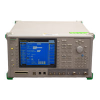
Anritsu MT8820A Operation Manual (390 pages)
Radio Communication Analyzer
Brand:
Anritsu
| Category:
Measuring Instruments
| Size: 3 MB
Table of Contents
Safety Symbols
2
Symbols Used in Manual
2
For Safety
3
Equipment Certificate
7
Anritsu Warranty
7
Notes on Export Management
8
CE Conformity Marking
10
About this Manual
13
Checking Accessories
14
Notations in this Manual
17
Table of Contents
18
Product Overview
21
Features
22
Product Configuration
23
Standard Configuration
23
Warranty & Service
27
Specifications
28
Setup
33
Part Names and Functions
34
Exterior
34
Front Panel
35
Rear Panel
45
Installation
49
Transportation
49
Piggyback Installation
52
Installation on Rack
53
Power Connection
54
Power Requirements
54
Connecting the Power Cord
54
Connecting to Phone
56
Connecting GPIB Cable
57
RS-232C Port
58
Base-T Port
58
Reference Signal Input/Output Connector
59
Event Trigger Connector
59
Serial Port
60
Call Processing I/O Port
61
Checking Power to be Input to Connector
67
Memory Card
68
Precautions for Use
68
Inserting and Removing Memory Card
69
Formatting Memory Card
69
Getting Started
71
Power-On
72
Initialization
74
Selecting Screen
75
Viewing Screen
76
Calibration
78
Setting Parameter
79
Measurement
81
Reading Measurement Results
82
Power-Off
84
Basic Operation
85
Display Area
87
Measurement-Indicator/Error-Status Area
89
User Menu Area
90
Window Area
90
Entry Area
90
Function Menu Area
90
Transmission-Power Monitor-Value Area
90
Operating Cursor
91
Cursor Type
91
Moving Cursor
92
Operating Screen
93
Screen Type
93
Selecting Screen
94
Scrolling Screen
97
Change Screen Color Pattern
98
Operating Window
99
Window Type
99
Window Status
99
Activating Window
100
Changing Window Size
100
Scrolling Window
101
Operating User Menu
102
Executing User Menu
102
Operating Function Menu
103
Viewing Function Menu
103
Switching Menu Page
104
Displaying Menu List of All
106
Types of Function Menus
107
Execution Menu
108
Numeric Value Entry Menu
108
Character String Entry Menu
110
Item Display Menu
110
Item Selection Menu
111
Tag Selection Menu
111
Toggle Menu
112
Screen Selection Menu
112
Setting Parameters
113
Settable Parameters
113
Parameter Type
113
Parameter Setting Procedures
114
Setting List Selection Type Parameter
114
Setting Numeric Value Type Parameter
115
Setting Numeric Value Group Type Parameter
117
Setting Character String Parameter
118
Setting Channel, Frequency or Level
119
Tag Operation
121
Tag Status
121
Activating Tag
122
Jump to Tag
123
Operating Template
124
Opening Template
124
Closing Template
124
Operating View Window
125
Opening View Window
125
Closing View Window
125
Using Common Functions
127
Initialization
128
Calibration
129
Calibrating Communication System Band
129
Calibrating All Input/Output Bands
130
Starting Measurement
131
Measurement Mode
131
Starting Measurement in Single Mode
131
Starting Measurement in Continuous Mode
131
Starting Measurement in Synchronous Single Mode
132
Stopping Measurement
132
Connecting Call
133
Ending Call
134
Hard Copy
135
Media and Format of Saving Destination
135
Taking Hard Copy
135
Functions Can be Set Only for Remote Control
136
Setting LCD Power Source
136
Setting Image Operation
136
Setting Delimiter
136
Setting Terminator
136
Setting Processing at Error Occurrence
137
Other Functions
138
Outputting Non-Modulation CW Signals
138
Common Screen Functions
139
Setting Systems and Interfaces
141
Opening System Configuration Screen
141
Viewing System Configuration Screen
142
Setting Reference Frequency
148
Displaying Date/Time or Character String
149
Setting Character String to be Displayed
150
Setting Date Display Format
151
Setting Date
152
Setting Time
153
Setting Beep Sound
154
Setting Signal Output Connector
154
Setting GPIB Address
156
Setting Baud Rate for RS-232C (Serial)
156
Setting Parity for RS-232C (Serial)
157
Setting Date Bit for RS-232C (Serial)
157
Setting IP Address and Subnet Mask for 10Base-T
158
Setting Stop Bit for RS-232C (Serial)
158
Setting 10Base-T Default Gateway
160
Selecting Measurement Application to be Activated
161
Opening Standard Load Screen
161
Viewing Standard Load Screen
161
Phone Switching Operation
162
Loading Measurement Application
163
Unloading Measurement Application
163
Displaying System Information
164
Opening System Information Screen
164
Viewing System Information Screen
165
Checking Maintenance Information
170
Checking Software Version
170
Checking Software Option
170
Checking Hardware Revision
170
Outputting System Information Parameters
171
Setting Common Cable Loss
172
Opening Common Cable Loss
172
Viewing Common Cable Loss
173
Setting Common Cable Loss List
177
Deleting Common Cable Loss List
178
Editing Common Cable Loss List
178
Saving Common Cable Loss List
179
Recalling Common Cable Loss List
180
Opening Common Cable Loss Graph
180
Viewing Common Cable Loss Graph Window
181
Setting the Start Frequency of Common Cable Loss Graph
184
Setting the Stop Frequency of Common Cable Loss Graph
184
Common Cable Loss Graph
184
Saving Parameters
186
Parameter Saving Function
186
Saving Destination of Parameter File
186
Parameter Saving Method
187
Quick Saving
187
Quick Saving with Specified Number
188
Opening Parameter Save Screen
188
Viewing Parameter Save Screen
189
Saving File with Specified File Name
192
Overwrite Saving
193
Updating Media Information
193
Recalling Parameters
194
Parameter Recalling Function
194
Parameter Recalling Destination
194
Parameter Recalling Method
194
Quick Recalling
195
Opening Parameter Recall Screen
195
Viewing Parameter Recall Screen
196
Recalling with File Name Specified
199
Reloading Media Information
199
Remote Control Using PC
201
Remote Control
203
What Remote Control Can Do
203
Operation in Remote Control Mode
203
Operation in Manual Operation Mode
203
Interface
204
Difference between Manual Operation and Remote Control
204
Switching between Control Modes
205
GPIB Interface
206
Device
206
Communications between Devices
206
Talker and Listener
206
Controller
206
Program Message and Response Message
207
Programming Command and Query
207
Overlap Command
207
Command Notations in this Manual
208
Communication Flow between Devices
208
Setup of GPIB
209
Network Configuration
210
Conditions for Network Configuration
211
Serial Interface
212
Serial (RS-232C) Standards
212
Program Message and Response Message
212
Programming Command and Query
213
Overlap Commands
213
Command Notations in this Manual
213
Communication Flow between Devices
214
Command Syntax
215
Elements of Command Syntax
215
Setting Parameters with Unit Specified
217
Response Unit
218
Command Programming Guide
219
Status Report
220
Standard Status Model
221
Standard Event Status Register
222
Standard Event Status Enable Register
224
Status Byte Register
225
Service Request Enable Register
227
END Event Status Register
228
END Event Status Enable Register
231
ERR Event Status Register
232
ERR Event Status Enable Register
234
Establishing Synchronization
236
Difference of Synchronization Depending on Measurement Start Command
236
Establishing Synchronization with *OPC? Query
236
Establishing Synchronization Corresponding to Status Register Status
236
Remote Control Commands
237
Command List by Function
240
IEEE488.2 Common Commands
241
Extended Event Status Commands
242
Initialization Commands
242
Measurement Software Selection Commands
243
Measurement Commands
245
Calibration Execution Commands
245
Maintenance
246
System Screen Tab Selecting Commands
246
System Setting Commands
247
System Information Query Commands
249
Common Cable Loss Setting Commands
252
Parameter Save Commands
253
Parameter Read Commands
253
Special Commands
254
Command Specifications in Alphabetical Order
255
Cls
256
Ese
257
Esr
258
Idn
259
Opc
260
Rst
261
Sre
262
Stb
263
Trg
264
Tst
265
Wai
266
Alarm
267
Bandcal
268
Baud
269
Bep
270
Bzr
271
Conts
272
Date
273
Datemode
274
Dellosstbl
275
Delm
276
Displ
277
Dtab
278
Ese2
279
Ese3
281
Esr2
283
Esr3
285
Fullcal
287
Fullcal_Tm
288
Gtl
289
Ini
290
Losstblsample
292
Losstblval
293
Lossview_Stafreq
294
Lossview_Stpfreq
295
Lossview_Vscale
296
Mccf
297
Mcfv
298
Mchv
299
MCIV
302
Mcmsv
303
Mcopt
304
Mcov
305
Mcsopt
306
Mcsv
307
Measstop
308
Mod
309
Pre
310
Preset
311
Prmrecall
312
Prmrecallname
313
Prmsave
314
Prmsavename
315
Prty
316
Psetdefgtwy
317
Psetipaddr
318
Psetsnm
319
Ref
320
Remdisp
321
Rfout
322
Rlcd
323
Rlflist
324
Rllosstbl
325
Scract
328
Screen
329
Scrsel
330
Serial
331
Sngls
332
Stdload
333
Stdsel
334
Stdunload
335
Stpb
336
Svcd
337
Svdeffile
338
Svflist
339
Svlosstbl
340
Swp
341
Sysinfosave
342
Tagsel
343
Time
344
Title
345
Tmcnt
346
Trm
347
Ttl
349
Winsize
350
Performance Test
352
Purpose and Implementation Timing
352
Performance Test Items
353
Frequency Stability for Reference Oscillator
354
VSWR Value for Main Input/Output Connector
357
VSWR Value for aux Output Connector
359
Output Frequency of the RF Signal Generator
361
Output Level Accuracy of RF Signal Generator
363
Non-Harmonic Spurious
366
Harmonics
368
Example of Performance Test Result Record Sheet
369
Calibration
376
Purpose and Implementation Timing
376
Required Measurement Device
376
Calibration of Reference Oscillator Frequency
377
Cleaning
379
Cleaning the Cabinet
379
Cleaning Others
379
Storage and Transportation
380
Packing
380
Precautions on Storage and Transportation
380
Troubleshooting
382
Index
390
Advertisement
Anritsu MT8820A Operation Manual (296 pages)
Radio Communication Analyzer
Brand:
Anritsu
| Category:
Measuring Instruments
| Size: 2 MB
Table of Contents
Table of Contents
15
About this Manual
11
Table of Contents
15
Section 1 Product Overview
19
Features
21
Product Overview
21
Options
22
Product Configuration
22
Standard Configuration
22
Application Parts
23
Measurement Software and Options
23
Warranty Service
24
Specifications
25
Section 2 Setup
27
Setup
27
Exterior
29
Part Names and Functions
29
Front Panel
30
Rear Panel
40
Installation
44
Transportation
44
Installation
45
Installation on a Rack
47
Piggyback Installation
47
Checking the Power Voltage
48
Connecting a Power Cable
48
Connection
48
Protective Grounding
49
Connecting to a Phone
50
Connecting a GPIB Cable
51
Base-T Port
52
RS-232C Port
52
Event Trigger Connector
53
Reference Signal Input/Output Connector
53
The Call Processing Port
54
Checking Power to be Input to Connector
59
Formatting a Memory Card
60
Inserting and Removing the Memory Card
60
Memory Card
60
Precautions for Use
60
Section 3 Getting Started
61
Getting Started
61
Power-On
63
Initialization
64
Selecting a Screen
65
Viewing a Screen
66
Calibration
68
Setting a Parameter
69
Measurement
71
Reading Measurement Results
72
Power-Off
74
Section 4 Basic Operation
75
Basic Operation
75
Display Area
77
Names and Positions in Display Area
77
Status Area
78
Measurement-Indicator/Error-Status Area
79
Entry Area
80
Function Menu Area
80
Transmission-Power Monitor-Value Area
80
User Menu Area
80
Window Area
80
Cursor Type
81
Operating a Cursor
81
Moving a Cursor
82
Operating a Screen
83
Screen Type
83
Selecting a Screen
83
Scrolling a Screen
86
Change the Screen Color Pattern
87
Operating a Window
88
Window Type
88
Activating a Window
89
Changing the Window Size
89
Scrolling a Window
90
Executing a User Menu
91
Operating a User Menu
91
Operating a Function Menu
92
Viewing a Function Menu
92
Switching a Menu Page
93
Displaying the Menu List of All
95
Types of Function Menus
96
Execution Menu
97
Numeric Value Entry Menu
97
Character String Entry Menu
98
Item Display Menu
98
Item Selection Menu
99
Tag Selection Menu
100
Toggle Menu
100
Parameter Type
101
Settable Parameters
101
Setting Parameters
101
Parameter Setting Procedures
102
Setting a List Selection Type Parameter
102
Setting a Numeric Value Type Parameter
103
Setting a Numeric Value Group Type Parameter
105
Setting a Character String Parameter
106
Setting Channel, Frequency or Level
107
Tag Operation
109
Activating a Tag
110
Jump to a Tag
111
Closing a Template
112
Operating a Template
112
Closing a View Window
113
Opening a View Window
113
Operating a View Window
113
Section 5 Using Common Functions
115
Using Common Functions
115
Initialization
117
Calibrating the Communication System Band
118
Calibration
118
Calibrating All Input/Output Bands
119
Starting a Measurement
120
Starting a Measurement in the Continuous Mode
120
Starting a Measurement in the Single Mode
120
Starting a Measurement in the Synchronous Single Mode
121
Stopping a Measurement
121
Connecting a Call
122
Ending a Call
123
Hard Copy
124
Media and Format of the Saving Destination
124
Taking a Hard Copy
124
Functions Can be Set Only for the Remote Control
125
Outputting Non-Modulation CW Signals
125
Setting a GPIB Terminator
125
Setting an Image Operation
125
Setting the LCD Power Source
125
Setting a Processing at an Error Occurrence
126
Section 6 Common Screen Functions
127
Common Screen Functions
127
Opening the System Configuration Screen
129
Setting Systems and Interfaces
129
Viewing the System Configuration Screen
130
Setting the Reference Frequency
134
Displaying the Date/Time or a Character String
135
Setting the Character String to be Displayed
136
Setting the Date Display Format
136
Setting the Date
137
Setting the Time
138
Setting the Beep Sound
139
Setting the Signal Output Connector
139
Setting IP Address and Subnet Mask for
140
Setting the GPIB Address
140
Setting 10Base-T Default Gateway
142
Displaying System Information
143
Opening the System Information Screen
143
Viewing the System Information Screen
143
Parameter Saving Function
145
Parameter Saving Method
145
Saving Destination of a Parameter File
145
Saving Parameters
145
Quick Saving
146
Quick Saving with a Specified Number
146
Opening the Parameter Save Screen
147
Viewing the Parameter Save Screen
147
Saving a File with Specified File Name
151
Overwrite Saving
152
Updating Media Information
152
Parameter Recalling Destination
153
Parameter Recalling Function
153
Parameter Recalling Method
153
Recalling Parameters
153
Opening the Parameter Recall Screen
154
Quick Recalling
154
Viewing the Parameter Recall Screen
155
Recalling with a File Name Specified
158
Reloading Media Information
158
Section 7 Remote Control Using PC
159
Remote Control Using PC
159
Interface
161
Operation in Manual Operation Mode
161
Operation in Remote Control Mode
161
Remote Control
161
What Remote Control Can Do
161
Difference between Manual Operation and Remote Control
162
Switching between Control Modes
162
Communications between Devices
163
Controller
163
Device
163
GPIB Interface
163
Talker and Listener
163
Command Notations in this Manual
164
Overlap Command
164
Program Message and Response Message
164
Programming Command and Query
164
Communication Flow between Devices
165
Network Configuration
166
Setup
166
Conditions for Network Configuration
167
Command Syntax
168
Elements of Command Syntax
168
Setting Parameters with Unit Specified
169
Response Unit
171
Command Programming Guide
172
Status Report
173
Standard Status Model
174
Standard Event Status Register
175
Standard Event Status Enable Register
177
Status Byte Register
178
Service Request Enable Register
180
END Event Status Register
181
END Event Status Enable Register
183
ERR Event Status Register
184
ERR Event Status Enable Register
186
Difference of Synchronization Depending on Measurement Start Command
187
Establishing Synchronization
187
Section 8 Remote Control Commands
189
Command List by Function
191
IEEE488.2 Common Commands
192
Extended Event Status Commands
193
Initialization Commands
193
Measurement Software Selection Commands
193
Measurement Commands
194
Screen Selection Commands
194
Parameter Read Commands
197
Parameter Save Commands
197
Special Commands
198
Command Specifications in Alphabetical Order
199
Cls
200
Ese
201
Esr
202
Idn
203
Opc
204
Rst
205
Sre
206
Stb
207
Trg
208
Tst
209
Wai
210
Alarm
211
Bep
212
Bzr
213
Conts
214
Date
215
Datemode
216
Displ
217
Ese2
218
Ese3
220
Esr2
221
Esr3
223
Fullcal_Tm
224
Gts
225
Ini
226
Mcfv
228
Measstop
229
Pre
230
Preset
231
Prmrecall
232
Prmrecallname
233
Prmsave
234
Prmsavename
235
Psetdefgtwy
236
Psetipaddr
237
Psetsnm
238
Ref
239
Remdisp
240
Rfout
241
Rlcd
242
Rlflist
243
Screen
246
Scrsel
247
Serial
248
Sngls
249
Stdsel
250
Svcd
251
Svdeffile
252
Svflist
253
Swp
254
Tagsel
255
Time
256
Title
257
Tmcnt
258
Trm
259
Ttl
261
Section 9 Maintenance
263
Performance Test
265
Performance Test Items
265
Purpose and Implementation Timing
265
Required Measurement Equipment
265
Frequency Stability for Reference Oscillator
267
VSWR Value for Main Input/Output Connector
269
VSWR Value for AUX Output Connector
271
Output Frequency of the RF Signal Generator
272
Output Level Accuracy of RF Signal Generator
274
Non-Harmonic Spurious
277
Harmonics
278
Example of Performance Test Result Record Sheet
280
Calibration
287
Calibration of Reference Oscillator Frequency
287
Purpose and Implementation Timing
287
Required Measurement Device
287
Cleaning
290
Cleaning Others
290
Cleaning the Cabinet
290
Packing
291
Precautions on Storage and Transportation
291
Storage and Transportation
291
Troubleshooting
293
Anritsu MT8820A Service Manual (108 pages)
Radio Communication Analyzer
Brand:
Anritsu
| Category:
Measuring Instruments
| Size: 3 MB
Table of Contents
Table of Contents
6
For Safety
3
About this Manual
5
Table of Contents
6
General
7
Circuit Description
7
Outline
10
Circuit Description
10
Signal Lines Description
18
Circuit Description of each Unit
23
A01 Main CPU Unit
23
A41, A42 WCDMA COM Unit
26
A51, A52 WCDMA BB Unit
29
A61, A62 MEAS DSP Unit
31
A02 DAC/ADC Unit
35
A71, A72 RF Unit
38
A7104, A7204 if
41
A7103, A7203 Rf
41
A7102, A7202 Output AMP
41
A7101, A7201 Input LPF
41
A81, A82 Local Unit
42
A04 Reference Unit
47
A05 Mother Board
51
A07 Panel Control Unit
52
Power Supply Unit
55
A21, A22 TDMA COM Unit
56
A03 AUDIO Unit
61
Table of Contents
65
Outline
66
Service Kits
66
Troubleshooting
66
Instruments Required for Troubleshooting
69
Circuit Reference
70
Outline of Troubleshooting Procedure
71
Overall Troubleshooting
71
Power and Control Troubleshooting
72
Output Frequency Troubleshooting
74
Input Frequency Troubleshooting
77
Output Level Troubleshooting
78
Txpower Troubleshooting
80
Section 4 4 4 4 Adjustment Andsectionsectionadjustment and C C C C Ompensationadjustment Andompensation
83
Adjustment and Compensation
84
Outline
84
Instruments Required for Adjustment and Compensation
85
Change Parts on A01 MAIN CPU UNIT
86
Carrier Leak Adjustment
87
Output Level and Input Frequency Character Compensation
90
FM Deviation Adjustment
91
Table of Contents
93
Mechanical Configuration
94
Outline
94
Cabinet and Shield Case Assembly
95
Main Unit Removal
97
Removing A01 MAIN CPU (1)
97
Removing A02 DAC/ADC (7)
97
Removing A41, A42 WCDMA COM
97
Removing A51, A52 WCDMA BB (5, 9)
97
Removing A61, A62 MEAS DSP (6, 8)
97
Removing A04 REFERENCE (18)
98
Removing A71, A72 RF (14, 15)
98
Removing A81, A82 LOCAL (16, 17)
98
Removing A05 MOTHER BOARD (19)
99
Removing A07 PANEL CONTROL (20)
99
Removing A09 KEY PANEL (21)
99
Removing POWER DIVIDER (25)
99
Removing POWER SUPPLY UNIT (22)
99
Removing A03 AUDIO (13)
100
Removing A21 / A22 TDMA COM (2, 12)
100
Removing S-ATT (23) and (24)
100
Built-In Option Unit
101
Built-In Option Analog Unit (for Parallel Phone)
102
Parts Lists
103
Advertisement
Advertisement
Related Products
Anritsu MT8852B-040
Anritsu MT8852B-041
Anritsu MT8852B-042
Anritsu MT8852B-043
Anritsu MT8801C
Anritsu MT8820C
Anritsu MT8821C
Anritsu MT8802A
Anritsu MT8815A
Anritsu BTS Master MT8220T
Anritsu Categories
Measuring Instruments
Test Equipment
Portable Generator
Control Unit
Thermometer
More Anritsu Manuals
Login
Sign In
OR
Sign in with Facebook
Sign in with Google
Upload manual
Upload from disk
Upload from URL