Table of Contents
Advertisement
Quick Links
Download this manual
See also:
Operating Manual
Advertisement
Chapters
Table of Contents

Related Manuals for Anritsu MT8801C


Summary of Contents for Anritsu MT8801C
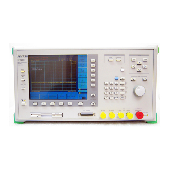
- Page 1 MT8801C Radio Communication Analyzer Option 10/11: Audio Test Operation Manual (Panel Operation)
-
Page 2: Table Of Contents
Table of Contents For Safety ............About This Manual ........Section 1 General ......... 1.1 General ................1.2 Manual Composition ............1.3 Equipment Configuration ..........1.4 Optional Accessories and Peripherals ......1.5 Specifications ..............Section 2 Preparations Before Use .... 2.1 Installation Site and Environmental Conditions .... - Page 3 4.6 Reception Audio Measurement –– RX Audio screen ..4-21 4.7 Audio Echo Measurement –– Audio Echo screen ..4-23 4.8 Saving and recalling parameter data –– Save Parameter screen, Recall Parameter screen ..4-25 4.9 Operating the file –– File Operation screen ....4-30 4.10 Screen hard copy ––...
-
Page 5: Section 1 General
Section 1 General General ..............Manual Composition ..........Equipment Configuration ........... 1.3.1 Standard configuration ........1.3.2 Options ............Optional Accessories and Peripherals ...... Specifications ............ -
Page 6: General
The MT8801C equipped with Options 10/11 GSM Audio Test, can be used as an integrated measuring instrument for measuring the audio input/output performance of a radio conforming to the Full Rate Speech Transcoding recommended by GSM. -
Page 7: Manual Composition
1.2 Manual Composition Manual Composition This manual is made up of the following Sections. Section 1 General Describes the introduction, composition, function specifications and performance of this instrument. Section 2 Preparations before Use Explains various work to be performed before using this instrument. Section 3 Panel Layout and Overview of Operation Explains the basic items for operating this equipment. -
Page 8: Equipment Configuration
This paragraph describes the configuration of the MT8801C Radio Communication Analyzer (with options 10/11) with standard accessories. 1.3.1 Standard configuration The table below shows the configuration of the Options 10/11 of the MT8801C with the standard accessories. Table 1-1 Standard Composition Item Order No. -
Page 9: Optional Accessories And Peripherals
1.4 Optional Accessories and Peripherals Optional Accessories and Peripherals The following table shows the optional accessories and peripherals for the MT8801C which are all sold separately. Table 1-3 Optional Accessories and Peripherals <Optional accessories> Model*/Order No. Name* Remarks J0127C Coaxial cord BNC-P·RG-58A/U·BNC-P, 0.5 m... -
Page 10: Specifications
Section 1 General Specifications The MT8801C specifications are listed in Tables 1-4 and 1-5 below. Table 1-4 MT8801C Specifications Frequency range 300 kHz to 3 GHz +40 dBm (10 W) (MAIN connector) Maximum input level +20 dBm (100 mW) (auxiliary input connector) N-type connector Impedance 50 Ω,... - Page 11 Measuring the frequency and level of the audio signal that conforms to Full Rate Speech Transcoding recommended by GSM Electrical characteristics: The following specifications are guaranteed after the MT8801C internal level is opti- mized and level calibration (performed automatically when a key is pressed) is per- formed.
- Page 12 Section 1 General 1-8.
-
Page 13: Section 2 Preparations Before Use
Section 2 Preparations Before Use Installation Site and Environmental Conditions ..Safety Measures ............2.2.1 Safety measures for power supply ....2.2.2 Maximum power to connector ....... Preparations before Power-on ........2.3.1 Protective grounding ........2.3.2 Replacing fuse ..........Installation ..............2-10 2.4.1 Rack mounting .......... -
Page 14: Installation Site And Environmental Conditions
MT8801C has been allowed to dry out sufficiently. Fan clearance: To suppress any internal temperature increase, the MT8801C has a fan on the rear panel as shown in the diagram below. Leave a gap of at least 10 cm between the rear panel and the wall, nearby equipment or obstructions so that fan ventilation is not blocked. -
Page 15: Safety Measures
Safety measures for power supply WARNING Before power-on: • Protective grounding The MT8801C must be connected to ground. If the power is turned on without taking this countermeasure, there is a risk of receiving an accidental electric shock. • Power supply voltage In addition, it is essential to check the power supply volt- age. -
Page 16: Maximum Power To Connector
Section 2 Preparations Before Use 2.2.2 Maximum power to connector The allowable maximum power to the MT8801C connectors are as follows. Connector Allowable maximum power Main Input/Output 10 W (40 dBm) AUX Input 100 mW (20 dBm) AUX Output Exclusive output connector, 0.5 mW (–3 dBm) -
Page 17: Preparations Before Power-On
2.3 Preparations before Power-on Preparations before Power-on The MT8801C operates normally when connected to 100 to 120 Vac, 47.5 to 63 Hz, or 200 to 240 Vac, 47.5 to 63 Hz AC power supply via the power inlet. To prevent the following problems, take the necessary procedures described on the following pages before power is supplied. -
Page 18: Protective Grounding
The power supply polarity of the 3-pole (grounded, 2-pole type) matches that of the 3-core power cord plug. Therefore, the MT8801C is connected to ground potential when the power cord is connected to the plug. As a result, it is not necessary to connect the FG terminal to ground. - Page 19 (FG) terminal on the rear panel must be connected to ground potential before power is supplied to the MT8801C. Fuse holder Label indicating protective ground terminal...
-
Page 20: Replacing Fuse
Section 2 Preparations Before Use 2.3.2 Replacing fuse The MT8801C with standard accessories has two spare fuses (T6.3A250V). Use these fuses to replace the blown fuses. If the fuses must be replaced, locate and rem- edy the cause before replacing the blown fuses. - Page 21 Remove the fuse from the fuse cap and replace it with a spare fuse. Return the fuse cap with the fuse to the fuse holder, then fasten it by turning it clockwise with the screwdriver. * Contact the Anritsu service department for fuses by specifying the model name, order number, name, and quantity.
-
Page 22: Installation
The installation method is included in the rack mount kit diagram. 2.4.2 Stacking When stacking several MT8801Cs or stacking the MT8801C with equipment of the same width as the MT8801C, the B0332 Coupling Plate (sold separately, Table 1-3) are required. 2-10... -
Page 23: Precautions For Handling Storage Media
2.5 Precautions for Handling Storage Media Precautions for Handling Storage Media 2.5.1 Floppy disk The following explains how to handle the floppy disk media of this instrument. Front Rear Fig. 2-1 3.5-inch Floppy Disk (1) Precautions The plastic case of the 3.5-inch floppy disk has a shutter to protect the disk inside. - Page 24 Section 2 Preparations Before Use (2) Write-protection tab A write-protection tab is provided on the 3.5-inch floppy disk. Sliding this tab downward in the arrow direction beforehand prevents accidental writing and deletion. (A write operation is disabled in this state.) Write enable Write disable Fig.
-
Page 25: Section 3 Panel Layout And Overview Of Operation
Section 3 Panel Layout and Overview of Operation Panel Layout ............. 3.1.1 Front panel layout ......... 3.1.2 Rear panel layout .......... 3.1.3 Panel layout ..........Overview of Operation ..........3.2.1 Overview of functions ........3.2.2 Overview of Operation ........ -
Page 26: Panel Layout
Section 3 Panel Layout and Overview of Operation Panel Layout This paragraph describes the keys, switches, lamps, and connectors on the front and rear panels of the MT8801C Radio Communication Analyzer. 3.1.1 Front panel layout This paragraph describes the keys, switches, lamp, connectors, and the rotary knob on the front panel. - Page 27 3.1 Panel Layout Display Function outline Key group for entering data. Shift Switches the function of keys with a shift function. When the shift key is pressed, the key’s lamp goes on. Subsequent operation must be started with this lamp on. Back space key used to correct input data.
- Page 28 Section 3 Panel Layout and Overview of Operation Display Function outline 10 Main Input/Output Input/output connector for RF signal. (N type connector) 11 AUX Auxiliary input/output connectors for RF signal. (TNC connector) Input Auxiliary input connector for RF signal. This is used when the output level of DUT is too low.
-
Page 29: Rear Panel Layout
3.1 Panel Layout 3.1.2 Rear panel layout This paragraph describes the switch and connectors on the rear panel. Display Function 19 O I Input switch for AC power supply. If this switch is turned off, the Power switch on the front panel cannot be turned on. -
Page 30: Panel Layout
The front panel and rear panel layouts are shown in Figs. 3-1 and 3-2, respectively. The numbers in the diagram correspond to those in paragraphs 3.1.1 and 3.1.2. 1 2 3 4 Measure Cursor Single Continuous MT8801C Cancel Radio Communication Analyzer 300kHz-3GHz Copy Preset... -
Page 31: Overview Of Operation
AF signal outputted from the MT8801C is encoded, and the RF signal is modulated by the audio-encoded signal in the radio under test. The sent data in the RF signal of the radio is echoed back from the MT8801C to the radio, and the level and frequency of the demodulated/audio-decoded audio signal of the radio are measured by the MT8801C. - Page 32 Section 3 Panel Layout and Overview of Operation (4) Outline of screen configuration The screen configuration is shown below. A tree-shaped Hierarchical configuration of items below the main menu is indicated. (Details of operation are explained in Section 4. The screens, setup items and function key flowchart for each screen are summarized in Appendix A, “Screen and Function Key Transition Diagrams.”) [Overview of screens] •...
-
Page 33: 3.2 Overview Of Operation
(Screen for changing TX & RX Tester mode measurement system) • Instrument Setup mode Instrument Setup screen (Screen for setting up RS232C/GPIB, etc. for MT8801C main frame) Note: Change Color mode (Selection for screen display color) is setup using the... - Page 34 Section 3 Panel Layout and Overview of Operation 3-10.
-
Page 35: Section 4 Operation
Section 4 Operation Describes the operation of the Option 10/11 Audio Test of the MT8801C Radio Com- munication Analyzer. Turning on and off the Power ........Screen Descriptions ..........Preparation ..............4-15 Setting Common Measurement Parameter –– Setup Common Parameter screen ....... 4-17 Transmission Audio Measurement ––... -
Page 36: Turning On And Off The Power
Section 4 Operation Turning on and off the Power The MT8801C has two power switches: The Stby/On switch on the front panel and (main power) switch on the rear panel. MT8801C front panel Measure Cursor Stby Single Continuous MT8801C Cancel... - Page 37 Frequency: 47 to 63 Hz For normal MT8801C operation, leave the power switch on the rear panel set to on when the AC power inlet is connected to the power outlet, and only use the Stby/On switch on the front panel to turn the power on and off.
- Page 38 The On lamp on the front panel power switch Stby Stby Stby/On switch on lights and the Stby lamp goes off. the front panel for a few seconds to set it Power is supplied to all circuits in the MT8801C, then the MT8801C becomes operable.
- Page 39 Notes: The below figure shows the reference signal input/output connectors on the MT8801C rear panel. The internal 10 MHz reference signal is output from the 10 MHz OUTPUT connector at TTL level. When the internal reference signal is not used, input an external reference signal satisfying the following condi- tions to the 10 MHz/13 MHz Reference Input connector: i) Frequency: 10 MHz ±1 ppm, signal level: 2 to 5 Vp-p...
- Page 40 Section 4 Operation 4.1.2 Turning off the Power Turn off the power as described below. (1) Normal power-off procedures Step Operation Result check Press the Stby/On • The On lamp of the Power switch on the front panel Stby On Stby On switch on the front goes off, and the Stby lamp lights.
-
Page 41: Screen Descriptions
Main Input/Output AUX Input/Output (5) Calibrated display If the MT8801C is already calibrated, “C” is displayed on the second line from the top center. This is appeared after executing calibration in the RF Level/Power on the TX Measure screen. - Page 42 Section 4 Operation (6) User calibration factor setting display If a user calibration coefficient is being set, “U” is displayed on the third line from the top center. This is appeared when the user Cal. factor is set at the Setup TX Measure Pa- rameter Screen.
- Page 43 4.2 Screen Descriptions [F7] 1. Title/date and time 2. Screen name 3. Measurement error or [F8] measurement being performed 4. RF input switching [F9] 5. Calibrated display 6. User Cal display 7. Measurement mode [F10] 8. Storage mode [F11] [F12] [F1] [F2] [F3]...
- Page 44 Section 4 Operation 4.2.2 Function keys The symbols displayed on the top right of the function keys indicate the following functions: Indicates a lower level function key is displayed when this function key is pressed. → : Indicates the screen is changed by pressing this function key. Indicates a window is opened to set a value using the ten-keypad, Step key, or rotary knob when this function key is pressed.
- Page 45 4.2 Screen Descriptions (5) Menu on which a set item is selected [Example of the function key menu] Modulation AF Osc.1 Selected item Frequency AF Osc.1 Deviation AF Osc.1 Back Screen [Example of the main function key menu] Call Audio Echo Back Main Func Measure...
- Page 46 Section 4 Operation 4.2.3 Entering data (1) Entering numeric data by opening/closing the window Entering numeric data by moving the cursor and opening/closing the win- dow. Move the cursor to the brackets enclosing the item to be set, then press the Set key.
- Page 47 4.2 Screen Descriptions (2) Entering selection item by opening/closing the window Move the cursor to the brackets enclosing the item to be set, then press the Set key. The selected item setting window shown below is opened and the selected item can be set.
- Page 48 Section 4 Operation (4) Entering selected items using function keys with lower hierarchy When the key marked * on the top right of the menu is pressed, the menu set of the lower hierarchy shown below is displayed. Select an item from the menu set and press the corresponding function key. The menu display of the selected item is changed.
-
Page 49: Preparation
4.3 Preparation Preparation In order to use the GSM Audio Test, the MT8801C and the radio under test should be in the communication state. In the following description, it is assumed that the MT8801C and the radio under test are in the communication state. Refer to “MX880115A Operation Manual, Section 4 Operation”... - Page 50 MT8801C is encoded, and the RF signal is modulated by the audio-encoded signal in the radio under test. The sent data in the RF signal of the radio is echoed back from the MT8801C to the radio, and the level and frequency of the demodulated/audio-decoded audio signal of the radio are measured by the MT8801C.
-
Page 51: Setting Common Measurement Parameter -- Setup Common Parameter Screen
4.4 Setting Common Measurement Parameter –– Setup Common Parameter screen Setting Common Measurement Parameter –– Setup Common Parameter screen This paragraph describes newly added items and items whose setting range is changed for Options 10/11. Note: Refer to the MX880115A GSM Measurement Software operation manual for the items that are not described below. - Page 52 [Echo Back]: A function in which the MT8801C loops back the communication channel informa- tion of the radio under test in the communication state with the MT8801C. [Loop Back]: A function in which the radio under test in the communication state with the MT8801C loops back the communication channel information sent by the MT8801C.
-
Page 53: Transmission Audio Measurement -- Tx Audio Screen
Displays the channel in communication with the radio under test. RX Output Level Displays the level of the RF signal outputted from the RF Output connector of the MT8801C. Frame noise measurement function: A 217 Hz signal of frame noise can be measured by setting the AF frequency to 217 Hz. -
Page 54: Timing Of Transmission Audio Measurement
Input / Output 300kHz-3GHz 50Ω 10W Max 20dBm Max AF signal After 50 ms from measurement start, MT8801C starts outputting AF signal which Measurement start Measurement end continues for approximately 550 ms. AF signal outputted from AF Output connector of MT8801C... -
Page 55: Reception Audio Measurement -- Rx Audio Screen
Displays the channel in communication with the radio under test. RX Output Level Displays the level of the RF signal outputted by the MT8801C from the RF Output connector. Frame noise measurement function: A 217 Hz signal of frame noise can be measured by setting the AF frequency to 217 Hz. -
Page 56: Timing Of Reception Audio Measurement
AF signal Measurement start Measurement end which continues for approximately 660 ms. AF signal de-coded at radio under test AF signal inputted to AF Input connector of MT8801C After approximately from measurement start, data for 128 ms interval is used. 4-22... -
Page 57: Audio Echo Measurement -- Audio Echo Screen
AF signal outputted from the MT8801C is encoded, and the RF signal is modulated by the audio-encoded signal in the radio under test. The sent data in the RF signal of the radio is echoed back from the MT8801C to the radio, and the level and frequency of the demodulated/audio-decoded audio signal of the radio are measured by the MT8801C. -
Page 58: Timing Of Audio Echo Measurement
Measurement end which continues for approximately 1 s. AF signal outputted from AF Output connector of MT8801C MT8801C stores data for 920 ms interval before start of de-coding AF signal at radio under test Radio under test Start of Echo Back... -
Page 59: Saving And Recalling Parameter Data
4.8 Saving and recalling parameter data –– Save Parameter screen, Recall Parameter screen Saving and recalling parameter data –– Save Pa- rameter screen, Recall Parameter screen Display the Save Parameter and Recall Parameter screens according to the following steps to save or recall parameters set for the Analog Measurement. Step key operation Description... - Page 60 • Notes when displaying the Save Parameter screen and Recall Parameter screen: Before pressing the [Save]F5 or [Recall]F4 function key, insert a floppy disk(FD) in the FD driver of the MT8801C. Then press the key. The MT8801C automatically starts the FD-driver operation.
- Page 61 4.8 Saving and recalling parameter data –– Save Parameter screen, Recall Parameter screen • Function keys on the Recall Parameter screen Main function key: None Recall function keys: [Display Dir.]F8: Accesses the floppy disk and displays the directory of the parameter data file. The lower-order Recall menu appears.
- Page 62 Description Insert a saving floppy disk (FD) into the FD driver on the bottom left of the MT8801C. [Main Func on off]F6 Sets Main Func to on. The Main Menu 1st page is displayed on the screen bottom.
- Page 63 Confirms the file to be recalled. 8. RECALL? Yes No Opens RECALL confirmation window. Select YES. The MT8801C reads the specified file. Then, returns to the previous screen, automatically. • Changing the recall-file display format (WIDE/NARROW) This paragraph describes how to change the recall-file display format (WIDE/NARROW).
-
Page 64: Operating The File -- File Operation Screen
Section 4 Operation Operating the file –– File Operation screen To access the floppy disk and display the parameter file directory, delete or write- protect the parameter file, and initialize the floppy disk; display the File Operation screen according to the following steps. Note: This function can only be executed through panel operation. - Page 65 4.9 Operating the file –– File Operation screen • Functions keys on the File Operation screen Main function key: None Function keys: 2 pages. Use the Next Menu [ ] key to scroll to the next page. ** 1st page ** [Previous Page]F7: Displays the previous page of the directory.
- Page 66 Description Insert a floppy disk (FD) into the FD driver at the bottom left of the MT8801C. [Main Func on off]F6 Turn the Main Func on to display the first page of the Main Menu at the bottom of the screen.
- Page 67 Step key operation Description Insert a floppy disk (FD) into the FD driver at the lower left of the MT8801C. The acceptable FD is the 2HD (1.44 M-bytes) or 2DD (720 k-bytes) type. Set File Operation mode, as described previously.
-
Page 68: Screen Hard Copy -- Copy
Section 4 Operation 4.10 Screen hard copy –– Copy The copy function transfers a screen display to the printer or floppy disk. Specify a transfer destination and mode on the Instrument Setup screen. Press the Copy key on the front panel to activate the Copy function. While the Copy function is operating, operations (including remote control) such as measurement or internal setting are disabled. -
Page 69: Settings Relating To Remote Control And Panel Key Control
When the panel is locked, the green lamp on the PANEL LOCK key lights. 3. Remote control status If the MT8801C is controlled remotely, the REMOTE lamp on the left of the front panel lights. While the REMOTE lamp is on, key entry and rotary encoder entry from the front panel are disabled. - Page 70 Section 4 Operation 4-36.
-
Page 71: Section 5 Performance Tests
Section 5 Performance Tests This section lists the equipment used in performing the MT8801C performance tests, and explains the setup and the performance test items of Options 10/11: Audio Test. Requirement for Performance Tests ......Instruments Required for Performance Test ..... -
Page 72: Requirement For Performance Tests
10/11: Audio Test of the MT8801C. Use the performance test procedures during acceptance inspection, periodic inspec- tion, and after repair of of Options 10/11: Audio Test of the MT8801C. Do the impor- tant parts of preventive maintenance periodically. This section explains the following test procedures: •... -
Page 73: Performance Tests
30 minutes and option 01 analog measure- ment of the MT8801C is completely stabilized. Keep AC supply voltage fluctuations, noise, vibration, dust, humidity and any other factor which could affect results to a minimum. - Page 74 (If AF OSC.2 is ON, set it to OFF.) Read the value indicated on the AF distortion rate meter. Change the AF frequency of MT8801C AF OSC.1 in accordance with the table below, and repeat the measurement. Waveform distortion of AF oscillator AF Frequency (kHz) 0.02...
-
Page 75: Audio Analyzer
Set the MT8801C to RX Measure (Analog) mode. Specify the AF oscillator level. Specify the AF oscillator frequency and read the AF level value indicated on the MT8801C. Change the frequency of the AF oscillator in accordance with the table below, and repeat the measurement. -
Page 76: Example Of Performance Test Result Entry Sheet
Example of performance test result entry sheet This paragraph gives an example of sheets used to summarize the results of a perfor- mance test on Options 10/11: Audio Test of the MT8801C. Use a copy of this sheet for the performance test. -
Page 77: Section 6 Calibration
Section 6 Calibration This section describes the measuring instruments required to calibrate the MT8801C, and the setup and calibration method for these instruments. Calibration Requirements .......... Equipment Required for Calibration ......Calibration ..............6.3.1 Calibrating the reference crystal oscillator .. -
Page 78: Calibration Requirements
Calibration should be performed periodically even if the MT8801C is operating nor- mally. We recommend that the MT8801C be calibrated once or twice a year. Contact the Service Department of Anritsu Corporation if the MT8801C fails to meet the specifications during calibration. Equipment Required for Calibration The table below shows the equipment required to calibrate each item. -
Page 79: Calibration
6.3 Calibration Calibration Do not start the performance tests until the MT8801C and measuring instruments have warmed up for at least 24 hours and they have stabilized completely. To obtain the best measurement accuracy, do the calibration at room temperature. Keep AC power voltage fluctuations, noise, vibration, dust, humidity, and any other facxtors which can affect results to a minimum. - Page 80 Set the Power switch on the MT8801C front panel to On. Apply the standard frequency signal to the external reference input of the frequency counter. Set the frequency of the signal generator of the MT8801C to 1000.000 000 MHz, the level to –28 dBm, and the modulation to off.
-
Page 81: Section 7 Storage And Transportation
Section 7 Storage and Transportation This section describes the long-term storage, repacking, and transportation of the MT8801C and the regular maintenance procedures. Cleaning the Cabinet ..........Storage Precautions ..........7.2.1 Precautions before storage ......7.2.2 Recommended storage conditions ....Repacking and Transportation ........ -
Page 82: Cleaning The Cabinet
Section 7 Storage and Transportation Cleaning the Cabinet Always turn the MT8801C power switch OFF and disconnect the power plug from the AC power inlet before cleaning the cabinet. To clean the external cabinet: • Use a soft, dry cloth. -
Page 83: Storage Precautions
7.2 Storage Precautions Storage Precautions This paragraph describes the procedures for long-term storage of the MT8801C. 7.2.1 Precautions before storage Before storage, wipe dust, finger-marks, and other contaminants off the MT8801C. Avoid storing the MT8801C where it may be exposed to: Direct sunlight or high dust levels. -
Page 84: Repacking And Transportation
Section 7 Storage and Transportation Repacking and Transportation Take the following precautions if the MT8801C must be returned to Anritsu Corpora- tion for servicing. 7.3.1 Repacking Use the original packing materials. If the MT8801C is packed in other materials, observe the following packing procedure: Wrap the MT8801C in a plastic sheet or similar material. -
Page 85: Appendix
Appendix Appendix A Screen/ Function Key Change Figure ..... A-1 Appendix B List of Initial Values ......... B-1 Appendix C Index ............... C-1 App-1... - Page 86 Appendix App-2.
-
Page 88: Appendix A Screen/ Function Key Change Figure
Appendix A Screen/ Function Key Change Figure [Change of function keys for each screen] Note: When (Back Screen) or (Return) of F12 at the bottom of the displayed function keys is selected, the screen returns to the upper screen. Audio TX Audio Tx Audio Test... -
Page 89: Appendix B List Of Initial Values
“INI” command can be initialized also by the “RST” command. • An item which is not initialized by either method is marked “NO”. The initial values of the MT8801C Options 10/11: GSM Audio Test is shown below. • TX Audio screen Item... - Page 90 Appendix B List of Initial Values B-2.
-
Page 91: Appendix C Index
Appendix C Index The numbers on the right indicate section and paragraph numbers in this operation manual. AF Input/Output connectors ..........3.1, 4.3.1 AF Measure ................3.2.1, Analog Tester ............... 3.2 Audio Echo measurement ............ 3.2.1, 4.3.3, 4.7 Audio Echo screen ..............3.2.2 (4) AUX Input/Output connectors .......... - Page 92 Appendix C Index Preparation before power-on ..........2.3 Recall ..................4.8 Receiver(RX) measurement ..........7.2.2 Recommended storage conditions ........1.1 Reference crystal oscillator ..........4.1.1 Repacking and transportation for servicing ......7.3 Replacing fuse ..............2.3.2 RS232C ................. 3.1, 4.11 RX Audio measurement ............
Need help?
Do you have a question about the MT8801C and is the answer not in the manual?
Questions and answers