Table of Contents
Advertisement
Quick Links
Advertisement
Table of Contents

Related Manuals for Hologic Faxitron CT


Summary of Contents for Hologic Faxitron CT
- Page 3 Faxitron ® Specimen Radiography System User Guide For Software Version 1.2.4 Part Number 5081-9544 Revision 004 July 2021...
- Page 4 © 2021 Hologic, Inc. Printed in the USA. This manual was originally written in English. Hologic, Faxitron, and associated logos are trademarks and/or registered trademarks of Hologic, Inc., and/or its subsidiaries in the United States and/or other countries. All other trademarks, registered trademarks, and product names are the property of their respective owners.
-
Page 5: Table Of Contents
X-Ray/Imaging Chamber Components ....................26 System Connections .............................. 27 How to Lock and Unlock a Caster ........................28 How to Move the Console ........................... 28 4: Quick Start – Basic Operation of the Faxitron CT ________________________________29 System Start-Up ..............................29 5081-9544 Revision 004... - Page 6 Faxitron CT Specimen Radiography System User Guide Table of Contents Calibration ................................30 Basic Imaging Procedure ............................. 31 4.3.1 Enter Patient Data ........................... 33 4.3.2 Acquire Images ............................34 Saving Images to PACS ............................37 Shutdown Procedure ............................37 5: Calibration __________________________________________________________________39 Image Calibration..............................
- Page 7 Faxitron CT Specimen Radiography System User Guide Table of Contents 6.13 About ..................................78 6.14 Help ..................................79 7: Quality Control ______________________________________________________________81 Required Quality Control Procedures ....................... 81 Service and Troubleshooting ..........................81 7.2.1 Service ..............................81 7.2.2 Troubleshooting ............................81 Cybersecurity ................................
-
Page 9: List Of Figures
Figure 15: Calibration Menu ............................30 Figure 16: Start Image Calibration ..........................31 Figure 17: Calibration Progress Window ........................31 Figure 18: Faxitron CT Consumable Tray ........................32 Figure 19: Specimen Orientation ........................... 32 Figure 20: Home Menu ..............................33 Figure 21: Start Procedure Menu ........................... - Page 10 Figure 71: Save Snapshot Button ........................... 62 Figure 72: Save A Snapshot Dialog..........................62 Figure 73: Save Snapshot File Types ..........................63 Figure 74: Faxitron CT (3D) Display ..........................63 Figure 75: Play Button ..............................64 Figure 76: Faxitron CT 3D View ............................ 64 Figure 77: Specimen Orientation ...........................
- Page 11 Table of Contents Figure 87: Faxitron CT Slice Views ..........................70 Figure 88: Faxitron CT MIP and Slice Views ....................... 71 Figure 89: Hounsfield Units – Fatty Tissue ........................72 Figure 90: Hounsfield Units – Denser Fibrous Tissue ....................72 Figure 91: Hounsfield Units - Calcification ........................
-
Page 13: List Of Tables
Faxitron CT Specimen Radiography System User Guide Table of Contents List of Tables Table 1: Required Procedures ............................81 Table 2: User Preventive Maintenance.......................... 85 Table 3: Service Preventive Maintenance ........................85 5081-9544 Revision 004 xiii... -
Page 15: 1: Introduction
System Capabilities The Faxitron CT system acquires and displays 2D and 3D radiographic images of surgical specimens taken from various anatomical regions. The system has the capability to transfer the images to external devices. The images acquired with this system are intended to confirm removal of a suspected lesion or pathology;... -
Page 16: User Profiles
Faxitron CT Specimen Radiography System User Guide Chapter 1: Introduction User Profiles • The Faxitron CT system does not utilize multiple User Profiles. There is a single log- in to the system software. • Service personnel have full access to all system functions. -
Page 17: Product Complaints
Chapter 1: Introduction Product Complaints Report any complaints or problems in the quality, reliability, safety, or performance of this product to Hologic. If the device has caused or added to patient injury, immediately report the incident to Hologic. 1.10 Hologic Cybersecurity Statement Hologic continuously tests the current state of computer and network security to examine possible security problems. -
Page 18: Symbols
Faxitron CT Specimen Radiography System User Guide Chapter 1: Introduction 1.11 Symbols This section describes the Symbols on this system. Symbol Description Discard electrical and electronic equipment separately from standard waste. Send decommissioned material to Hologic or contact your service representative. -
Page 19: Descriptions Of Warnings, Cautions, And Notes
Warning: Warns the reader that ionized radiation is emitted into the labeled area when the x-ray beam is energized. The Faxitron CT system has safety interlocks to prevent the labeled area from being accessed while the x-ray beam is energized. -
Page 21: 2: General Information
3. Image Display Monitor 4. Keyboard & Trackball The Faxitron CT system reconstructs excised specimens in real-time. CT is designed to help achieve better surgical outcomes and improve intraoperative specimen margin assessment by providing a full 3D reconstruction of the specimen with 0.1mm slices in the X, Y, and Z-Axes. -
Page 22: Safety Information
Always follow all the instructions in this manual. Hologic does not accept responsibility for injury or damage from incorrect system operation. Hologic can arrange for training at your site. The system has safety interlocks, but the user must understand how to safely operate the system and be aware of the health hazards of x-ray radiation. - Page 23 The protection provided by the equipment is reduced if the equipment is used in a method not specified by Hologic. WARNING! Always place the Faxitron CT system a minimum of 1.5 meters (5 feet) from the patient. WARNING! No modification of this equipment is allowed.
- Page 24 Faxitron CT Specimen Radiography System User Guide Chapter 2: General Information WARNING! Before adjusting the position of the console, make sure the power cord and any cables are safely positioned out of the way. WARNING! To prevent fire or shock hazard, do not expose the system to rain or moisture.
- Page 25 Faxitron CT Specimen Radiography System User Guide Chapter 2: General Information Warning: When moving the console, be aware of bumps, ramps, inclines, or declines. Use extra caution when moving the console on an uneven or sloped surface. Warning: Make sure there is adequate space to completely open the Imaging Cabinet door and to safely insert or remove the specimen tray.
- Page 26 Faxitron CT Specimen Radiography System User Guide Chapter 2: General Information Caution: The system is a laboratory device and not a normal computer. Do not make changes to the hardware or software that are not authorized. Install this device behind a firewall for network security.
-
Page 27: Interlock Operation
Faxitron CT Specimen Radiography System User Guide Chapter 2: General Information Interlock Operation X-ray generation stops automatically whenever the Interlock system is interrupted. The Interlock system may be interrupted due to user action, i.e., opening the chamber door, or a fault in the system, such as a failed switch or a fault in the Interlock system wiring. -
Page 28: Compliance
Faxitron CT Specimen Radiography System User Guide Chapter 2: General Information Figure 3: “CT Scan Cancelled” Error Message The system will revert to “Standby” whenever the door is opened during x-ray generation. Click the Okay button in each error message, Close and/or verify the chamber door is fully closed, The system should now be “Ready”... -
Page 29: Compliance Statements
If adjacent or stacked use is necessary, make sure that the ME Equipment or ME System operates correctly in this configuration. Caution: Changes or modifications not expressly approved by Hologic could void your authority to operate the equipment. 2.5.2... -
Page 30: Dicom Standard
• NEMA PS3 / ISO 12052, Digital Imaging and Communications in Medicine (DICOM) Standard, National Electrical Manufacturers Association, Rosslyn, VA, USA (available free at http://www.dicomstandard.org/) • See Faxitron CT DICOM Conformance Statement for more information. Page 16 5081-9544 Revision 004... -
Page 31: Interoperable Connections
Faxitron CT Specimen Radiography System User Guide Chapter 2: General Information Interoperable Connections The Faxitron CT is capable of operating as a standalone device without any input or output to other devices. Images can be captured, stored, and reviewed directly on the system. -
Page 32: Network / User Settings
Faxitron CT Specimen Radiography System User Guide Chapter 2: General Information Network / User Settings The detector on the Faxitron CT uses an ethernet (network) connection to communicate. Adding users or setting additional network security can prevent the detector from communicating to the software. -
Page 33: Label Locations
Faxitron CT Specimen Radiography System User Guide Chapter 2: General Information Label Locations Figure 4: Label Locations - Front 5081-9544 Revision 004 Page 19... -
Page 34: Figure 5: Label Locations - Back
Faxitron CT Specimen Radiography System User Guide Chapter 2: General Information NOTE: Labels C and E are from P/N 05-0260-04, Label Set, BioVision Figure 5: Label Locations - Back Page 20 5081-9544 Revision 004... -
Page 35: Figure 6: Labels A1, A2, D1, D2 & E From P/N 7120-6300 Label Set
Faxitron CT Specimen Radiography System User Guide Chapter 2: General Information Figure 6: Labels A1, A2, D1, D2 & E from P/N 7120-6300 Label Set 5081-9544 Revision 004 Page 21... -
Page 36: Figure 7: Labels C, F, K & O From P/N 7120-6300 Label Set And
Faxitron CT Specimen Radiography System User Guide Chapter 2: General Information Figure 7: Labels C, F, K & O from P/N 7120-6300 Label Set and Labels C & E from P/N 05-0260-04 Label Set Page 22 5081-9544 Revision 004... -
Page 37: Figure 8: Compliance And Identification Label, 120Vac, 2 Required
Faxitron CT Specimen Radiography System User Guide Chapter 2: General Information Figure 8: Compliance and Identification Label, 120VAC, 2 required 5081-9544 Revision 004 Page 23... -
Page 39: 3: Components, Controls, And Indicators
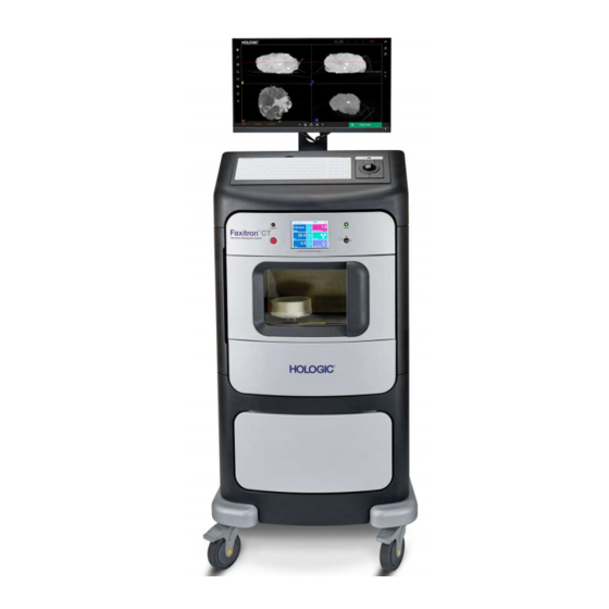
Faxitron CT Specimen Radiography System User Guide Chapter 3: Components, Controls, and Indicators Chapter 3 Components, Controls, and Indicators System Components Figure 9: System Components Figure Legend 1. Image Display Monitor 11. Trackball 2. Keyboard 12. Power ON Light 3. Touch Screen 13. -
Page 40: X-Ray/Imaging Chamber Components
Faxitron CT Specimen Radiography System User Guide Chapter 3: Components, Controls, and Indicators 3.1.1 X-Ray/Imaging Chamber Components The console houses a shielded imaging cabinet. The placement of the specimen tray determines the magnification level of the image. Figure 10: X-Ray/Imaging Chamber Figure Legend 1. -
Page 41: System Connections
Faxitron CT Specimen Radiography System User Guide Chapter 3: Components, Controls, and Indicators System Connections Power and Network Connections Figure Legend 1. System Power Switch 2. Power Cord Connection 3. Computer Reset Button 4. Ethernet Port Figure 11: Power and Network Connections Put the system in a location where you can easily access power connections and network connections. -
Page 42: How To Lock And Unlock A Caster
Faxitron CT Specimen Radiography System User Guide Chapter 3: Components, Controls, and Indicators How to Lock and Unlock a Caster • To lock a caster, step on the locking lever on the wheel until the lever locks. • To unlock a caster, press forward on the top of the locking lever until the lever snaps to the UP position. -
Page 43: 4: Quick Start - Basic Operation Of The Faxitron Ct
Quick Start – Basic Operation of the Faxitron System Start-Up Caution: The Faxitron CT has a battery back-up which allows the system to be moved without powering down. However, the system must be on mains power when capturing images, including during calibration. -
Page 44: Calibration
Note During operation the touch screen on the Faxitron CT control panel will show the status at the top of the screen. For example – Calibrating, Stand-by, and Ready. Calibration Note This section provides a summary of Image Calibration only. -
Page 45: Basic Imaging Procedure
Faxitron CT Specimen Radiography System User Guide Chapter 4: Quick Start – Basic Operation of the Faxitron CT Ensure the chamber is empty, including the foam tray, check the box to confirm the chamber is empty, then click the Start button. -
Page 46: Figure 18: Faxitron Ct Consumable Tray
Faxitron CT Specimen Radiography System User Guide Chapter 4: Quick Start – Basic Operation of the Faxitron CT Place the specimen in a Faxitron CT Specimen Tray. The specimen must fit completely within the inner ring shown below. (10 trays were provided with your system.) -
Page 47: Enter Patient Data
Faxitron CT Specimen Radiography System User Guide Chapter 4: Quick Start – Basic Operation of the Faxitron CT 4.3.1 Enter Patient Data Click the Start Procedure button in the Home Menu. Figure 20: Home Menu This will open the Start Procedure Menu, which provides options to Select from Work List, if configured, Continue with Current Patient, if there is a previous patient used, Manual Entry, or Select from Database. -
Page 48: Acquire Images
4.3.2 Acquire Images Caution: To ensure optimum image quality do not touch the Faxitron CT system during either 2D or 3D image acquisition. The CT system has 2 modes – 2D imaging and 3D imaging. The system defaults to 2D mode as shown below. -
Page 49: Figure 24: 2D Image Screen
Faxitron CT Specimen Radiography System User Guide Chapter 4: Quick Start – Basic Operation of the Faxitron CT When the exposure is complete the computer will process the data and after a few seconds display two orthogonal images. Figure 24: 2D Image Screen... -
Page 50: Figure 26: 3D Image Screen
Faxitron CT Specimen Radiography System User Guide Chapter 4: Quick Start – Basic Operation of the Faxitron CT When the exposure and processing are complete a four-pane view is displayed. Figure 26: 3D Image Screen When a CT scan is canceled for any reason, i.e., door is opened, the Stop... -
Page 51: Saving Images To Pacs
Faxitron CT Specimen Radiography System User Guide Chapter 4: Quick Start – Basic Operation of the Faxitron CT Saving Images to PACS 2D and 3D (CT) image series can be sent to the PACS network for storage, assuming a PACS connection has been configured, by clicking the PACS Store button in the left tool bar. -
Page 52: Figure 31: Confirm Shutdown Dialog
Faxitron CT Specimen Radiography System User Guide Chapter 4: Quick Start – Basic Operation of the Faxitron CT Figure 31: Confirm Shutdown Dialog Page 38 5081-9544 Revision 004... -
Page 53: 5: Calibration
If the system has been knocked or moved over an uneven floor, all 3 calibrations should be performed to maintain the image quality. Caution: The Faxitron CT has a battery back-up which allows the system to be moved without powering down. However, the system must be on mains power when capturing images, including during calibration. -
Page 54: Figure 33: Calibration Menu
Faxitron CT Specimen Radiography System User Guide Chapter 5: Calibration Figure 33: Calibration Menu Ensure the chamber is empty, including the foam tray, check the box to confirm the chamber is empty, then click the Start button. Figure 34: Start Image Calibration A Calibration Progress Window will open, and the system will begin Image Calibration. -
Page 55: Geometric Calibration
Faxitron CT Specimen Radiography System User Guide Chapter 5: Calibration window, press the physical Stop button on the system control panel, or press the Stop button in the control panel touch screen. Geometric Calibration Geometric Calibration ensures the system is set up correctly to perform the highly precise reconstruction of the CT images (3D). -
Page 56: Uniformity Calibration
Faxitron CT Specimen Radiography System User Guide Chapter 5: Calibration Place the Geometric Calibration Phantom on the pedestal then click the Okay button in the dialog. The Start Geometric Calibration Dialog will open. Figure 37: Start Geometric Calibration Check the box to confirm the Phantom is placed then click the Start button. -
Page 57: Figure 39: Image Display Screen
Faxitron CT Specimen Radiography System User Guide Chapter 5: Calibration Uniformity Calibration utilizes a clear Uniformity Calibration Phantom. The bottom of the phantom has a flat cut into it which matches the recess in the CT pedestal. This recess ensures the phantom is properly positioned and prevents it from shifting during calibration. -
Page 59: 6: Faxitron Ct Software Operation
Figure 40: Faxitron Software, Home Menu Software Start-Up See Chapter 4, Quick Start – Basic Operation of the Faxitron CT, for software start-up procedure. Note A password is required to enter the software and initiate X-Rays. -
Page 60: Patient Data
Faxitron CT Specimen Radiography System User Guide Chapter 6: Faxitron CT Software Operation Patient Data The Start Procedure button takes the user to the Patient Data Entry Menu which provides methods to enter patient data. If a Work List has been configured correctly, the button will be green. - Page 61 Faxitron CT Specimen Radiography System User Guide Chapter 6: Faxitron CT Software Operation On the left are various filters that may be used to search for scheduled procedures. Enter a search parameter into the field(s) and select the Query button located in the bottom left corner.
-
Page 62: Continue With Current Patient
6.4.3 Manual Entry See Chapter 4, Quick Start – Basic Operation of the Faxitron CT System for details. Click on the Manual Entry button to enter a Patient’s details manually. The Patient Information Editor will open. Complete all required fields and click the Accept button. -
Page 63: Select From Database
To ensure optimum image quality do not touch the Faxitron CT system during either 2D or 3D image acquisition. See Chapter 4, Quick Start – Basic Operation of the Faxitron CT, for information on how to place the specimen into the system and acquire an image. -
Page 64: Image Screen - 2D Mode
Faxitron CT Specimen Radiography System User Guide Chapter 6: Faxitron CT Software Operation 6.5.1 Image Screen - 2D Mode After an image is acquired in 2D mode two orthogonal images will appear on the screen as shown below. Orthogonal images are two images taken at right angle to each other. For example, if the sample is placed correctly the left image will be Latero-Medial (LM) for the left breast and Medio-Lateral (ML) for the right breast. -
Page 65: Image Screen - 3D Mode
Faxitron CT Specimen Radiography System User Guide Chapter 6: Faxitron CT Software Operation 6.5.2 Image Screen – 3D Mode After an image is acquired in 3D mode four images will appear on the screen as shown below. The bottom right image is a 3D rendering of the reconstruction volume. All other views are reconstructed slice views of the specimen. -
Page 66: Left Tool Bar/Image Tools
Faxitron CT Specimen Radiography System User Guide Chapter 6: Faxitron CT Software Operation The following sections outline the manipulation of the images. Left Tool Bar/Image Tools The software provides various tools to control various image attributes or parameters, x- ray acquisition, image views, image tools, and DICOM settings/access. The most commonly used tools are in a Tool Bar. -
Page 67: Set/Edit Patient Data
Faxitron CT Specimen Radiography System User Guide Chapter 6: Faxitron CT Software Operation the tool allows it to be dragged anywhere in the image window. When undocked the pin Icon turns into an “X” which can be clicked to close the tool. Clicking the “X” also locks the tool into the location it was left in. -
Page 68: Enhance Image
6.6.3 Window Level The Faxitron CT Software provides 2 methods for adjusting the brightness and contrast of the image: The Window Level tool, accessed through the Left Side Tool Bar, and a “Built-in Windowing Tool” feature. Both are described below. - Page 69 Faxitron CT Specimen Radiography System User Guide Chapter 6: Faxitron CT Software Operation Window Level (brightness) is adjusted by moving the center bar up to increase brightness or down to decrease brightness. Window Width (contrast) is adjusted by dragging the end bars up or down. The end bars move together to either decrease or increase the Window Width.
-
Page 70: Image Zoom
Faxitron CT Specimen Radiography System User Guide Chapter 6: Faxitron CT Software Operation 6.6.4 Image Zoom Clicking on the Adjust Image Zoom button in the Left Side Tool Bar opens the Zoom Level Tool. Figure 55: Adjust Image Zoom Button... -
Page 71: Annotations
6.6.5 Annotations User Annotations in the Faxitron CT Software allows the user to apply a graphic “overlay” commonly called “annotations” to an image. These annotations take the form of text, lines, “free form” lines, arrows, ellipse, and boxes. This allows additional information and “markers”... - Page 72 Faxitron CT Specimen Radiography System User Guide Chapter 6: Faxitron CT Software Operation All the Annotation Tools, except as noted, are drawn with “Click-Move-Click” mouse movements. i.e., Click at the starting point, move the mouse, click at the end point.
- Page 73 Faxitron CT Specimen Radiography System User Guide Chapter 6: Faxitron CT Software Operation Note In 2D Mode all annotations will be blue. In 3D Mode All annotations will be the color of the square in the lower left corner of the image pane, i.e., red, blue, or yellow.
-
Page 74: Save Image Data To Pacs (Save)
Faxitron CT Specimen Radiography System User Guide Chapter 6: Faxitron CT Software Operation The following figure shows all annotation tools selected. Note the end points (or handles), center points, and the nodes in the Polygon Open Line Tool (the Ampersand). -
Page 75: Back To Main Menu
Faxitron CT Specimen Radiography System User Guide Chapter 6: Faxitron CT Software Operation 6.6.7 Back to Main Menu The Back button exists the Image Acquisition or Review Mode and returns to the Home Menu. Figure 65: Back to Main Menu Button... -
Page 76: Show/Hide Image Annotations
Faxitron CT Specimen Radiography System User Guide Chapter 6: Faxitron CT Software Operation 6.7.2 Show/Hide Image Annotations The Show/Hide Image Annotations button allows the user to easily toggle annotations on or off. This button does not delete the annotations from the image. -
Page 77: Images
Faxitron CT Specimen Radiography System User Guide Chapter 6: Faxitron CT Software Operation The screen shot can be saved in any of the file types shown below: Figure 73: Save Snapshot File Types 3D Images The 3D View is divided into 4 images, which are described later in this section. -
Page 78: Specimen Orientation
Faxitron CT Specimen Radiography System User Guide Chapter 6: Faxitron CT Software Operation Each of the 4 views can be maximized to full screen by clicking the square button in the top right corner of the window. The circular arrow button in the bottom right is the view reset button, which will reposition the specimen back to its original view. - Page 79 Faxitron CT Specimen Radiography System User Guide Chapter 6: Faxitron CT Software Operation Figure 77: Specimen Orientation This will produce the image shown below. Figure 78: Faxitron CT 3D Display Note The orientation only applies to specimens that are placed on the foam correctly.
- Page 80 Faxitron CT Specimen Radiography System User Guide Chapter 6: Faxitron CT Software Operation Note The anatomical positions for the following views are referenced with the scroll bar in each view moving from left to right as when the Play button in that view has been pressed.
- Page 81 Faxitron CT Specimen Radiography System User Guide Chapter 6: Faxitron CT Software Operation View 3, lower left quadrant, is Posterior Anterior (PA). Figure 81: AP View View 4, lower right, is the 3D Rendered View. Figure 82: 3D Rendered View The colored faces of the Cube in the 3D view correspond to the squares in the corner of the other 3 views.
- Page 82 Faxitron CT Specimen Radiography System User Guide Chapter 6: Faxitron CT Software Operation This coloring of the Cube is similar to how specimens are linked to show their orientation. Orientation Markers can be displayed in each view to aid the user in associating each slice view to the precise anatomical direction.
-
Page 83: Slice Views
Faxitron CT Specimen Radiography System User Guide Chapter 6: Faxitron CT Software Operation 6.8.2 Slice Views The bottom right image is a reconstructed 3D view of the specimen. The other 3 views show the reconstructed specimen slices in each of the main axis. -
Page 84: Mip View
Faxitron CT Specimen Radiography System User Guide Chapter 6: Faxitron CT Software Operation For example, as the scroll bar goes left the Red line on the other view moves down indicating the position of the slice. Figure 87: Faxitron CT Slice Views 6.8.3... -
Page 85: Hounsfield Units
Figure 88: Faxitron CT MIP and Slice Views To switch between MIP and SLICE view simply click on the word in the bottom left corner. - Page 86 Faxitron CT Specimen Radiography System User Guide Chapter 6: Faxitron CT Software Operation The Hounsfield unit is a quantitative scale for describing radiosensitivity relative to water, defined as 0, and air, defined as -1000. It is frequently used in CT scans. Simply place the cursor over the area you want to measure.
-
Page 87: Current Patient Image History
Faxitron CT Specimen Radiography System User Guide Chapter 6: Faxitron CT Software Operation Figure 91: Hounsfield Units - Calcification Current Patient Image History Previous images captured during a procedure may be reviewed by clicking the History button at the bottom of the screen. - Page 88 Faxitron CT Specimen Radiography System User Guide Chapter 6: Faxitron CT Software Operation Figure 95: Review Page Note that the system is in standby while in Review mode. When the Review page is first opened only the Patient List will be populated. The lower part of the screen will be empty.
-
Page 89: Dicom / Pacs Functionality
DICOM / PACS Functionality DICOM Services Configuration All images on the Faxitron CT are saved and transmitted to PACS in DICOM format. To connect the system to a PACS server click on the settings page from the home screen. Figure 99: Home Menu Then select the DICOM tab. -
Page 90: Settings
• Institution Name, Institution Address, Station Name: Information included in DICOM images. • Station AE Title: Identification of Faxitron CT in DICOM Store and DICOM Modality Worklist communications. DICOM Store Settings • Breast Specimen SOP Class, 2D: Images of breast tissue specimens can be transferred in Digital Mammography X-Ray Image Storage –... - Page 91 These settings affect the image panes or views. Figure 101: Viewer Settings Directories The settings to define the Default Directories are only available to authorized Hologic Service Personnel. Imager Parameters The 2 settings available to the user are the comm port settings for the x-ray subsystem and pedestal movement.
-
Page 92: About
About Figure 103: Home Menu Clicking About from the Home Menu will open an information window shown below. The About window provides software version and imager information. Figure 104: About Faxitron CT – System Information Page 78 5081-9544 Revision 004... -
Page 93: Help
• View a short animation demonstrating the proper Specimen Placement, • • Get the contact information for help in using your system, The Support button provides information on contacting Hologic’s technical support • team and • Exit to Windows. 5081-9544 Revision 004... -
Page 95: 7: Quality Control
Section 5.3 Service and Troubleshooting 7.2.1 Service There are no serviceable parts in the Faxitron CT. Refer to the copyright page at the front of this manual. 7.2.2 Troubleshooting The following are a few issues that you may be able to solve with some basic troubleshooting steps. -
Page 96: Cybersecurity
Faxitron CT Specimen Radiography System User Guide Chapter 7: Quality Control Cybersecurity If a cybersecurity event occurs disconnect the system from the network and contact Faxitron immediately. We will work with your IT department to resolve the issue. A cybersecurity event can be detected in a number of ways: •... -
Page 97: 8: Maintenance, Cleaning, And Disinfecting
Use the least possible amount of cleaning fluids. The fluids must not flow or run. 8.1.2 For Disinfecting To disinfect the system's components and surfaces, Hologic recommends the following disinfecting solutions: • 10% chlorine bleach solution and water with one part commercially available chlorine bleach solution (normally 5.25% chlorine and 94.75% water) and nine... -
Page 98: To Prevent Possible Injury Or Equipment Damage
Faxitron CT Specimen Radiography System User Guide Chapter 8: Maintenance, Cleaning, and Disinfecting 8.1.3 To Prevent Possible Injury or Equipment Damage Do not use a corrosive solvent, abrasive detergent, or polish. Select a cleaning/disinfecting agent that does not damage the plastics, aluminum, or carbon fiber. -
Page 99: Power Cord
Power Cord How to Inspect the Power Cord Once every quarter, visually inspect the power cord for cuts, damage to the cover, or strain relief. If the power cord appears damaged, contact Hologic for replacement of the power cord. Maintenance 8.3.1... -
Page 101: Appendix A System Specifications
Faxitron CT Specimen Radiography System User Guide Appendix A: System Specifications System Specifications Appendix A Appendix A Product Measurements Figure 106: Cabinet Measurements Height 180 cm (70 inches) Width 70 cm (27 inches) Depth 65 cm (25 inches) Weight 140 kg (315 pounds) 290 kg (640 pounds) –... -
Page 102: Operation And Storage Environment
Faxitron CT Specimen Radiography System User Guide Appendix A: System Specifications Operation and Storage Environment A.2.1 General Conditions for Operation This equipment is designed for safe and effective operation under the following conditions for Indoor Use: Altitude To 2,000 m (5,562 feet) -
Page 103: Technical Specification
Faxitron CT Specimen Radiography System User Guide Appendix A: System Specifications Technical Specification A.3.1 System Specifications Spatial Resolution 100μm or better Source to Imager Distance (SID) 14.4” (36.6cm) Exposure Control Fully Automatic (or fixed) Geometric Magnification 1.2X to 4.0X (Automatically optimized depending on specimen size) -
Page 104: Object To Imager And Source To Object Distance Chart
Faxitron CT Specimen Radiography System User Guide Appendix A: System Specifications A.3.3 Object to Imager and Source to Object Distance Chart Mag Position. Factor cm (inches) cm (inches) 25.1 (9.9”) 1.8 (4.5”) 14.0 (5.5”) 3.5 (8.9”) 10.2 (4.0") 4.1 (10.4") See Figure on next page. -
Page 105: X-Ray Tube Technical Information
Faxitron CT Specimen Radiography System User Guide Appendix A: System Specifications A.3.4 X-ray Tube Technical Information Hologic P/N: 130-552025 Manufacturer P/N: MF90150 (Oxford Instruments) Max Anode Voltage 50 kV Max Anode Current* 1.0 mA Maximum Power 12W continuous (Isowatt limited to 11.5W max) Focal Spot Size <15 um... -
Page 107: Glossary Of Terms
Faxitron CT Specimen Radiography System User Guide Glossary of Terms Glossary of Terms Object to Imager Distance Automatic Exposure Control Region of Interest Annotations Markings on an image to indicate an area of Source to Image Distance interest. Superior Anterior Above, over, toward the head/upper part of a In front of, at or near the front of the body.
Need help?
Do you have a question about the Faxitron CT and is the answer not in the manual?
Questions and answers