Table of Contents
Advertisement
Quick Links
Advertisement
Table of Contents
Troubleshooting

Related Manuals for Hologic Fluent Pro


Summary of Contents for Hologic Fluent Pro
- Page 1 Operator’s Manual...
- Page 3 Operator’s Manual English...
- Page 4 This page is intentionally left blank...
-
Page 5: Table Of Contents
Fluent Pro Fluid Management System OPERATOR’S MANUAL Contents INTRODUCTION TO SYSTEM, WARNINGS AND PRECAUTIONS ........................1 MPORTANT PERATOR OTES 1.1.1 T ............................1 RADEMARK OTICE 1.1.2 M ............................. 1 ANUFACTURER 1.1.3 I ............................1 NDICATIONS 1.1.4 I ............................. 1 NTENDED SERS 1.1.5 I... - Page 6 DURING PROCEDURE .......................... 35 DJUSTING THE EFICIT IMIT ............................. 36 EROING THE EFICIT ......................36 DJUSTING THE NTRAUTERINE RESSURE ........................37 DJUSTING THE UCTION ETTINGS ......................... 37 ERFORMING THE ROCEDURE ..........................40 NDING THE ROCEDURE ..........................41 ROCEDURE ..........................42 EPLACING OMPONENTS 3.8.1 A...
- Page 7 SUPPLEMENTARY INFORMATION ............................. 69 NNUAL NSPECTION 6.1.1 S ..........................69 CALE ALIBRATION HECK 6.1.2 P ........................72 RESSURE ALIBRATION HECK ..........................75 ECHNICAL PECIFICATIONS ............................. 76 OWER AFETY ........................76 LECTROMAGNETIC COMPATIBILITY 6.4.1 E ’ ............ 76 LECTROMAGNETIC MISSIONS UIDANCE AND ANUFACTURER ECLARATION 6.4.2 E...
- Page 8 Table of Figures Figure 1: Front View of System ..............4 Figure 35: Direct Priming Fluid into UBD ..........27 Figure 2: Rear View of System ..............5 Figure 36: Initial Prime Screen ..............28 Figure 3: System Launch Screen ..............6 Figure 37: Air Purge Screen ..............
- Page 9 Figure 75: Pressure Calibration Check Overview Screen ......72 Figure 80: Performing Pressure Calibration Check ........74 Figure 76: Pressure Calibration Check Steps, Part 1 ......... 72 Figure 81: Preventative Maintenance Due Date ........81 Figure 77: Pressure Calibration Check Steps, Part 2 ......... 73 Figure 78: Begin Purge for Pressure Calibration Check ......
- Page 10 This page is intentionally left blank...
- Page 11 Introduction to System, Warnings and Precautions...
- Page 12 This page is intentionally left blank...
-
Page 13: Introduction To System, Warnings And Precautions
Patient Target Group 1.1.6 The intended patient population for the Fluent Pro Fluid Management System is dependent on the Indications for Use and Contraindications; it is not limited by age, weight, or other health conditions unrelated to hysteroscopic contraindications. Contraindications 1.1.7... -
Page 14: Essential Performance
Essential Performance 1.1.9 Essential Performance of the Fluent Pro Fluid Management System is to provide fluid irrigation to distend the uterus to set pressure levels, and to provide fluid suction while monitoring fluid use to prevent unacceptable levels of intravasation. -
Page 15: System Introduction
Low body temperatures can cause coronary and cardiovascular problems. Longer operating times and the use of cold distension media should be avoided. • For your own safety and that of your patient, use only Fluent Pro accessories referenced in Table 9: Disposables and Accessories. •... -
Page 16: Shipping Contents
Shipping Contents 1.3.2 1.3.2.1 The shipping crate contains the Fluent Pro Fluid Management System console and a shipping box with the Fluent Pro Fluid Management System components. 1.3.2.2 The following components are contained in the Fluent Pro Fluid Management System shipping box: •... -
Page 17: Figure 2: Rear View Of System
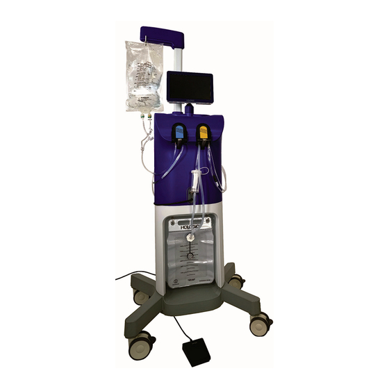
Fluid Bags (not included) containing hypotonic, isotonic, ionic and non-ionic distention fluids hang from the Fluid Bag Hooks located on the IV pole at the top of the Fluent Pro Fluid Management System. Each Fluid Bag Hook can support up to three (3) liters of fluid. Hang only a single Fluid Bag on the Fluid Bag Hooks at a time. -
Page 18: Figure 3: System Launch Screen
Fluent Pro Fluid Management System 1.3.3.2.1 Touchscreen User Interface Use the Touchscreen User Interface to configure and view system information, set the deficit limit, prime the system, and make other adjustments as needed. The Touchscreen prompts perform initial setup tasks (such as Hang Fluid Bag) and displays when the task has been completed. -
Page 19: Figure 4: System Settings Screen
Fluent Pro Fluid Management System 1.3.3.3.2 System Settings Screen Figure 4: System Settings Screen 1.3.3.3.3 System Setup Screen Figure 5: System Setup Screen English Introduction... -
Page 20: Figure 6: System Confirmation Screen
Fluent Pro Fluid Management System 1.3.3.3.4 System Confirmation Screen Figure 6: System Confirmation Screen 1.3.3.3.5 Procedure Screen Figure 7: Procedure Screen Introduction English... - Page 21 Power Cord Port The Power Cord Port is located on the rear of the Fluent Pro Fluid Management System. The Power Cord attaches to the Power Cord Port. When the system is not in use, wrap the Power Cord around the Cord Wrap on the rear of the system.
-
Page 22: Figure 8: 360° Handle
Foot Pedal Basket The Foot Pedal Basket hangs on the rear of the Fluent Pro Fluid Management System. It is used to store the Foot Pedal when not in use. Do not place heavy items in the Foot Pedal Basket. The maximum recommended weight is 10 pounds. -
Page 23: Fluent Pro Procedure Kit Components
Figure 9a: Carton Components Figure 9b: Tray Components Figure 9c: Waste Bag WARNING! Fluent Pro Procedure Kits are single use disposables. Do not re-use or reprocess any of the components contained within the single-use Procedure Kit. 1.3.4.1 Fluent Pro In-FloPak The In-FloPak pulls clean fluid from the Fluid Bag. - Page 24 The non-sterile Waste Bag is designed to capture waste fluid from hysteroscopic procedures. The Waste Bag hangs on the Waste Bag Hooks at the bottom of the Fluent Pro Fluid Management System. Hang only a single Waste Bag on the Waste Bag Hooks at a time. Hanging more than one bag may impact fluid deficit accuracy.
-
Page 25: Procedure Setup
Procedure Setup... - Page 26 This page is intentionally left blank...
-
Page 27: Moving The System
Fluent Pro Fluid Management System Procedure Setup Moving the System 2.1.1 Before moving the system from one location to another, ensure the system is in transport position: 2.1.2 The Power Cord is unplugged from the main outlet and wrapped around the cord wrap on the rear of the system. -
Page 28: Connecting The Power Cord
Fluent Pro Fluid Management System Caution! Only use the Handle to move or position the Fluent Pro Fluid Management System. Do not pull or push the system with the IV pole or Touchscreen Monitor. Caution! Do not lean on the Handle. Leaning may cause the system to tip. -
Page 29: Turning On The Fluent Pro Fluid Management System
Fluent Pro Fluid Management System Turning on the Fluent Pro Fluid Management System Press the Power Button on the top of the system to power on the system. The system performs a setup routine and then displays the System Launch screen. The Power Button will illuminate green when the system is on. -
Page 30: Setup System
Section 3.5.5 for details. • Service Mode: This function is password protected and is intended for Hologic Trained professionals only. To enter Service Mode, touch the ‘SERVICE MODE’ icon. For details on the setup and operation of the hysteroscope, refer to the hysteroscope’s Instructions for Use. -
Page 31: Hang Fluid Bag
2.7.2.2 The Fluent Pro Fluid Management System does not need to be powered on to hang the Fluid Bags. If the system is on, then follow the prompts. The system will detect and display a ‘... -
Page 32: Figure 19A: Carton And Tray
Set the non-sterile Waste Bag aside. Figure 20: Waste Bag 2.7.3.3 Peel back the sterile cover of the Fluent Pro Flo-Pak Kit. Figure 21: Peel Back Sterile Cover 2.7.3.4 While maintaining sterile technique, place the In-FloPak and Out-FloPak onto a sterile surface. -
Page 33: Hang Waste Bag
Fluent Pro Fluid Management System Figure 22a: Out-FloPak connections Figure 22b: In-FloPak connections Hang Waste Bag 2.7.4 Hang the new Waste Bag evenly on the Waste Bag Hooks to begin any new procedure. The system will detect and display a‘... -
Page 34: Install In-Flopak
Install In-FloPak 2.7.5 WARNING! For your own safety and that of your patient, use only Fluent Pro accessories referenced in Table 9: Disposables and Accessories. 2.7.5.1 Depress the In-FloPak Lever and slide the In-FloPak over the triangular shaft. While releasing the Lever, ensure the In-FloPak is flush with front of the console. -
Page 35: Install Out-Flopak
Fluent Pro Fluid Management System Install Out-FloPak 2.7.6 Out-FloPak Lever and slide the Out-FloPak over the triangular shaft. While releasing the Lever, ensure the Out-FloPak is flush with the front of the console. The system will detect and display a ‘... -
Page 36: Figure 28: Connect Waste Bag Connector
Fluent Pro Fluid Management System 2.7.6.3 Secure the Out-FloPak Waste Bag Connector onto the Waste Bag by rotating clockwise. Figure 28: Connect Waste Bag Connector 2.7.6.4 Connect the light cord and the camera to the hysteroscope. Touch ‘NEXT’ on the Touchscreen 2.7.6.5... -
Page 37: Figure 30: Confirmation Screen
Fluent Pro Fluid Management System Touch the ‘NEXT’ icon to proceed. 2.7.6.7 2.7.6.8 The Confirmation screen is then displayed. Figure 30: Confirmation Screen 2.7.6.9 The displayed steps will not be automatically detected and will need to be manually confirmed by touching the blue ‘CONFIRM’... -
Page 38: Priming The System
Begin each procedure with a new, full Fluid Bag. Priming the system runs the pump for approximately one (1) minute to purge air from the tubing and calibrate the hysteroscope. 2.7.7.2 Before priming, make sure that the Fluent Pro In-FloPak and Fluent Pro Out-FloPak are properly connected as described in Section 2.7: Setup System. 2.7.7.3 The system should be primed at the beginning of a case. -
Page 39: Figure 34: Open Inflow Stopcock And Unclamp Inflow Tubing
Fluent Pro Fluid Management System 2.7.7.4.2 Open the inflow stopcock and unclamp the inflow tubing clamp. Figure 34: Open Inflow Stopcock and Unclamp Inflow Tubing 2.7.7.4.3 Direct priming fluid into a basin or Under-Buttocks Drape (UBD). Figure 35: Direct Priming Fluid into UBD 2.7.7.4.4... -
Page 40: Figure 36: Initial Prime Screen
Fluent Pro Fluid Management System 2.7.7.4.5 Touch the ‘PRIME’ icon on the Touchscreen. Figure 36: Initial Prime Screen 2.7.7.4.6 The system will perform an air purge and hysteroscope calibration. Figure 37: Air Purge Screen Procedure Setup English... -
Page 41: Priming Pause
Fluent Pro Fluid Management System Figure 38: Hysteroscope Calibration Screen Priming Pause 2.7.8 2.7.8.1.1 To stop priming at any time, touch the ‘PAUSE’ icon. The End Priming Screen is displayed. Figure 39: End Priming Screen English Procedure Setup... -
Page 42: Figure 40: Priming Paused Screen
Fluent Pro Fluid Management System 2.7.8.1.2 To end priming touch ‘YES’. To continue priming touch ‘NO’ to return to the Priming Paused screen. Figure 40: Priming Paused Screen To continue priming after pause, press ‘REPRIME’. When priming is resumed after pausing, the 2.7.8.1.3... -
Page 43: How To Reprime
Fluent Pro Fluid Management System Select the ‘NEXT’ icon. The Procedure screen will be displayed. 2.7.8.5 Figure 42: Procedure Screen How to Reprime 2.7.9 2.7.9.1 Touch the ‘CHANGE/REPRIME’ icon. The system will pause, and the System Tab will display the Reprime and Change Scope Confirmation screen. - Page 44 This page is intentionally left blank...
-
Page 45: During Procedure
During Procedure... - Page 46 This page is intentionally left blank...
-
Page 47: Adjusting The Deficit
Fluent Pro Fluid Management System During Procedure Figure 44: Procedure Screen Adjusting the Deficit Limit 3.1.1 About Deficit Limits 3.1.1.1 The deficit is the total amount of fluid left in the patient or unaccounted for otherwise. 3.1.1.2 The default Deficit Limit at the start of a new procedure is set to 750 mL. -
Page 48: Zeroing The Deficit
Fluent Pro Fluid Management System 3.1.2 Perform the following steps to adjust the Deficit Limit as necessary. 3.1.2.1 Touch the ‘CHANGE LIMIT’ icon on the System tab on the Procedure screen. Figure 45: Change Deficit Limit screen 3.1.2.2 To adjust the Deficit Limit in increments of 50 mL, touch the Down ‘(-)’ or Up ‘(+)’ icons. -
Page 49: Adjusting The Suction
Fluent Pro Fluid Management System troubleshooting in Section 5 for details. Adjusting the Suction Settings 3.4.1 About Suction Settings for the MyoSure TRD, Outflow Channel and Under-Buttocks Drape (UBD) 3.4.1.1 The default Suction Setting at the start of a new procedure is Low. -
Page 50: Figure 47: Change Scope Screen
Ensure the foot pedal is placed in a location that is accessible to the physician. 3.5.4.3 The MyoSure TRD cannot be operated when the Fluent Pro Fluid Management System is paused. 3.5.4.4 Refer to the MyoSure TRD Instructions for Use for more information on how to use the MyoSure TRD. -
Page 51: Figure 48: Ready To Prime Screen
Fluent Pro Fluid Management System Touch the ‘CHANGE SCOPE’ icon. The Ready to Prime screen will appear. 3.5.6.2 Figure 48: Ready to Prime Screen 3.5.6.3 Direct reprime fluid the Under-Buttocks Drape (UBD). 3.5.6.4 Before beginning reprime, ensure Fluid Bag has at least 200mL of fluid to complete the reprime process. If there is not enough fluid, replace the Fluid Bag with a new, full Fluid Bag. -
Page 52: Ending The Procedure
Fluent Pro Fluid Management System Touch the ‘NEXT’ icon to continue. 3.5.6.8 3.5.6.9 Refer to the hysteroscope Instructions for Use for complete instructions on the use and operation of the hysteroscope, including warnings and cautions. Caution! Failure to reprime after changing hysteroscope may affect uterine pressure control. -
Page 53: Last Procedure Data
WARNING! Do not remove the Fluent Pro Out-FloPak and Waste Bag if you want to allow suction to continue to run to remove excess fluid from the Under-Buttocks Drape (UBD) to accurately reflect the deficit. If the Fluid Bag or Waste Bag are removed at this time, the deficit will need to be calculated manually. -
Page 54: Replacing Components
Depending on the procedure, you may need to replace disposable components. This Section provides information and instructions for replacing the Fluid Bag, Waste Bag, and Tissue Trap while using the Fluent Pro System. To alert you of changes, the Fluent Pro Fluid Management System Fluid Bag Hooks and Waste Bag Hooks contain built-in scales, and the system will prompt you if you need to take action. -
Page 55: Waste Bag
Fluent Pro Fluid Management System 3.8.1.6.2.1 Remove the non-active empty Fluid Bag and unspike. 3.8.1.6.2.2 Hang a new Fluid Bag on the vacant Fluid Bag Hook. 3.8.1.6.2.3 Spike the new Fluid bag. 3.8.1.6.2.4 Unclamp the Fluid bag tubing on the hanging full Fluid Bag when ready. -
Page 56: Figure 54: Screw Waste Bag Cap Onto Waste Bag
Fluent Pro Fluid Management System 3.8.2.4 Screw the Waste Bag cap onto the Waste Bag by rotating the cap clockwise. Figure 54: Screw Waste Bag Cap onto Waste Bag 3.8.2.5 Remove the full Waste Bag from the Waste Bag Hooks and discard the Waste Bag according to facility protocols. -
Page 57: Tissue Trap
Fluent Pro Fluid Management System 3.8.2.8 If ‘Missing Waste Bag’ error is displayed, ensure the Waste Bag is installed properly on the Hooks, touch the ‘CLEAR’ icon and continue with the procedure. Replacing the Tissue Trap 3.8.3 3.8.3.1 If the tissue trap appears to be full, by expanding outside of the internal basket, the tissue trap is near capacity and must be changed. - Page 58 This page is intentionally left blank...
-
Page 59: After Procedure
After Procedure... - Page 60 This page is intentionally left blank...
-
Page 61: Disassembly And Disposal
Disassembly and Disposal WARNING! Fluent Pro Procedure Kits are single use disposables. Do not re-use or reprocess any of the components contained within the single- use Procedure Kit. Note: Comply with your facility’s disposal and hygiene rules when disposing of Fluent Pro Procedure Kits, the Tissue Trap, fluid collected, and the Waste Bag. -
Page 62: Dispose Of Waste Materials
Fluent Pro Fluid Management System Dispose of Waste Materials 4.1.3 4.1.3.1 Remove the Waste Bag Connector from the Waste Bag by rotating the connector counterclockwise. Figure 59: Remove Waste Bag Connector WARNING! Do not place excessive force or weight on the Waste Bag Hooks. Doing so may result in an inaccurate fluid deficit value, causing risk to patient safety. -
Page 63: Disassemble The
Fluent Pro Fluid Management System 4.1.3.3 Remove the full Waste Bag from the Waste Bag Hooks and discard the Waste Bag according to facility protocols. Figure 61: Remove Full Waste Bag Disassemble the Under-Buttocks Drape (UBD) 4.1.4 4.1.4.1 Disconnect the Out-FloPak tubing yellow connector from the Under-Buttocks Drape (UBD) Port. -
Page 64: Shutdown And 4.2 Cleaning The Fluentp
4.3.3 Transport the system using the 360° Handle. Caution! Only use the Handle to move or position the Fluent Pro Fluid Management System. Do not pull or push the system with the IV pole or Touchscreen Monitor. WARNING! Do not place excessive force or weight on the Fluid Bag Hooks. Doing so may result in an inaccurate fluid deficit value, causing risk to patient safety. - Page 65 Fluent Pro Fluid Management System WARNING! Do not place excessive force or weight on the Waste Bag Hooks. Doing so may result in an inaccurate fluid deficit value, causing risk to patient safety. English After Procedure...
- Page 66 This page is intentionally left blank...
-
Page 67: Troubleshooting
Troubleshooting... - Page 68 This page is intentionally left blank...
-
Page 69: Help
Fluent Pro Fluid Management System Troubleshooting Help Touch the ‘HELP’ icon at any time to access the help menu and display step-by-step instructions on the Touchscreen. The ‘HELP’ icon is located at the bottom of the Launch screen, Setup screen, Confirmation screen and Procedure screen. -
Page 70: Help With Setup
Fluent Pro Fluid Management System Help with Setup 5.1.2 5.1.2.1 On the Setup and Additional Setup Help screen menu, select the desired topic to display the Help screen for that step. Figure 65a: Setup Help Menu Figure 65b: Additional Setup Help Menu 5.1.2.2... -
Page 71: Help During The
Fluent Pro Fluid Management System Help During the Procedure 5.1.4 5.1.4.1 On the Procedure Running Help screen menu select the desired topic to display the Help screen for that step. If a submenu appears, select a subtopic from the menu to display the Help screen. -
Page 72: Troubleshooting
Fluent Pro Fluid Management System Resume Procedure (After Power Loss or Shutdown) If the system is shutdown or a power loss occurs prior to completion of a procedure, the option of resuming the last procedure will be available. Upon startup, the System Restarted screen is displayed. This screen displays last procedure data, including Current Deficit, Fluid In and Cutting Time. -
Page 73: Loss Of Suction 5.3.3 Inadequate S 5.3.4 Poor Visibility
Power Loss 5.3.8 5.3.8.1 If the Fluent Pro Fluid Management System powers down or loses power unexpectedly, wait at least 15 seconds then power on the system and follow on-screen prompts. To resume the previous procedure, refer to Section 5.2. -
Page 74: System Frozen
WARNING! When replacing a fuse, use only type T5AH, 250V fuses. 5.3.8.2.1 The Power Cord is properly connected to both the Power Port on the rear of the Fluent Pro Fluid Management System and to a wall outlet. 5.3.8.2.2 The wall outlet has power. Test the outlet by plugging in another device to ensure it is working properly. -
Page 75: Limit
Fluent Pro Fluid Management System GUI Notifications and Alerts 5.3.10 Notifications and Troubleshooting (Screen Flashing Yellow and Orange) 5.3.10.1 Table 1: Real-time Display, Notifications and Troubleshooting Notification Message Description Resolution Fluid Bag(s) Low Volume in Fluid Bag is less than 500mL Add Fluid Bag with volume above 500mL. -
Page 76: Table 2: Real-Time Display, Alerts And Troubleshooting
Fluent Pro Fluid Management System Alerts and Troubleshooting (screen flashing Red and Pink) 5.3.10.2 Table 2: Real-time Display, Alerts and Troubleshooting Alert Message Description Resolution Waste Bag Full Volume in Waste Bag has reached 6000mL Remove full Waste Bag and replace with a new empty Waste Bag. -
Page 77: Figure 70: System Fault Screen
Fluent Pro Fluid Management System System Faults 5.3.10.3 If a System Fault occurs at any point during a procedure, the System Fault screen is displayed, as shown below. This screen displays information regarding the fault, as well as the last procedure data, including deficit, total fluid in and cutting time. -
Page 78: Table 3: Real-Time Display, System Faults
Fluent Pro Fluid Management System 5.3.10.3.1 System Fault Messages Table 3: Real-time Display, System Faults Fault Message(s) Resolution Turn system off. Allow 5 minutes for system to cool down before turning the system on. Temperature Fault 1-4 If problem persists, call Technical Support. -
Page 79: Supplementary Information
Supplementary Information... - Page 80 This page is intentionally left blank...
-
Page 81: Annual Inspection
Fluent Pro Fluid Management System Supplementary Information Annual Inspection The inspections detailed below are required to be performed annually to assess system functionality and technical safety. Regular inspections will assist in early detection of possible malfunctions. This helps maintain the system and increases its safety and service life. -
Page 82: Figure 72: Scale Calibration Check, Part 1 Screen
Fluent Pro Fluid Management System Touch the ‘START’ icon. The Scale Calibration Check Part 1: Zero the Scales screen is displayed. 6.1.1.4 6.1.1.5 Remove everything from the Fluid Hooks and Waste Bag Hooks. Figure 72: Scale Calibration Check, Part 1 Screen 6.1.1.6... -
Page 83: Figure 74: Scale Calibration Check, Part 2 Screen
Fluent Pro Fluid Management System Once scales are zeroed, touch the ‘NEXT’ icon. The Scale Calibration Check Part 2: Check Weight Readings 6.1.1.8 screen is displayed. Figure 74: Scale Calibration Check, Part 2 Screen 6.1.1.9 Hang a weight on one of the Hooks. The weight should read +/-5%. -
Page 84: Alibration Check
Fluent Pro Fluid Management System Pressure Calibration Check 6.1.2 The Pressure Calibration Check tests the system's pressure sensor. This test requires a Fluid Bag, an In-FloPak and an empty container to collect fluid. 6.1.2.1 Press the Power Button on the top of the system to power on the system. -
Page 85: Figure 77: Pressure Calibration Check Steps, Part 2
Fluent Pro Fluid Management System Press ‘NEXT STEPS’ to continue setup including placement of the container and opening the Fluid Bag 6.1.2.5 Clamps. Figure 77: Pressure Calibration Check Steps, Part 2 Press ‘NEXT’ to perform pressure check. 6.1.2.6 Follow prompts and press ‘START PURGE’ to start the purge of air. -
Page 86: Figure 79: Stop Purge For Pressure Calibration Check
Fluent Pro Fluid Management System Press ‘STOP PURGE’ once the tube is filled with fluid and there are no air bubbles remaining. 6.1.2.8 Figure 79: Stop Purge for Pressure Calibration Check 6.1.2.9 Remove the end of the Inflow Tube from the container and hold it even with the tip of the Fluid Bag bracket. -
Page 87: Technical Specifications
Fluent Pro Fluid Management System Technical Specifications Table 4: Technical Specifications Item Specification Model or type designation FLT-200 Mains voltage range [V] 100-240 VAC Supply Frequency Range [Hz] 50-60Hz Fuse designation T5AH, 250 V fuses Mode of Operation Non-continuous (Max Duty: 60 minutes ON, 30 minutes IDLE) -
Page 88: Power Cord Safety
The Fluent Pro Fluid Management System is intended for use in the electromagnetic environment specified below. The customer or the user of the Fluent Pro Fluid Management System should ensure that it is used in such an environment. Non-observance of the instructions listed in this manual can lead to damage or malfunction of the system. -
Page 89: Table 6: Electromagnetic Immunity Guidance
The Fluent Pro Fluid Management System is intended for use in the electromagnetic environment specified below. The customer or the user of the Fluent Pro Fluid Management System should ensure that it is used in such an environment. Non-observance of the instructions listed in this manual can lead to damage or malfunction of the system. - Page 90 RF transmitters, an electromagnetic site survey should be considered. If the measured field strength in the location in which the Fluent Pro Fluid Management System is used exceeds the applicable compliance level above, the Fluent Pro Fluid Management System should be observed to verify normal operation.
-
Page 91: Emissions Guidance And M Immunity Guidance And M Separation Distances
Recommended Separation Distances 6.4.3 The Fluent Pro Fluid Management System is intended for use in an electromagnetic environment in which radiated RF disturbances are controlled. The customer or the user of the Fluent Pro Fluid Management System can help prevent... -
Page 92: Console Disposal
Procedure Kit Storage The Fluent Pro Procedure Kit should be stored at room temperature away from moisture and direct heat. Do not use after expiration date. Procedure Kit Disposal The used disposable device must be treated as biohazardous waste and disposed of according to standard practices of the hospital or surgery center where the procedure took place. -
Page 93: Figure 81: Preventative Maintenance Due Date
6.9.3 Contact Hologic Technical Support for proper disposal of any part of the Fluent Pro Fluid Management System if it fails to operate as intended. If product is to be returned to Hologic for any reason, Technical Support will issue a Returned Materials Authorization (RMA) number and biohazard kit if applicable. -
Page 94: Nformation
Complaints Reporting: 6.9.4 Report any complaints or problems with the quality, reliability, safety, or performance of this product to Hologic. If the device has caused or added to patient injury, immediately report the incident to Hologic Authorized Representative and Competent authority of the respective member state or country. The Competent Authorities for medical devices are usually the individual Member States’... - Page 95 (WEEE) is required. Hologic, Fluent, MyoSure, In-FloPak, Out-FloPak and associated logos are registered trademarks of Hologic, Inc. and/or its subsidiaries in the United States and other countries. All other trademarks, registered trademarks, and product names are the property of their respective owners.
-
Page 96: Glossary
Fluent Pro Fluid Management System Glossary 6.11 Term Definitions Circumstances (e.g., age, pregnancy, certain illness, medication) prohibiting the use of an otherwise indicated Contraindication measure (contrary to an indication) Deficit The total amount of fluid left in the patient or unaccounted for otherwise. The fluid left in the patient must be monitored. - Page 98 Hologic, Inc. 250 Campus Drive Marlborough, MA 01752 USA 1-800-422-9892 www.hologic.com Patents: http://hologic.com/patentinformation MAN-11714-001 Rev. 001 09/2024...
Need help?
Do you have a question about the Fluent Pro and is the answer not in the manual?
Questions and answers