
Subscribe to Our Youtube Channel
Related Manuals for Hologic Faxitron CT


Summary of Contents for Hologic Faxitron CT
- Page 1 User’s Manual ® from Hologic Document #: 5081-9544 Revision: 002 Issued: March 2020...
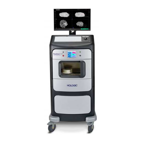
- Page 2 Intended Use The Faxitron CT is a Cabinet x-ray system that is used to provide two and three dimensional digital x-ray images of harvested specimens from various anatomical regions in order to provide rapid verification that the correct tissue has been excised during the biopsy procedure.
-
Page 3: Table Of Contents
3.1.0 Calibration Overview 3.1.1 Image Caibration 3.1.2 Geometric Calibration 3.1.3 Uniformity Calibration SECTION 4: Quick Start - Basic Operation of the Faxitron CT 4.1.0 Quick Start 4.2.0 Shutdown SECTION 5: Faxitron CT Software Operation 5.0.0 Overview of Faxitron CT Software 5.1.0... - Page 4 8.7.0 Safety Interlocks and Indicators 8.8.0 ACR Phantom Test 8.9.0 Radiation Survey 8.10.0 3D Uniformity Test 8.11.0 3D Resolution Test 8-10 Periodic Maintenance Record 8-12 SECTION 9: Revision Table Revision Table FAXITRON CT USER MANUAL | HOLOGIC | REVISION 002...
-
Page 5: Introduction
SECTION 1 Introduction FAXITRON CT USER MANUAL | HOLOGIC | REVISION 002... -
Page 6: Warning And Caution Symbols In This Manual
Faxitron CT hardware and the Software, both developed by Introduction Faxitron Bioptics LLC. The user must first setup the hardware, then initiate the Faxitron CT Software. At a minimum, please review the required setup and safety procedures in this manual before attempting to operate the system. -
Page 7: Warning And Caution Symbols On Labels
Date of Manufacture Caution—Radiation (X-Rays Produced) Caution - Potentially infectious materials Warning Electricity Caution Follow or consult instructions for use This system transmits radio frequency (RF) energy (non-ionizing radiation) Catalog number Serial number FAXITRON CT USER MANUAL | HOLOGIC | REVISION 002... -
Page 8: Product Labels
SECTION Introduction Label A – Standard and Canadian Versions 1.2.0 Product Labels Figure 1.3.1 Warning and Safety Labels Label B Label C FAXITRON CT USER MANUAL | HOLOGIC | REVISION 002... - Page 9 SECTION Introduction Label D – Standard and Canadian Version 1.2.0 Product Labels Figure 1.3.1 (Continued) Warning and Safety Labels Label E Label F FAXITRON CT USER MANUAL | HOLOGIC | REVISION 002...
- Page 10 SECTION Introduction Label G 1.2.0 Product Labels Figure 1.3.1 (Continued) Warning and Safety Labels Label H Label K Label L FAXITRON CT USER MANUAL | HOLOGIC | REVISION 002...
- Page 11 SECTION Introduction Barcode, Identification and Compliance Label - Mobile System 120VAC 1.2.0 Product Labels Figure 1.3.1 (Continued) Warning and Safety Labels Barcode, Identification and Compliance Label - Mobile System 230VAC FAXITRON CT USER MANUAL | HOLOGIC | REVISION 002...
- Page 12 Label D (Inside Door) Label G (Inside Door) Label F (Inside Door) Label C (Chamber Floor) Label G used on the inside for the Tube, Camera and Lower Rear Cover Interlock. FAXITRON CT USER MANUAL | HOLOGIC | REVISION 002...
- Page 13 SECTION Introduction Label H Front labels same as shown on previous page Compliance and Label K Identification Label Label L FAXITRON CT USER MANUAL | HOLOGIC | REVISION 002...
-
Page 14: Installation And Set-Up
SECTION 2 Installation and Set-up FAXITRON CT USER MANUAL | HOLOGIC | REVISION 002... - Page 15 Interoperable Connections The Faxitron CT is capable of operating as a standalone device without any input or output to other devices. Images can be captured, stored and reviewed directly on the system.
- Page 16 Set up additional users with local administration rights to ensure the software runs correctly. Work with the Faxitron / Hologic team during installation to make sure the system is configured properly.
-
Page 17: Faxitron Ct Specimen System Setup
Location & Building Requirements The Faxitron CT system has ventilation and the power entry connector is at the rear of the cabinet. Leave at least 6” (15cm) of clear space behind the unit when installed to allow the air to flow and give the user access to disconnect the power cord. -
Page 18: Specifications
24 inch or better monitor with at min 1280x1024 resolution • 6x USB Slots including 2x USB 3.0 • 2x Ethernet ports including one with 9000 bytes jumbo packet • Windows 10 OS based PC • Internet Browser FAXITRON CT USER MANUAL | HOLOGIC | REVISION 002... - Page 19 Dynamic Range: 76dB DQE (@0 lp/mm, RQA5): 70% Scintillator: Medical grade columnar cesium-iodide CsI(Tl) EXTERIOR DIMENSIONS (Approximate) inches Height Width Depth COMPARTMENT INTERIOR DIMENSIONS (Approximate) inches Height Width Depth WEIGHT (Approximate) Shipping FAXITRON CT USER MANUAL | HOLOGIC | REVISION 002...
- Page 20 SECTION Installation and Setup 180cm 70" 70cm 65cm 27" 25" FAXITRON CT USER MANUAL | HOLOGIC | REVISION 002...
- Page 21 SECTION 3 Calibration FAXITRON CT USER MANUAL | HOLOGIC | REVISION 002...
-
Page 22: Camera Calibration
This calibration requires the acquisition of reference images. On first installation the system should be allowed to reach the ambient room temperature and a full calibration performed. There are 3 calibrations for Faxitron CT which should be performed at each interval shown Image Calibration Daily... -
Page 23: Geometric Calibration
If the 3D image quality degrades at any time, visible rings in the image for example, conduct a geometric calibration. Go to the main screen and click on the Calibrate button, as before, and then select Geometric Calibration. FAXITRON CT USER MANUAL | HOLOGIC | REVISION 002... - Page 24 Check the box to confirm the Phantom is placed and proceed by clicking Start. The calibration will begin taking a full 360-degree image of the phantom which takes up to four minutes. FAXITRON CT USER MANUAL | HOLOGIC | REVISION 002...
-
Page 25: Uniformity Calibration
Check the box to confirm the Phantom is placed and proceed by clicking Start. As before the calibration will begin taking a full 360-degree image of the phantom which takes up to four minutes. FAXITRON CT USER MANUAL | HOLOGIC | REVISION 002... -
Page 26: Quick Start Basic Operation Of The Faxitron Ct
SECTION 4 Quick Start Basic Operation of the Faxitron CT FAXITRON CT USER MANUAL | HOLOGIC | REVISION 002... - Page 27 On / Off Button • Turn the power on to the Faxitron CT System by switching the mains power switch located on the back of the system above the power cord outlet. Switch to “1”...
- Page 28 • Close the chamber door. Figure 4.1.2 Faxitron CT Consumable Tray • Select the “Start Procedure” from the main screen Inner Ring Figure 4.1.3 Select Procedure Screen FAXITRON CT USER MANUAL | HOLOGIC | REVISION 002...
- Page 29 • Type in the name and ID for the Patient. The starred (asterisk) boxes must have a value in them. For a Patient you will also need an accession number and laterality. Figure 4.1.5 Sample / Patient Data Screen FAXITRON CT USER MANUAL | HOLOGIC | REVISION 002...
- Page 30 Save to PACS • The button in the bottom left will show the send status. Do not shut down the system while the Figure 4.1.10 images are still sending. Sending to PACS FAXITRON CT USER MANUAL | HOLOGIC | REVISION 002...
- Page 31 • As before do not shut down the system while the images are still sending. (Note: A backup of all images are stored on the local drive) For more information on adjusting the image, reviewing and save options, see Section 5. FAXITRON CT USER MANUAL | HOLOGIC | REVISION 002...
-
Page 32: Shutdown
Shutdown Procedure 4.2.0 Shutdown The are 2 options to shutdown Faxitron CT systems: Press and hold the ON/OFF button on the front of the system until a "Beep" is heard. This will shut down the software, computer and system. Figure 4.2.1... -
Page 33: Faxitron Ct Software Operation
SECTION 5 Faxitron CT Software Operation FAXITRON CT USER MANUAL | HOLOGIC | REVISION 002... -
Page 34: Overview Of Faxitron Ct Software
Faxitron CT Software is a complete image acquisition and processing package, designed 5.0.0 exclusively to work with the Faxitron CT system. In addition to the acquisition and processing Overview of functions, the software offers an extensive database module that allows user control and Faxitron CT maintenance of image archiving, storage, filing and retrieval. -
Page 35: Patient Data
Accept to proceed to image acquisition. A patient’s information can be imported to the local Database from the Modality Work List by selecting Save to Database. FAXITRON CT USER MANUAL | HOLOGIC | REVISION 002... -
Page 36: Continue With Current Patient
If a Patient has previously been loaded, you can click on this button to Continue with Current Patient procedure. The Patient Information editor will open, as shown above, and you can continue as before. FAXITRON CT USER MANUAL | HOLOGIC | REVISION 002... -
Page 37: Manual Entry
Database from the Work List using the Save to Database button, as described in section 5.3.1. The software allows the user to sort the data by selecting the column title. FAXITRON CT USER MANUAL | HOLOGIC | REVISION 002... -
Page 38: Patient Information
Patient Data icon again. 5.5.0 Image Acquisition See Section 4 Quick Start for information on how to place the specimen into the system and acquire an Image. Figure 5.51 Start X-Ray Button FAXITRON CT USER MANUAL | HOLOGIC | REVISION 002... -
Page 39: Image Screen - 2D Mode
The bottom right image is a 3D rendering of the reconstruction volume. All other views are 3D Mode reconstructed slice views of the specimen. Figure 5.6.2 3D Image Screen The following sections outline the manipulation of the images. FAXITRON CT USER MANUAL | HOLOGIC | REVISION 002... -
Page 40: Image Tools
The system will be idle (in Standby) during the processing. Once completed the button will stay depressed/active. The user can undo the process by pressing the button again. FAXITRON CT USER MANUAL | HOLOGIC | REVISION 002... -
Page 41: Window Level
By clicking Link Contrast all the views will match the selected settings. The user may also restore the Original Contrast by pressing the Original Contrast button. Click OK or Cancel to exit. FAXITRON CT USER MANUAL | HOLOGIC | REVISION 002... -
Page 42: Dynamic Zoom
Zoom 1.0x is traditionally called “Full Resolution” as it brings the image to a 1-1 view with the monitor resolution. The user can also type in a zoom value and click Set Click OK or Cancel to exit. FAXITRON CT USER MANUAL | HOLOGIC | REVISION 002 5-10... -
Page 43: Annotations
Annotations The button shown will open the annotation tools. Figure 5.7.6 User Annotations in the Faxitron CT Software allows one to apply a transparent Annotations icon graphic “overlay” commonly call “annotations” to an image. These annotations take the form of text, lines, “free form” lines (Bezier curves), arrows, ellipse and boxes. This allows additional information and “markers”... - Page 44 The Toggle Annotations button, shown in Figure 5.7.9, allows users to quickly Show/Hide Annotations toggle annotations on and off. By default, the annotations will be toggled on. The button is located in the right-side menu near the upper right corner. FAXITRON CT USER MANUAL | HOLOGIC | REVISION 002 5-12...
-
Page 45: Pacs Store (Save To Pacs)
Image Info Icon & Display Back Figure 5.7.12 The button shown in Figure 5.4.13 exits the image acquisition mode and returns to Back to Home Menu icon the Main Menu screen. FAXITRON CT USER MANUAL | HOLOGIC | REVISION 002 5-13... - Page 46 The circular arrow button in the bottom right is the view reset button, which will reposition the specimen back to its original view. Figure 5.8.2 Faxitron CT 3D view Estimated volume of the specimen is displayed at the top of this view in cubic centimeters. FAXITRON CT USER MANUAL | HOLOGIC | REVISION 002 5-14...
-
Page 47: Specimen Orientation
The posterior should be on the foam with caudal (inferior) pointing towards the front of the system and the marker on the foam tray as shown below. Figure 5.8.3 Specimen Orientation This will produce the image shown below, Figure 5.8.4 Faxitron CT Display FAXITRON CT USER MANUAL | HOLOGIC | REVISION 002 5-15... - Page 48 View 1 is Cranial Caudal (CC) Orientation Figure 5.8.5 CC View View 2 in Medial Lateral (ML) Figure 5.8.6 ML View View 3 is Anterior Posterior (AP) Figure 5.8.7 AP View FAXITRON CT USER MANUAL | HOLOGIC | REVISION 002 5-16...
- Page 49 (Anterior Posterior). Figure 5.8.9 Faxitron CT Slice View This coloring of the Cube is similar to how specimens are inked to show their orientation. FAXITRON CT USER MANUAL | HOLOGIC | REVISION 002 5-17...
- Page 50 Orientation Markers Can be displayed in each view to aid 5.8.1 Cont. Specimen Orientation This will display position of the sample relative to the system. Figure 5.8.10 Faxitron CT Orientation Markers FAXITRON CT USER MANUAL | HOLOGIC | REVISION 002 5-18...
-
Page 51: Slice Views
In addition by selecting the line in the other view it can be dragged up or down to move the slice position. This is the same for all 3 axis. FAXITRON CT USER MANUAL | HOLOGIC | REVISION 002 5-19... - Page 52 PLAY button is pressed again. The colored lines in the other 2 views will move in unison to display the corresponding slices in those views. FAXITRON CT USER MANUAL | HOLOGIC | REVISION 002 5-20...
-
Page 53: Mip View
Figure 5.8.14 Faxitron CT MIP View To switch between MIP and SLICE view simply click on the word in the bottom left corner. FAXITRON CT USER MANUAL | HOLOGIC | REVISION 002 5-21... -
Page 54: Hounsfield Units
Fatty Tissue Denser fiberous tissue Figure 5.8.16 Simply place the cursor on the area of intertest to see the Housnfield unit. Below is fatty Denser Tissue A calcification Figure 5.8.17 Calcification FAXITRON CT USER MANUAL | HOLOGIC | REVISION 002 5-22... -
Page 55: Current Patient Image History
List on the lower left, the image list on the lower right and the image preview in the middle. Figure 5.9.2 Image Database To Open an image, select the patient, procedure, the image and then click Open. FAXITRON CT USER MANUAL | HOLOGIC | REVISION 002 5-23... - Page 56 If there are a series of images, simply pick one image in the series and the software will load them. Figure 5.9.5 Browser File System FAXITRON CT USER MANUAL | HOLOGIC | REVISION 002 5-24...
-
Page 57: Dicom / Pacs Functionality
Standard file. Once a software application recognizes the file as a DICOM Standard file it can initiate a DICOM reader and extract the data properly, regardless of the file’s origin. All images on the Faxitron CT are saved in the DICOM standard and transmitted to PACS in that format. -
Page 58: System Settings
These include the following: Default directories Figure 5.11.1 Defualt Directories Viewer settings Figure 5.11.2 Viewer Settings Imager parameters Figure 5.11.3 Image Settings Figure 5.11.4 And Image Enhancement settings Image Enhancement FAXITRON CT USER MANUAL | HOLOGIC | REVISION 002 5-26... -
Page 59: About
Review a simple animation showing how the specimen should be placed • Get the contact information for support • Remote Connect the system to the Hologic team • Exit to Windows Figure 5.13.1 Help Dialog Box FAXITRON CT USER MANUAL | HOLOGIC | REVISION 002 5-27... -
Page 60: Shutdown
To shut down from the software, simply click Shut Down and the entire system will shut down. A message will appear to confirm the system will be shut down. Click Okay to continue and let the system fully power down. Figure 5.14.2 Shutdown Dialog FAXITRON CT USER MANUAL | HOLOGIC | REVISION 002 5-28... -
Page 61: Compliance Requirements And Safety Measure
SECTION 6 Compliance Requirements and Safety Measure FAXITRON CT USER MANUAL | HOLOGIC | REVISION 002... -
Page 62: Compliance Requirements And Safety Measure
X-Ray Generation Indicators The Faxitron CT has an X-Ray On indicator light on the front panel, on the touch panel and graphical user interface, plus it produces an audible tone when generating X-Rays. Power Ratings 120VAC 60Hz or 230VAC 50Hz 700W Max. -
Page 63: Service & Troubleshooting
SECTION 7 Service and Troubleshooting FAXITRON CT USER MANUAL | HOLOGIC | REVISION 002... -
Page 64: Service & Troubleshooting
Slower than normal operation and/or network connection • Suspicious pop-ups or home page changed in internet browser • Password(s) no longer working • Unidentified programs in start menu or system tray • Missing, corrupt or altered data FAXITRON CT USER MANUAL | HOLOGIC | REVISION 002... -
Page 65: Schedule Of Maintenance
SECTION 8 Schedule of Maintenance FAXITRON CT USER MANUAL | HOLOGIC | REVISION 002... -
Page 66: Schedule Of Maintenance
SECTION Schedule of Maintenance This document provides a schedule of testing and maintenance for the Faxitron CT. It is 8.0.0 strongly recommended that the maintenance and tests described in this section be performed Maintenance at the intervals of time indicated to ensure that your Faxitron X-Ray generator continues to operate at optimal performance. -
Page 67: Definitions
The firmware is hard coded into the control board so if a firmware update is required, replace the control panel PCB. FAXITRON CT USER MANUAL | HOLOGIC | REVISION 002... -
Page 68: Safety Interlocks And Indicators
7. Verify that the green Start X-Ray software button is on. 8. In 2D mode press the green X-ray button on the touchscreen on the front of the Faxitron CT. The system should begin taking an x-ray exposure. Verify that: •... -
Page 69: Acr Phantom Test
Section, or on an approved form. The user should be familiar with using the Faxitron CT and should know the procedures of taking X-Rays. Go through the setup procedures and make sure that the system is fully calibrated - Image, Geometric and Uniformity. - Page 70 In 3D mode all groups of objects must be clearly visible. Switch the slice view to MIP to make it easier to see all the objects on one plane. Record results on the Periodic Maintenance Record. FAXITRON CT USER MANUAL | HOLOGIC | REVISION 002...
-
Page 71: Radiation Survey
1. All radiation measurements are taken with the radiation Survey Meter no more than 2 inches (5cm) from the surface of the Faxitron CT unit. 2. When recording the radiation measurements, they may need to be multiplied by 0.1 to convert the reading from uSv/hr to mR/hr. - Page 72 (mR) per hour (1.0 µSv/h) at any point 5 centimeters (cm) outside the external surface (*), contact a Faxitron or Hologic representative to discuss repair options. (*) 0.5 mR/h at 5 cm from external surfaces is the upper limit by US FDA CDRH for cabinet x-ray systems.
-
Page 73: 3D Uniformity Test
8.10.0 3D Uniformity Test The user should be familiar with using the Faxitron CT and be familiar with performing a 3D scan. In this procedure, the Uniformity Phantom will be scanned in 3D mode, reconstructed, and measurements performed on the reconstructed data. -
Page 74: Resolution Test
Maintenance 3D Resolution 8.11.0 3D Resolution The user should be familiar with using the Faxitron CT and be familiar with performing a 3D Test scan. In this procedure, the 3D Resolution Phantom will be scanned in 3D mode, reconstructed, and measurements performed on the reconstructed data. - Page 75 Use the cursor to measure the X position on the left side of the width and on the right side and the calculate the difference. 10. This value should be less than 0.4 mm for acceptance. NOTE: If the 3D Resolution Test fails repeat the Geometric Calibration. FAXITRON CT USER MANUAL | HOLOGIC | REVISION 002 8-11...
-
Page 76: Periodic Maintenance Record
If any failed, state the reason and the actions taken to correct the failure. _________________________________________________________________________________ _________________________________________________________________________________ Initials: _____________ Date: ______________ The periodic maintenance identified above was completed by: ____________________________________ Date Completed:_______________ Signature: ______________________________________________ FAXITRON CT USER MANUAL | HOLOGIC | REVISION 002 8-12... - Page 77 ”Stop” button on the Touch Screen, or the physical “Stop” button on the control panel is pressed, • X-ray exposure does not stop immediately when the door is open, or • The Touch Screen does not display “Door Open” any time the chamber door is open. FAXITRON CT USER MANUAL | HOLOGIC | REVISION 002 8-13...
- Page 78 SECTION 9 Revision History FAXITRON CT USER MANUAL | HOLOGIC | REVISION 002...
- Page 79 Initial Production Release Ciaran Purdy See CCB Software sections updated based on final release. 03-20-2020 Revision Updated images in Sections 4 & 5 Alan Mihalko See CCB Updated Section 8 for added clarity FAXITRON CT USER MANUAL | HOLOGIC | REVISION 002...
Need help?
Do you have a question about the Faxitron CT and is the answer not in the manual?
Questions and answers