
Related Manuals for Raycus RFL-A6000D


Summary of Contents for Raycus RFL-A6000D
- Page 1 Fiber Delivered Direct Diode Lasers User Guide RFL-A6000D RFL-A8000D RFL-A10000D RFL-A12000D Wuxi Raycus Fiber Laser Technologies Co., Ltd.
-
Page 2: Table Of Contents
Wuxi Raycus Fiber Laser Technologies Co., Ltd. User Guide of Raycus RFL-A6000D~A12000D CONTENTS SAFETY INFORMATION.......................1 SECURITY LABELS..........................1 LASER SAFETY GRADE........................2 OPTICAL SAFETY..........................2 ELECTRICAL SAFETY.......................... 2 OTHER SAFETY RULES........................3 PRODUCT DESCRIPTION......................3 FEATURES............................3 PACKAGE PARTS..........................4 UNPACKING AND INSPECTION......................4 OPERATION ENVIRONMENT......................4... - Page 3 Wuxi Raycus Fiber Laser Technologies Co., Ltd. User Guide of Raycus RFL-A6000D~A12000D ON MODE............................30 5.1.1 AD ENABLE MODE........................30 5.1.2 EMISSION EXTERNAL CONTROL ENABLE..................30 5.1.3 RED LIGHT CONTROL........................30 5.1.4 PROGRAMMING MODE......................30 REM MODE............................. 31 5.2.1 AD ENABLE MODE........................31 5.2.2...
- Page 4 Wuxi Raycus Fiber Laser Technologies Co., Ltd. User Guide of Raycus RFL-A6000D~A12000D LASER STATUS DISPLAY AREA......................52 ALARM TYPE DISPLAY AREA......................53 PC SOFTWARE OPERATING MODE SELECTION................53 LANGUAGE............................54 AUTHORIZATION (TIME-LIMITED LOCKING)...................55 8.8.1 AUTHORIZATION ON USER MODE....................55 8.8.2 AUTHORIZATION ON AUTHORIZATION MODE................55 ABOUT............................
-
Page 5: Safety Information
User Guide ofRaycus RFL-A6000D~A12000D 1 Safety Information Thank you for choosing Raycus Fiber Delivered Direct Diode Laser. This user manual provides you with important safety, operation, maintenance and other relevant information. Please read the manual carefully before using this product. To ensure safe operation and optimum product operation, please observe the following cautions and warnings as well as other information within this manual. -
Page 6: Laser Safety Grade
Wuxi Raycus Fiber Laser Technologies Co., Ltd. User Guide of Raycus RFL-A6000D~A12000D 1.2 Laser Safety Grade This series of lasers are Class 4 laser instruments. The product emits laser radiation at a wavelength of 915nm or around 915nm, and the average laser power radiated from the fiber delivery cable connector is 6kW~12kW (depending on laser model). -
Page 7: Other Safety Rules
There are no user serviceable parts, equipment or assemblies inside the product. All service and maintenance shall be conducted by a certified Raycus engineer. In order to prevent electric shock, please do not break the seal or uncover the shield. Otherwise, any damage to the device will not be guaranteed. -
Page 8: Package Parts
Once you find that there is an abnormality in the external cabinet, please inform Raycus Company in time to deal with it as soon as possible. Please double check if each listed object is inside the package; and contact Raycus as soon as possible if there are any issues. -
Page 9: Attentions
Wuxi Raycus Fiber Laser Technologies Co., Ltd. User Guide of Raycus RFL-A6000D~A12000D 2.5 Attentions a) Make sure the product is properly grounded before use. b) Make sure that the correct voltage of 380VAC is used. Power supply connection failures will cause irreversible damages the device. -
Page 10: Installation
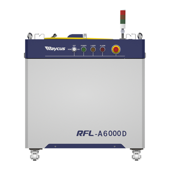
Air conditioning included <360 <400 <450 <500 Operating Ambient 10~40 Temperature (°C) Humidity (%) <70 Storage -10~60 temperature (°C) Cooling method Water cooling 3 Installation 3.1 Dimensions The main body dimensions of RFL-A6000D fiber delivered direct diode laser shown in Figure 1. - Page 11 Top and left view of the laser Figure 1 the dimensions of RFL-A6000D fiber delivered direct diode laser The RFL-A6000D fiber delivered direct diode laser uses RFL- iHQB fiber delivery cable, and its form factor is shown in Figure 2.
- Page 12 Wuxi Raycus Fiber Laser Technologies Co., Ltd. User Guide of Raycus RFL-A6000D~A12000D The main body dimensions of RFL-A8000D/A10000D/A12000D fiber delivered direct diode laser shown in Figure 3. a) Front and rear view of the laser b) Top and left view of the laser...
-
Page 13: Installation Rules
If the output cable lens is dirty, the lens must be cleaned. It is forbidden to disassemble the output lens by anyone other than staffs from Raycus, otherwise the warranty will be invalidated. - Page 14 Wuxi Raycus Fiber Laser Technologies Co., Ltd. User Guide of Raycus RFL-A6000D~A12000D i) Customers can use the four lifting rings at the top of the product or the four casters at the bottom to lift or move the product. Before lifting the laser source, make sure that the four lifting rings are installed firmly and reliably.
-
Page 15: Cooling Requirements
Wuxi Raycus Fiber Laser Technologies Co., Ltd. User Guide of Raycus RFL-A6000D~A12000D CAUTION: a) During the process of installation and disassembly, please handle the fiber delivery cable connector gently, and avoid vibration. b) Before assembling the laser output head, ensure that the optical lens and cutting head cavity are clean and free of pollution. -
Page 16: Using The Product
Before turning on the laser, the cooling system must be working properly, and the water temperature should be suitable for the temperature. 4 Using the Product Please log in to the official website of Raycus to download the new PC software and the PC software user manual. Website: http://www.raycuslaser.com... -
Page 17: Front Panel
Wuxi Raycus Fiber Laser Technologies Co., Ltd. User Guide of Raycus RFL-A6000D~A12000D 4.1 Front Panel Figure 6 shows the front panel. Figure 6 Front view of the panel REM/OFF/ON: The key switch is the main control switch of the laser. Insert the key and turn it to the "ON"... -
Page 18: Rear Panel
Wuxi Raycus Fiber Laser Technologies Co., Ltd. User Guide of Raycus RFL-A6000D~A12000D INDICATOR LIGHT: After the main power supply of the laser is turned on, the green indicator light is on when the laser is Ready; when the laser is emitting light, the red indicator light is on; when the laser has a fault, the yellow indicator light is on, accompanied by an alarm sound. -
Page 19: Power Connection
Table 1; b) Incorrect wiring will cause damage to the laser, so please check whether the power cord is connected correctly before powering on the laser. Figure 8 shows the power cord provided by Raycus. Figure 8 Laser source power cord... - Page 20 Wuxi Raycus Fiber Laser Technologies Co., Ltd. User Guide of Raycus RFL-A6000D~A12000D Insert the plug at the end of the power cord into the socket marked "AC INPUT" on the rear panel. Note that the plug has an anti-reverse connection function. After inserting it, use the lock to lock. The plug and socket as shown in Figure 9.
-
Page 21: Control Interface Definition
Wuxi Raycus Fiber Laser Technologies Co., Ltd. User Guide of Raycus RFL-A6000D~A12000D 4.4 Control Interface Definition This type of laser does not provide a control signal line, only a control signal connector. The appearance of the joint is shown in Figure 10. - Page 22 Wuxi Raycus Fiber Laser Technologies Co., Ltd. User Guide of Raycus RFL-A6000D~A12000D Table 5 XP2 security interface definition Pin Number Type Description Light control, voltage input signal MOD+ laser ON:4~30V; Laser OFF:-3~2V MOD- Maximum modulation frequency 2kHz OUT (FET S pole) Laser output indication, MOS pipe D、S output...
- Page 23 Wuxi Raycus Fiber Laser Technologies Co., Ltd. User Guide of Raycus RFL-A6000D~A12000D MOD signal is 5and 24V compatible, and reverse connection is not allowed.MOD is used to control the laser output and off when the key switch is hit ON and the laser is working out of light external control mode.
- Page 24 Wuxi Raycus Fiber Laser Technologies Co., Ltd. User Guide of Raycus RFL-A6000D~A12000D Figure13 Recommended wiring diagram for light output indication Figure 14 Recommended wiring diagram for main power up indication Active light out warning indication and main power supply has been powered on warning. indication, the internal circuit diagram is shown in Figure 15 and the recommended customer wiring diagram is shown in Figure 16.
- Page 25 Wuxi Raycus Fiber Laser Technologies Co., Ltd. User Guide of Raycus RFL-A6000D~A12000D Figure 16 Active light indication and main power supply has been powered on the recommended wiring diagram The recommended customer wiring diagram for the remote master board power up is shown in Figure 17.
-
Page 26: Hard Wiring Xp1
Wuxi Raycus Fiber Laser Technologies Co., Ltd. User Guide of Raycus RFL-A6000D~A12000D Remote main power up signal is used to enable mains power-up via the XP2interface. the recommended customer wiring diagram is shown in Figure 18. Figure 18 XP2 remote main power up wiring diagram 4.4.2 Hard Wiring XP1... - Page 27 Wuxi Raycus Fiber Laser Technologies Co., Ltd. User Guide of Raycus RFL-A6000D~A12000D Program Input signal Low position Num 0 Program A9~A14 Input signal High 1~6 bits , select program number Num 1~6 Synchronous input Input signal Backup Reference ground for all signals...
-
Page 28: Rs232 Xp3 Interface
The 9-pin serial interface is used for the communication between the laser and the upper computer. It can be used to communicate with the upper computer of Raycus Company or the software of the upper computer which integrates the communication protocol of Raycus. The definitions are shown in Table 7 below. -
Page 29: Internet Interface Xp5
Date Receive- 4.5 Introduction to Safety Interlock Raycus’ product is designed with a safe interlocking loop, which is a two-channel system with output monitoring and manual reset. When the safety interlocking circuit is open, the safety circuit will disconnect the working power of the optical module, that is, the main power supply of the optical module. -
Page 30: Schematic Diagram Of The Internal Electrical Circuit Of The Laser
Wuxi Raycus Fiber Laser Technologies Co., Ltd. User Guide of Raycus RFL-A6000D~A12000D To start the main power supply, you must close the two interlocking channels (24 pin interface :17 and 20 feet short ,18 and 19 feet short). Otherwise, the main power will be turned off and the laser cannot be turned on. -
Page 31: Start Operation Sequence
Wuxi Raycus Fiber Laser Technologies Co., Ltd. User Guide of Raycus RFL-A6000D~A12000D Figure 19 Schematic diagram of the internal electrical circuit of the laser 4.7 Start operation sequence. a) Turn on the water cooler and check if the water pipe is leaking. If there is no water leakage, turn off the water cooler and make electrical connections. -
Page 32: Control Mode Selection
5 Control Mode Selection Raycus high-power continuous wave laser has two control modes: respectively ON mode and REM mode,the user can select mode that needs to enter through the key to the front panel. - Page 33 Wuxi Raycus Fiber Laser Technologies Co., Ltd. User Guide of Raycus RFL-A6000D~A12000D ①Communication sends “DEC”, or computer software clicks button; ②Communication sends “DLE”, or computer software clicks button; ③Communication sends “EEC”, or computer software clicks button; ④Communication sends “ELE”, or computer software clicks button;...
-
Page 34: On Mode
In the ON mode, when the current program number of the laser is not 0, the laser will run in the programming mode. Please use the computer software of Raycus to edit the wave and select the pre-operation program number. -
Page 35: Rem Mode
Wuxi Raycus Fiber Laser Technologies Co., Ltd. User Guide of Raycus RFL-A6000D~A12000D 5.2 REM mode 5.2.1AD enable mode When both A1 and A6 of XP1 are set high, the laser operates in AD mode, and the current laser power is determined by the analog voltage of pin 1 and pin 2 of XP4; When A6 of XP1 is set low or suspended, the current laser power is set by sending "SDC XX"... -
Page 36: Wiring Diagram And Operation Steps
Wuxi Raycus Fiber Laser Technologies Co., Ltd. User Guide of Raycus RFL-A6000D~A12000D 6 Wiring diagram and operation steps 6.1 Internal control in ON mode Figure 20 wiring diagram of “ON” mode Operation methods: a) The rear panel air switch hits ON to supply power to the laser. -
Page 37: Emission External Control Mode Set By Power Communication In On Mode
Wuxi Raycus Fiber Laser Technologies Co., Ltd. User Guide of Raycus RFL-A6000D~A12000D 6.2 Emission external control mode set by power communication in ON mode Figure 21 wiring diagram of Emission external control mode set by power communication in ON mode Operation methods: a) The rear panel air switch hits ON to supply power to the laser. -
Page 38: Emission External Control Set By Power Analog In On Mode
Wuxi Raycus Fiber Laser Technologies Co., Ltd. User Guide of Raycus RFL-A6000D~A12000D 6.3 Emission external control set by power analog in ON mode Figure 22 Wiring diagram of emission external control set by power analog on the ON mode Operation methods: a) The rear panel air switch hits ON to supply power to the laser. -
Page 39: Emission External Control Through Programming Mode On The On Mode
Wuxi Raycus Fiber Laser Technologies Co., Ltd. User Guide of Raycus RFL-A6000D~A12000D 6.4 Emission external control through programming mode on the ON mode Figure 23 Wiring diagram of Emission external control through programming mode on the ON mode Operation methods: a) The rear panel air switch hits ON to supply power to the laser. -
Page 40: Set The Power Analog As Emission External Control On The Rem Mode
Wuxi Raycus Fiber Laser Technologies Co., Ltd. User Guide of Raycus RFL-A6000D~A12000D 6.5 Set the power analog as emission external control on the REM mode Figure 24 Wiring diagram of setting the power analog as emission external control on the REM mode Operation methods: a) The rear panel air switch hits ON to supply power to the laser. - Page 41 Wuxi Raycus Fiber Laser Technologies Co., Ltd. User Guide of Raycus RFL-A6000D~A12000D g) Wait for the green light of the laser tricolor lamp to light up, and the laser preparation work is completed. h) XP1-A2 is connected to 24V, and the control board outputs analog and MOD signals.
-
Page 42: Rem Mode Power Communication Set Out Light External Control
Wuxi Raycus Fiber Laser Technologies Co., Ltd. User Guide of Raycus RFL-A6000D~A12000D 6.6 REM mode power communication set out light external control Figure 26 Wiring diagram of setting power communication as emission external control on REM mode operation methods: a) The rear panel air switch hits ON to supply power to the laser. -
Page 43: Programming Mode In Rem Mode
Wuxi Raycus Fiber Laser Technologies Co., Ltd. User Guide of Raycus RFL-A6000D~A12000D 6.7 Programming mode in REM mode Figure 27 Wiring diagram of programming mode on REM mode Operation methods: a) The rear panel air switch hits ON to supply power to the laser. -
Page 44: Rs232 And Internet Communication Command
Wuxi Raycus Fiber Laser Technologies Co., Ltd. User Guide of Raycus RFL-A6000D~A12000D i) Check that the laser tricolor red light is on, and the laser is outputting light. Figure 28 Timing diagram of control signal of programming mode 7 RS232 and INTERNET Communication Command 7.1 Port Configuration... - Page 45 Wuxi Raycus Fiber Laser Technologies Co., Ltd. User Guide of Raycus RFL-A6000D~A12000D an error type, “:” will be used to separate the returned command content and the numeric value or the error type. The specific agreement content and command examples of this product are shown in Table 11.
- Page 46 Wuxi Raycus Fiber Laser Technologies Co., Ltd. User Guide of Raycus RFL-A6000D~A12000D Send: ‘SPRR 1000\r’ Return: ‘SPRR:1000\r’ ‘ERR: input Err\r’ SPRR Set Pulse Repetition Rate ‘ERR: Out of Range\r’ ‘ERR: Duty Cycle too High\r’ ‘ERR: Duty Cycle too Low\r’ ‘SPW: 100, Duty=100%\r’...
- Page 47 Wuxi Raycus Fiber Laser Technologies Co., Ltd. User Guide of Raycus RFL-A6000D~A12000D Disable Calibration Mode Send: ‘DCM\r’ (AD analog response time is less than 100 us in Return: ‘DCM\r’ this mode) Send: ‘BGM\r’ Others Command error Return: ‘Command Err! \r’...
- Page 48 Wuxi Raycus Fiber Laser Technologies Co., Ltd. User Guide of Raycus RFL-A6000D~A12000D No laser Bit 15 Laser is power on Gate mode=off Bit 16 Gate mode=on AC input normal Bit 17 AC input abnormal External Emission control=off Bit 18 External Emission control=on...
-
Page 49: Pc Software Instructions
Wuxi Raycus Fiber Laser Technologies Co., Ltd. User Guide of Raycus RFL-A6000D~A12000D 8 PC Software Instructions PC software download address: http://www.raycuslaser.com/list/56.html 8.1 Main interface of PC software The main interface of PC computer software display is shown in Figure 29. -
Page 50: Add/Delete Laser
Wuxi Raycus Fiber Laser Technologies Co., Ltd. User Guide of Raycus RFL-A6000D~A12000D Select IP address of corresponding laser, and then double-click. PC software will take communication with selected laser. After the communication established, the bottom status shows that the network connection is ok, shown in Figure 31. -
Page 51: Modify Laser Ip
Wuxi Raycus Fiber Laser Technologies Co., Ltd. User Guide of Raycus RFL-A6000D~A12000D 8.2.2 Modify laser IP After the laser has established a connection, select the IP address of current laser and right-click to set it up in Figure 33. b)... -
Page 52: Main Working Status Display
Wuxi Raycus Fiber Laser Technologies Co., Ltd. User Guide of Raycus RFL-A6000D~A12000D 8.3 Main working status display The laser’s main status display is as shown in Figure 34, Table 12. Figure34 diagram of the laser's main display area Table 12 the laser main display content and meaning... -
Page 53: Laser Working Status Display Area
Wuxi Raycus Fiber Laser Technologies Co., Ltd. User Guide of Raycus RFL-A6000D~A12000D 8.3.2 Laser working status display area The laser working status display area is shown in Figure 36, Table 13. Figure 36 A diagram of the laser's working status display area... -
Page 54: Laser Power-Up, Mode Selection, Light-Out Control Area
Wuxi Raycus Fiber Laser Technologies Co., Ltd. User Guide of Raycus RFL-A6000D~A12000D Green: XP2 leg 18,19 on safety interface make InterLock2 make Gray: XP2 leg 18,19 on safety interface break Green: laser in programming mode Programming mode Gray: laser not in programming mode Green: laser in power slow rise &... -
Page 55: Programming Mode Test Area
Wuxi Raycus Fiber Laser Technologies Co., Ltd. User Guide of Raycus RFL-A6000D~A12000D 8.3.4 Programming mode test area The laser programming mode test area interface is shown in Figure 38, in which the ‘START’ button is used to test the programming of the programming mode. This function can only run internal mode (when external mode is turned off). -
Page 56: Laser Output Parameters Read The Setting Area
Wuxi Raycus Fiber Laser Technologies Co., Ltd. User Guide of Raycus RFL-A6000D~A12000D b) c) Figure 39 the power slow rise and fall setting area interface and measured programming 8.3.6 Laser output parameters read the setting area Laser output parameter setting interface is shown in Figure 39. The output parameter setting is not valid when AD mode is on. -
Page 57: Alarm Type Display Area
Wuxi Raycus Fiber Laser Technologies Co., Ltd. User Guide of Raycus RFL-A6000D~A12000D Figure 41 Laser parameter display area display interface 8.5 Alarm type display area The laser alarm type display area interface is shown in Figure 42. This interface shows the cause of the alarm for the current laser. -
Page 58: Language
Wuxi Raycus Fiber Laser Technologies Co., Ltd. User Guide of Raycus RFL-A6000D~A12000D Figure 43 Laser operating mode selects the display area interface Table 15 Laser operating mode and explanation Mode selection Mode explanation User mode A concise software interface Diagnostic mode... -
Page 59: Authorization (Time-Limited Locking)
Wuxi Raycus Fiber Laser Technologies Co., Ltd. User Guide of Raycus RFL-A6000D~A12000D 8.8 Authorization (time-limited locking) 8.8.1 Authorization on user mode The authorization settings in user mode are shown in Figure 45. Laser can be locked and unlocked by valid authorization code. -
Page 60: About
Wuxi Raycus Fiber Laser Technologies Co., Ltd. User Guide of Raycus RFL-A6000D~A12000D Figure 46 Authorization settings operating interface on authorization mode 8.9 About Laser relevant information such as date of manufacture, model, serial number, controlling serial number, token version number, system information and other information can be queried in the PC software ‘about’... -
Page 61: Xp1 Interface Status Indication (In Diagnostic Mode)
Wuxi Raycus Fiber Laser Technologies Co., Ltd. User Guide of Raycus RFL-A6000D~A12000D 8.10 XP1 interface status indication (in diagnostic mode) The laser interface status indicator interface is shown in Figure 48. It is convenient to view the interface status information which represents the input and output status of the XP1 interface on the back panel. -
Page 62: Download Log
Wuxi Raycus Fiber Laser Technologies Co., Ltd. User Guide of Raycus RFL-A6000D~A12000D 8.11.1 Download log The interface for downloading the laser operation log is shown in Figure 50. Figure 50 Run Log download interface 8.11.2 Download record of historical fault The interface for downloading historical fault records is shown in Figure 51. -
Page 63: Downloaded File Address
Laser module parameter query interface is shown in Figure 53. The interface is for the parameter query in diagnostic mode from which Raycus technicians can analyze the cause of laser anomalies. Figure 53 Module parameters query interface in diagnostic mode 8.13 Programming settings (programming editing) -
Page 64: View The Number Of Wave Bars Inside The Current Laser
Wuxi Raycus Fiber Laser Technologies Co., Ltd. User Guide of Raycus RFL-A6000D~A12000D Figure 54 the programming interface in programming editing mode 8.13.1 View the number of wave bars inside the current laser Operating interfaces of viewing the number of wave bar stored inside the current laser is shown in Figure55. -
Page 65: Check Programming Content
Wuxi Raycus Fiber Laser Technologies Co., Ltd. User Guide of Raycus RFL-A6000D~A12000D 8.13.2 Check programming content To check the programming contents in the current laser programming mode is shown in Figure 56. The program automatically lists the original programming by clicking the programming number that needs to be checked. -
Page 66: Edit Programming
Wuxi Raycus Fiber Laser Technologies Co., Ltd. User Guide of Raycus RFL-A6000D~A12000D Figure 57 Interface of empty all programming stored in the current laser programming mode 8.13.4 Edit Programming Programming editing when the laser is working in programming mode as shown in Figure 58. - Page 67 Wuxi Raycus Fiber Laser Technologies Co., Ltd. User Guide of Raycus RFL-A6000D~A12000D b) Add command type c) Save command d) Type the command code into laser...
-
Page 68: Command Explanation
Wuxi Raycus Fiber Laser Technologies Co., Ltd. User Guide of Raycus RFL-A6000D~A12000D e) Check effectiveness of instruction Figure 58 A diagram of the programming editing operation in programming mode 8.13.5 Command Explanation Command meaning in laser working status is shown in Table 16... -
Page 69: Warranty, Repair And Return
Raycus. The customer has the responsibility to understand and follow this instruction to use the device. Any damage caused by fault operating is not warranted. Accessories and fiber connectors are excluded from this warranty. -
Page 70: Service And Repair
Accessories and fiber connectors are not covered by this warranty. 9.3 Service and Repair This product has no built-in parts for user maintenance, so all repairs should be performed by Raycus technicians. Any failure of the product during use should be notified to Raycus after-sales personnel in time to troubleshoot the problem.
Need help?
Do you have a question about the RFL-A6000D and is the answer not in the manual?
Questions and answers