Extron electronics VGA Distribution Amplifiers P/2 DA12 Series User Manual
Extron electronics p/2 da8 and p/2 da12 series vga distribution amplifiers user's manual
Hide thumbs
Also See for VGA Distribution Amplifiers P/2 DA12 Series:
- Specifications (2 pages) ,
- Setup manual (2 pages)
Table of Contents
Advertisement
Quick Links
Download this manual
See also:
Setup Manual
Advertisement
Table of Contents

Related Manuals for Extron electronics VGA Distribution Amplifiers P/2 DA12 Series


Summary of Contents for Extron electronics VGA Distribution Amplifiers P/2 DA12 Series
- Page 1 User’s Manual P/2 DA8 and P/2 DA12 Series VGA Distribution Amplifiers 68-1475-01 Rev. A 04 08...
- Page 2 Safety Instructions • English This symbol is intended to alert the user of important operating and maintenance (servicing) instructions in the literature provided with the equipment. This symbol is intended to alert the user of the presence of uninsulated dangerous voltage within the product’s enclosure that may present a risk of electric shock.
- Page 3 安全须知 • 中文 这个符号提示用户该设备用户手册中 有重要的操作和维护说明。 这个符号警告用户该设备机壳内有暴 露的危险电压,有触电危险。 注意 阅读说明书 • 用 户 使 用 该 设 备 前 必 须 阅 读 并 理 解 所 有 安 全 和 使 用 说 明 。 保存说明书 • 用户应保存安全说明书以备将来使 用。 遵守警告 • 用户应遵守产品和用户指南上的所有安 全和操作说明。...
-
Page 5: Table Of Contents
Chapter One • Introduction About This Manual Description of P/2 DA8 and P/2 DA12 Series Features of P/2 DA8 and P/2 DA12 Series Chapter Two • Installation and Operation Installation Overview Mounting the Distribution Amplifier Tabletop placement ... 2-2 Rack Mounting ... 2-2 UL requirements for rack mounting ...2-2 Rack mounting procedures ...2-3 Under-desk mounting ... - Page 6 Table of Contents, cont’d P/2 DA8 and P/2 DA12 • Table of Contents...
-
Page 7: Chapter One • Introduction
P/2 DA8 and P/2 DA12 Series Chapter One Introduction About this Manual Description of P/2 DA8 and P2 DA12 Series Features of P/2 DA8 and P2 DA12 Series... -
Page 8: About This Manual
About This Manual This manual contains information about the Extron P/2 DA8, P/2 DA8 A, P/2 DA12 and P/2 DA12 A distribution amplifiers with instructions on how to mount, install, and operate these units. Unless otherwise specified, references to "the distribution amplifier"... -
Page 9: Features Of P/2 Da8 And P/2 Da12 Series
Features of P/2 DA8 and P/2 DA12 Series Bandwidth — 350 MHz (-3dB) RGB video bandwidth, fully loaded, which is compatible with resolutions from VGA to QXGA. Wide range of compatible signal types and resolutions — all models are able to accept and distribute RGBHV, RGBS, RGsB, RsGsBs, YUV (tri-level and bi-level sync), S-video and composite video signals. - Page 10 Introduction, cont’d P/2 DA8 and P/2 DA12 • Introduction...
-
Page 11: Chapter Two • Installation And Operation
P/2 DA8 and P/2 DA12 Series Chapter Two Installation and Operation Installation Overview Mounting the Distribution Amplifier Front Panel Features Rear Panel Features Operation Troubleshooting... -
Page 12: Installation Overview
Installation Overview The distribution amplifiers can be mounted on tabletops, in racks and under furniture. Through-desk mounting is not recommended for these products. To install these units, follow these steps: Turn off all electrical equipment. Make sure that the input sources, the distribution amplifier, and the output displays are all turned off, disconnected from their power sources, and connecting cables have been removed. -
Page 13: Rack Mounting Procedures
overloading might have on overcurrent protection and supply wiring. Give appropriate consideration to the equipment nameplate ratings when addressing this concern. Reliable earthing (grounding) — Maintain reliable grounding of rack-mounted equipment. Pay particular attention to supply connections other than direct connections to the branch circuit (such as the use of power strips). -
Page 14: Under-Desk Mounting
Installation and Operation, cont’d Under-desk mounting Mount the unit under a desk or podium using the optional Extron MBU 149 kit (part #70-222-01) as follows: Remove rubber feet if these have been installed on the bottom of the unit. Using the provided #8 screws, attach the mounting brackets to the distribution amplifier (four screws on each side, as shown below in figure 2). - Page 15 P/2 DA8 and P/2 DA12 • Installation and Operation...
-
Page 16: Front Panel Features
Installation and Operation, cont’d Front Panel Features The front panels in the figure below show the P/2 DA8 series (upper panel) and P/2 DA12 (lower panel). Figure 2-3 — Front panel features Power LED — indicates power and input signal status. When the unit is receiving power, the LED is illuminated orange/ amber. -
Page 17: Rear Panel Features
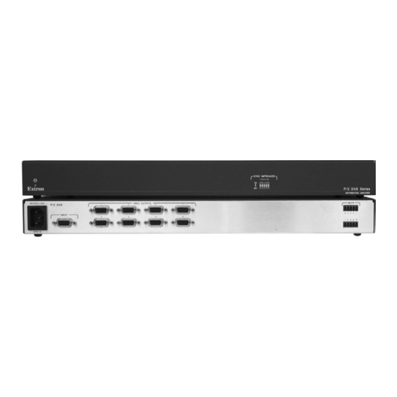
Rear Panel Features All power, input and output connections are located on the rear panels of all models, as shown in the figure below. 100-240V 0.3A INPUT 50/60 Hz 100-240V 0.3A INPUT 50/60 Hz 100-240V 0.3A INPUT 50/60 Hz 100-240V 0.3A INPUT 50/60 Hz... -
Page 18: Operation
Installation and Operation, cont’d Operation After the distribution amplifier and its connected devices are powered up, the system is fully operational. If any problems occur, ensure that the cables are properly routed and connected. Sync impedance switches To solve laptop compatibility issues on the video input, or reflection problems on the video output, use these dip switches to correct for sync impedance mismatches. -
Page 19: Video Input And Output Connections
Video Input and Output Connections All models are able to accept RGBHV, RGBS, RGsB, RsGsBs, YUV (tri-level and bi-level sync), S-video and composite video, and resolutions from VGA (640 x 480) to QXGA (2048 x 1536). The signal is distributed without modification: the output format follows the input format. -
Page 20: Audio Input
Installation and Operation, cont’d Audio input For models P/2 DA8 A and P/2 DA12 A, use a female 3.5 mm mini Tip Ring Sleeve (TRS) connector to provide an unbalanced audio input. Switch off power to the distribution amplifier and audio source. -
Page 21: Mute Control
NO GROUND HERE. Sleeve(s) NO GROUND HERE. Unbalanced Stereo Output CAUTION For unbalanced audio, connect the sleeve(s) to the center contact ground. the sleeve(s) to the negative (-) contacts. Figure 2-8 — Audio output wiring Mute Control The mute control provides a way to mute individual outputs, or all outputs at once. -
Page 22: Troubleshooting
Installation and Operation, cont’d Troubleshooting After input and display devices are connected to the distribution amplifier and all units are powered up, the system is fully operational. If any problems occur, ensure that the cables are properly routed and connected. Some common problems and diagnostic checks are shown below: If the LED light on the front panel is not on, the distribution amplifier is not receiving power. -
Page 23: Appendix A • Reference Information
P/2 DA8 and P/2 DA12 Series A ppendix A Reference Information Specifications Included Parts Accessories... - Page 24 Specifications Video Gain ... Unity Bandwidth ... 350 MHz (-3 dB) Video Input Number/signal type ... 1 VGA-QXGA RGBHV, RGBS, RGsB, Connectors ... (1) 15-pin HD female (optional Mac/VGA Nominal level ... 1.0 Vp-p for Y of component video and Minimum/maximum levels ...
- Page 25 Sync Input type ... RGBHV, RGBS, RGsB, RsGsBs; bi-level Output type ... RGBHV, RGBS, RGsB, RsGsBs; bi-level Input level ... 2.0 V to 5.0 Vp-p (TTL) Output level ... 0.3 Vp-p for component video (bi-level Input impedence ... 10k ohms or 510 ohms (default), selectable Output impedence ...
- Page 26 Reference Information, cont’d Audio — P/2 DA8 A, P/2 DA12 A Gain ... Unbalanced output: 0 dB; Frequency response ... 20 Hz to 20 kHz, ± 0.2 dB THD + Noise ... 0.03% @ 1 kHz at nominal level S/N ... >90 dB at maximum output (unweighted) Stereo channel separation ...
- Page 27 Contact closure pin configurations P/2 DA8 series... A = mute all outputs, 1 = mute output 1, P/2 DA12 series... A = mute all outputs, 1 = mute output 1, General Power ... 100 VAC to 240 VAC, 50/60 Hz, 30 watts, Temperature/humidity ...
-
Page 28: Optional Accessories And Cables
Reference Information, cont’d Included Parts Included Parts P/2 DA8 or P/2 DA8 A or P/2 DA12 or P/2 DA12 A IEC Power Cord Tweeker Rubber Feet (4) 3.5 mm, 3-pole captive screw connector w/tail (blue) — Audio models only (2) 3.5 mm, 4-pole captive screw connector w/tail (blue) —... - Page 29 Accessories SY VGAM-RGBHVF, VGA male to BNC female molded adapter, various lengths SY VGAM-RGBHVF, VGA male to BNC female pig tail adapter, various lengths MHR-5 BNC Series, BNC male to male 5 conductor MHR cables, various lengths MHR-5P BNC Series, BNC male to male 5 conductor plenum MHR cables, various lengths M59-5 BNC Series, BNC male to male 5...
- Page 30 Reference Information, cont’d P/2 DA8 and P/2 DA12 • Reference Information...
- Page 31 Note: This equipment has been tested and found to comply with the limits for a Class A digital device, pursuant to part 15 of the FCC Rules. These limits are designed to provide reasonable protection against harmful interference when the equipment is operated in a commercial environment.
- Page 32 Extron Electronics, USA 1230 South Lewis Street Anaheim, CA 92805 800.633.9876 714.491.1500 FAX 714.491.1517 www.extron.com Extron Electronics, Europe Beeldschermweg 6C 3821 AH Amersfoort, The Netherlands +800.3987.6673 +31.33.453.4040 FAX +31.33.453.4050 © 2008 Extron Electronics. All rights reserved. Extron Electronics, Asia Extron Electronics, Japan 135 Joo Seng Rd.
Need help?
Do you have a question about the VGA Distribution Amplifiers P/2 DA12 Series and is the answer not in the manual?
Questions and answers