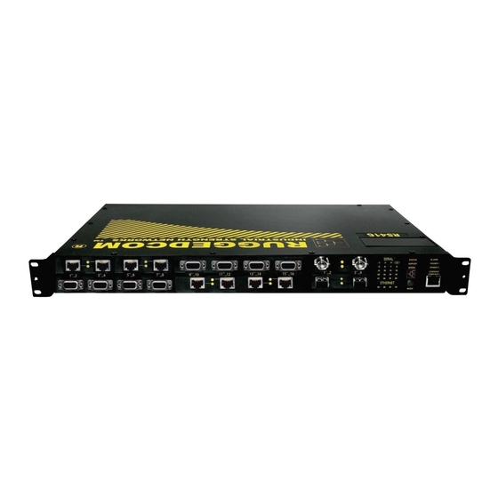
RuggedCom RuggedServer RS416 Installation Manual
Modular serial device server with integrated managed ethernet switch
Hide thumbs
Also See for RuggedServer RS416:
- Installation manual (36 pages) ,
- Specification sheet (12 pages) ,
- Installation manual (43 pages)
Table of Contents
Advertisement
Quick Links
All manuals and user guides at all-guides.com
RuggedServer™ ™ ™ ™ RS
RuggedServer
RuggedServer
RuggedServer
Modular Serial Device Server with Integrated Managed
RuggedCom Inc. I 30 Whitmore Road, Woodbridge, Ontario, Canada L4L 7Z4
Tel: (905) 856-5288 I Fax: (905) 856-1995 I Toll Free: (888) 264-0006
Ethernet Switch
Installation Guide
www.ruggedcom.com
RS416
416
RS
RS
416
416
Advertisement
Table of Contents

Related Manuals for RuggedCom RuggedServer RS416


Summary of Contents for RuggedCom RuggedServer RS416
- Page 1 RuggedServer™ ™ ™ ™ RS RuggedServer RS416 RuggedServer RuggedServer Modular Serial Device Server with Integrated Managed Ethernet Switch Installation Guide www.ruggedcom.com RuggedCom Inc. I 30 Whitmore Road, Woodbridge, Ontario, Canada L4L 7Z4 Tel: (905) 856-5288 I Fax: (905) 856-1995 I Toll Free: (888) 264-0006...
- Page 2 Trademarks: Ethernet is a trademark of Xerox Corporation RuggedSwitch, RuggedRated, ROS and eRSTP are trademarks of RuggedCom® Inc. © 2008 RuggedCom Inc. All rights reserved Rev104...
-
Page 3: Table Of Contents
Failsafe Relay Contact Ratings................. 29 Data Port Specifications..................30 5.3.1 Serial Ports ....................30 5.3.2 Ethernet Ports.................... 31 Type Test Specifications................... 33 Operating Environment..................34 Mechanical Specifications ................34 Agency Approvals ......................... 36 Warranty..........................36 © 2008 RuggedCom Inc. All rights reserved Rev104... -
Page 4: Table Of Figures
Table 8: Failsafe Relay Contact Ratings ..................29 Table 9: Copper Port Specification....................30 Table 10: Fiber Optic Port Specification..................30 Table 11: Ethernet Ports - Copper Specifications ................31 Table 12: Ethernet Ports – Fiber Optic Specifications..............31 © 2008 RuggedCom Inc. All rights reserved Rev104... - Page 5 Table 14: Type Test Specification - Electrical Environment ............33 Table 15: Type Test Specification - Atmospheric Environment............33 Table 16: Operating Environment ....................34 Table 17: Mechanical Specifications....................34 Table 18: Agency Approvals ......................36 © 2008 RuggedCom Inc. All rights reserved Rev104...
-
Page 6: Product Overview
Coupled with the ruggedized hardware design, the RS416 is ideal for creating mission-critical, real-time, control applications in any harsh environment. The RS416 is also backed by RuggedCom's all inclusive five year warranty and unsurpassed technical support. - Page 7 • Port Rate Limiting and Broadcast Storm Limiting • Port configuration, status, statistics, mirroring, security Management Tools • Web-based, Telnet, CLI management interfaces • SNMP v1/v2/v3 • Remote Monitoring (RMON) • Rich set of diagnostics with logging and alarms © 2008 RuggedCom Inc. All rights reserved Rev104...
-
Page 8: Display Panel Description
Power supply operating normal Power 1 / 2 Power supply failure Alarm exist – login to console to determine alarm code Alarm No alarms exist Table 1: LED Display – Device status LED behavior definition © 2008 RuggedCom Inc. All rights reserved Rev104... - Page 9 > 57600 bps Green (Solid) 10 0Mbps 19200 bps – 57600 bps Speed Orange (Solid) 10 Mbps < 19200 bps No link No link Table 2: LED Display - Port LED behavior definition © 2008 RuggedCom Inc. All rights reserved Rev104...
-
Page 10: Installation
See Figure 2 for rack mount orientation examples. Figure 2: RS416 Series Rack mount chassis orientation options – Front and rear mount. © 2008 RuggedCom Inc. All rights reserved Rev104... -
Page 11: Rack Mounting
Although forced airflow is not necessary, any increase in airflow will result in a reduction of ambient temperature that will improve long-term reliability of all equipment mounted within the rack space. © 2008 RuggedCom Inc. All rights reserved Rev104... -
Page 12: Panel And Din Rail Mounting
1” DIN rail using the grooves in the adapter, secured using the included Philips screw. See Figure 5 for a PANEL/DIN mount diagram. Figure 5: RS416 Series PANEL/DIN RAIL mounting diagram with © 2008 RuggedCom Inc. All rights reserved Rev104... -
Page 13: Power Supply Wiring And Grounding
The safety cover must be re-attached after wiring to ensure personnel safety. Refer to Table 3 below for a description of each terminal as well as sections 4.2.1 through 4.2.3 for wiring examples. © 2008 RuggedCom Inc. All rights reserved Rev104... - Page 14 AC. Relay NO Contact Normally open, failsafe relay contact. Relay Common Failsafe relay common contact. Relay NC Contact Normally closed, failsafe relay contact. Table 3: RS416 Power terminal block connection description © 2008 RuggedCom Inc. All rights reserved Rev104...
-
Page 15: Ac Power Supply Wiring Examples
3. When equipped with two HI voltage power supplies, independent AC sources can be used to power the product for greater redundancy. However, separate circuit breakers must be installed and separately identified (not shown in above figure). © 2008 RuggedCom Inc. All rights reserved Rev104... -
Page 16: Dc Power Supply Wiring Examples
5. When equipped with two DC voltage power supplies (88-300VDC rated); independent DC sources may be used to power the product for greater redundancy. However, separate circuit breakers must be installed and separately identified (as shown in the above figure). © 2008 RuggedCom Inc. All rights reserved Rev104... -
Page 17: Dual Power Supplies Wiring Examples
3. A circuit breaker is not required for 12, 24 or 48 VDC rated power supplies. 4. Separate circuit breakers must be installed and separately identified. 5. Equipment must be installed according to the applicable country wiring codes. © 2008 RuggedCom Inc. All rights reserved Rev104... -
Page 18: Dielectric Strength (Hipot) Testing
HIPOT testing. Figure 11 shows the proper HIPOT test connections and should be followed to avoid damage to the device. Figure 11: Dielectric Strength (HIPOT) Testing © 2008 RuggedCom Inc. All rights reserved Rev104... -
Page 19: Failsafe Alarm Relay Wiring
The failsafe relay current and power handling capabilities are defined in Figure 12: Failsafe Alarm Relay Wiring © 2008 RuggedCom Inc. All rights reserved Rev104... -
Page 20: Console Port Wiring
Figure 13: Console port location on display board Figure 14: Console cable For user reference, the console cable pin-out is show in the table below. RuggedCom RS232 over RJ45 pin-out specification Signal Name (PC is DTE) Female DB9 Male RJ45 DCD –... -
Page 21: Serial Ports
RS422, or RS232 devices to communicate over secure, noise immune, optically isolated, fiber optic cabling at extended distances as well as protocol independent conversion to multimode fiber optics. Figure 15: Fiber Serial Interface (ST Connector) © 2008 RuggedCom Inc. All rights reserved Rev104... -
Page 22: Rs232/Rs485/Rs422 Via Db9
5V so that DTE devices that require DCD, DTR, or CTS signals will operate. However, hardware flow control via RTS is not recognized. 3. The Common terminals are optically isolated; however, there is transient voltage protection circuitry between the Common terminals and chassis ground. © 2008 RuggedCom Inc. All rights reserved Rev104... -
Page 23: Rs232/Rs485/Rs422 Via Rj45
5V so that DTE devices that require DCD, DTR, or CTS signals will operate. However, hardware flow control via RTS is not recognized. 3. The Common terminals are optically isolated; however, there is transient voltage protection circuitry between the Common terminals and chassis ground. © 2008 RuggedCom Inc. All rights reserved Rev104... -
Page 24: Rs485 Wiring
5. The shield should be connected to earth ground at a single point to avoid loop currents 6. The twisted pair should be terminated at each end of the chain. The figure below shows the recommended RS485 wiring. Figure 18: Conceptual recommended RS485 wiring diagram © 2008 RuggedCom Inc. All rights reserved Rev104... -
Page 25: Serial Port Transient Protection
All manuals and user guides at all-guides.com 4.6.5 Serial Port Transient Protection RuggedCom does not recommend the use of copper cabling of any length for critical real-time substation automation applications. However, transient suppression circuitry is present on all copper ports to protect against damage from electrical transients and to ensure IEC 61850-3 and IEEE 1613 Class 1 conformance. -
Page 26: Ethernet Ports
No Connection Figure 19: RJ45 port pins configuration. NOTE: RuggedCom does not recommend the use of copper cabling of any length for critical real- time substation automation applications. However, transient suppression circuitry is present on all copper ports to protect against damage from electrical transients and to ensure IEC 61850-3 and IEEE 1613 Class 1 conformance. -
Page 27: Fiber Optic Ports
(i.e. RX and TX will be reversed). Figure 21: 100FX MTRJ connector Figure 22: 100FX ST connector Figure 20: 10FL ST connector Figure 24: 100FX SC connector Figure 23: 100FX LC connector © 2008 RuggedCom Inc. All rights reserved Rev104... -
Page 28: Ethernet Panel Description
LED will be solid for ports with link, and will blink for activity. The diagram in Figure 25 highlights the port and the associated link/activity LED. Figure 25: Ethernet panel LED description © 2008 RuggedCom Inc. All rights reserved Rev104... -
Page 29: Technical Specifications
Parameter Value (Resistive Load) Max Switching Voltage 240VAC, 125VDC Rated Switching Current 2A @ 240VAC 0.15A @ 125VDC, 2A @ 30VDC Max Switching Capacity 150W, 500VA Table 8: Failsafe Relay Contact Ratings © 2008 RuggedCom Inc. All rights reserved Rev104... -
Page 30: Data Port Specifications
Table 10: Fiber Optic Port Specification NOTES: 1. Maximum segment length is greatly dependent on factors such as fiber quality, and number of patches and splices. Please consult RuggedCom sales associates when determining maximum segment distances. © 2008 RuggedCom Inc. All rights reserved... -
Page 31: Ethernet Ports
1310 9/125 -5 / 0 32.5 12-11-0032 SM / LC 12-11-0033 SM / SC 1310 9/125 0 / 5 39.5 12-11-0034 SM / LC Table 12: Ethernet Ports – Fiber Optic Specifications © 2008 RuggedCom Inc. All rights reserved Rev104... - Page 32 NOTES: 1. Maximum segment length is greatly dependent on factors such as fiber quality, and number of patches and splices. Please consult RuggedCom sales associates when determining maximum segment distances. 2. All optical power numbers are listed as dBm averages.
-
Page 33: Type Test Specifications
Test Ad: 16 hrs @ -40°C IEC 60068-2-2 Temperature (Dry Heat) 85°C Test Bd: 16 hrs @ 85°C IEC 60068-2-30 Humidity non-condensing Test Db: 6 cycles, 55°C, 95% Humidity Table 15: Type Test Specification - Atmospheric Environment © 2008 RuggedCom Inc. All rights reserved Rev104... -
Page 34: Operating Environment
(Length x Width x Height) 18.29 x 10.17 x 1.74 inches Dimensions with mounting brackets (464,57) x (258,32) x (44,20) mm installed Weight 10 lb (4.5 Kg) Enclosure 18 AWG galvanized steel Table 17: Mechanical Specifications © 2008 RuggedCom Inc. All rights reserved Rev104... - Page 35 All manuals and user guides at all-guides.com Figure 26: Mechanical Drawing © 2008 RuggedCom Inc. All rights reserved Rev104...
-
Page 36: Agency Approvals
EN60825-1:1994 + A11:1996 + A2:2001 Compliant Table 18: Agency Approvals 7 Warranty RuggedCom warrants this product for a period of five (5) years from date of purchase. For warranty details, visit http://www.ruggedcom.com or contact your customer service representative. Should this product require warranty or service contact the factory at: RuggedCom Inc.
Need help?
Do you have a question about the RuggedServer RS416 and is the answer not in the manual?
Questions and answers