Endress+Hauser Proline 300 Brief Operating Instructions
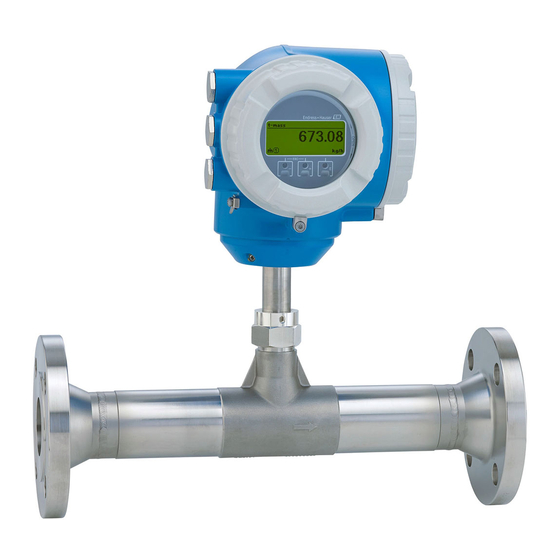
Transmitter with thermal mass flow sensor
Hide thumbs
Also See for Proline 300:
- Brief operating instructions (44 pages) ,
- Brief operating instructions (40 pages) ,
- Brief operating instructions (40 pages)
Table of Contents
Advertisement
Quick Links
KA01445D/06/EN/02.21
71528708
2021-07-01
Products
Brief Operating Instructions
Proline 300
Modbus RS485
Transmitter with thermal mass flow sensor
These instructions are Brief Operating Instructions; they are
not a substitute for the Operating Instructions pertaining to
the device.
Brief Operating Instructions part 2 of 2: Transmitter
Contain information about the transmitter.
Brief Operating Instructions part 1 of 2: Sensor → 3
Solutions
Services
Advertisement
Table of Contents

Related Manuals for Endress+Hauser Proline 300


Summary of Contents for Endress+Hauser Proline 300
- Page 1 Solutions Services KA01445D/06/EN/02.21 71528708 2021-07-01 Brief Operating Instructions Proline 300 Modbus RS485 Transmitter with thermal mass flow sensor These instructions are Brief Operating Instructions; they are not a substitute for the Operating Instructions pertaining to the device. Brief Operating Instructions part 2 of 2: Transmitter Contain information about the transmitter.
- Page 2 Proline 300 Modbus RS485 Order code: XXXXX-XXXXXX Ser. no.: XXXXXXXXXXXX Ext. ord. cd.: XXX.XXXX.XX Serial number www.endress.com/deviceviewer Endress+Hauser Operations App A0023555 Endress+Hauser...
- Page 3 These Brief Operating Instructions are Brief Operating Instructions Part 2: Transmitter. The "Brief Operating Instructions Part 1: Sensor" are available via: • Internet: www.endress.com/deviceviewer • Smart phone/tablet: Endress+Hauser Operations App Detailed information about the device can be found in the Operating Instructions and the other documentation: • Internet: www.endress.com/deviceviewer •...
-
Page 4: Table Of Contents
Table of contents Proline 300 Modbus RS485 Table of contents About this document ............. . 5 Symbols used . -
Page 5: About This Document
Proline 300 Modbus RS485 About this document About this document Symbols used 1.1.1 Safety symbols DANGER This symbol alerts you to a dangerous situation. Failure to avoid this situation will result in serious or fatal injury. WARNING This symbol alerts you to a dangerous situation. Failure to avoid this situation can result in serious or fatal injury. - Page 6 About this document Proline 300 Modbus RS485 Symbol Meaning Protective Earth (PE) A terminal which must be connected to ground prior to establishing any other connections. The ground terminals are situated inside and outside the device: • Inner ground terminal: Connects the protectiv earth to the mains supply.
-
Page 7: Safety Instructions
Proline 300 Modbus RS485 Safety instructions Safety instructions Requirements for the personnel The personnel must fulfill the following requirements for its tasks: ‣ Trained, qualified specialists must have a relevant qualification for this specific function and task. ‣ Are authorized by the plant owner/operator. -
Page 8: Occupational Safety
Verification for borderline cases: ‣ For special fluids and fluids for cleaning, Endress+Hauser is glad to provide assistance in verifying the corrosion resistance of fluid-wetted materials, but does not accept any warranty or liability as minute changes in the temperature, concentration or level of contamination in the process can alter the corrosion resistance properties. -
Page 9: Product Safety
RJ45)! Order code for "Approval", options (Ex de): BB, C2, GB, MB, NB Product description The device consists of a Proline 300 transmitter and a Proline t-mass thermal mass flowmeter sensor. The device is available as a compact version: The transmitter and sensor form a mechanical unit. - Page 10 Product description Proline 300 Modbus RS485 N ic te r e r g ö ff iz e te n r ir s io I/ O – A0029586 Connection compartment cover Display module Transmitter housing Electronics compartment cover Sensor Use of the device with the remote display and operating module DKX001 → 21.
-
Page 11: Installation
Proline 300 Modbus RS485 Installation Installation For detailed information about mounting the sensor, see the Sensor Brief Operating Instructions → 3 Turning the transmitter housing To provide easier access to the connection compartment or display module, the transmitter housing can be turned. - Page 12 Installation Proline 300 Modbus RS485 4 mm 7 Nm (5.2 lbf ) A0043150 2 Ex housing Release the fixing screws. Turn the housing to the desired position. Tighten the securing screws. Endress+Hauser...
-
Page 13: Turning The Display Module
Proline 300 Modbus RS485 Installation Turning the display module The display module can be turned to optimize display readability and operability. – – – 3 mm A0030035 Depending on the device version: Loosen the securing clamp of the connection compartment cover. -
Page 14: Electrical Connection
Electrical connection Proline 300 Modbus RS485 Electrical connection NOTICE The measuring device does not have an internal circuit breaker. ‣ For this reason, assign the measuring device a switch or power-circuit breaker so that the power supply line can be easily disconnected from the mains. - Page 15 Proline 300 Modbus RS485 Electrical connection Signal cable Modbus RS485 The EIA/TIA-485 standard specifies two types of cable (A and B) for the bus line which can be used for every transmission rate. Cable type A is recommended. For detailed information about the specification of the connecting cable, see the Operating Instructions for the device.
- Page 16 Electrical connection Proline 300 Modbus RS485 Standard cable - customer-specific cable No cable is supplied, and it must be provided by the customer (up to max. 300 m (1 000 ft)) for the following order option: Order code for DKX001: Order code 040 for "Cable", option 1 "None, provided by customer, max 300 m"...
-
Page 17: Connecting The Measuring Device
Proline 300 Modbus RS485 Electrical connection 5.2.3 Terminal assignment Transmitter: supply voltage, input/outputs The terminal assignment of the inputs and outputs depends on the individual order version of the device. The device-specific terminal assignment is documented on an adhesive label in the terminal cover. - Page 18 Electrical connection Proline 300 Modbus RS485 5.3.1 Connecting the transmitter A0026781 Terminal connection for supply voltage Terminal connection for signal transmission, input/output Terminal connection for signal transmission, input/output or terminal connection for network connection via service interface (CDI-RJ45); optional: connection for external WLAN antenna or...
- Page 19 Proline 300 Modbus RS485 Electrical connection N ic N ic t e r t e r e r g ö f f e r g ö f f iz e iz e t e n t e n r ir...
- Page 20 Electrical connection Proline 300 Modbus RS485 22 mm 24 mm – A0029816 10. Connect the cable in accordance with the terminal assignment . Signal cable terminal assignment: The device-specific terminal assignment is documented on an adhesive label in the terminal cover.
-
Page 21: Ensuring Potential Equalization
Proline 300 Modbus RS485 Electrical connection 5.3.2 Connecting the remote display and operating module DKX001 The remote display and operating module DKX001 is available as an optional extra. • The measuring device is always supplied with a dummy cover when the remote display and operating module DKX001 is ordered directly with the measuring device. - Page 22 Electrical connection Proline 300 Modbus RS485 Hardware addressing A0029634 Set the desired device address using the DIP switches in the connection compartment. A0029633 To switch addressing from software addressing to hardware addressing: set the DIP switch to On. The change of device address takes effect after 10 seconds.
-
Page 23: Ensuring The Degree Of Protection
Proline 300 Modbus RS485 Electrical connection ‣ A0029632 Switch DIP switch No. 3 to On. Ensuring the degree of protection The measuring device fulfills all the requirements for degree of protection IP66/67, Type 4X enclosure. To guarantee degree of protection IP66/67, Type 4X enclosure, carry out the following steps after the electrical connection: Check that the housing seals are clean and fitted correctly. - Page 24 Electrical connection Proline 300 Modbus RS485 Are all the cable glands installed, firmly tightened and leak-tight? Cable run with "water trap" → 23? If supply voltage is present, do values appear on the display module? Endress+Hauser...
-
Page 25: Operation Options
Proline 300 Modbus RS485 Operation options Operation options Overview of operation options A0030213 Local operation via display module Computer with Web browser (e.g. Internet Explorer) or with operating tool (e.g. FieldCare, DeviceCare, AMS Device Manager, SIMATIC PDM) Mobile handheld terminal with SmartBlue App Control system (e.g. -
Page 26: Structure And Function Of The Operating Menu
Operation options Proline 300 Modbus RS485 Structure and function of the operating menu 6.2.1 Structure of the operating menu Operating menu for operators and maintenances Language Operation task-oriented Setup Diagnostics Operating menu for experts Expert function-oriented A0014058-EN 3 Schematic structure of the operating menu 6.2.2... -
Page 27: Access To The Operating Menu Via The Local Display
Proline 300 Modbus RS485 Operation options Access to the operating menu via the local display X X X X X X 19.184 mA 12.5 X X X X X X Language à English 20.50 Deutsch Español Français Xxxxxxx A B C D E F G H I J K M N O P Q R S T U V W +0.000 Xx... - Page 28 Operation options Proline 300 Modbus RS485 6.3.1 Operational display Explanatory symbols for the measured value Status area • Depends on the device version, e.g.: The following symbols appear in the status area of the • : Volume flow operational display at the top right: •...
- Page 29 Proline 300 Modbus RS485 Operation options Numeric editor Confirms selection. Moves the input position one position to the left. Exits the input without applying the changes. Inserts decimal separator at the input position. Inserts minus sign at the input position.
-
Page 30: Access To The Operating Menu Via The Operating Tool
System integration Proline 300 Modbus RS485 Keys and meaning Minus/Enter key combination (press the keys simultaneously) With an operational display: • If keypad lock is active: Pressing the key for 3 s deactivates the keypad lock. • If keypad lock is not active: Pressing the key for 3 s opens the context menu including the option for activating the keypad lock. -
Page 31: Commissioning
Proline 300 Modbus RS485 Commissioning Commissioning Function check Before commissioning the measuring device: ‣ Make sure that the post-installation and post-connection checks have been performed. • "Post-installation check" checklist → 13 • "Post-connection check" checklist → 23 Setting the operating language... -
Page 32: Configuring The Measuring Device
Commissioning Proline 300 Modbus RS485 Configuring the measuring device The Setup menu with its submenus and various guided wizards is used for fast commissioning of the device. They contain all the parameters required for configuration, such as for measurement or communication. -
Page 33: Diagnostic Information
Proline 300 Modbus RS485 Diagnostic information Diagnostic information Faults detected by the self-monitoring system of the measuring device are displayed as a diagnostic message in alternation with the operational display. The message about remedial measures can be called up from the diagnostic message, and contains important information on the fault. - Page 36 *71528708* 71528708 www.addresses.endress.com...
Need help?
Do you have a question about the Proline 300 and is the answer not in the manual?
Questions and answers