
Related Manuals for Hisense AVY-07UXJSJA


Summary of Contents for Hisense AVY-07UXJSJA
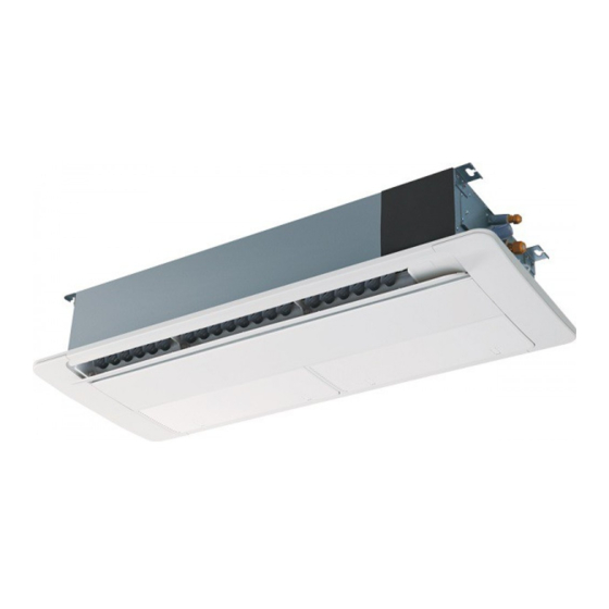
- Page 1 AVY-14UXJSJA AVY-07UXJSJA 1-Way AVY-18UXJSKA Cassette AVY-09UXJSJA Type AVY-12UXJSJA AVY-24UXJSKA P01135Q ORIGINAL INSTRUCTIONS...
- Page 3 Manufacturing number and manufacturing year: refer to model Nameplate. Notes: This declaration becomes invalid, if technical or operational modifications are introduced without the manufacturers consent. Hisense Italia S.r.l. is authorised to Compile the Technical Construction File. Ad. : Via Montefeltro 6A, 20156 Milano. Name, Surname Position/ Title...
- Page 4 Hisense Hisense Hisense...
-
Page 5: Important Notice
To return your used device, please use the return and collection systems or contact the retailer where the product was purchased. They can take this product for environmental safe recycling. Hisense's Hisense's... - Page 6 Section2 Installation & Maintenance Manual...
- Page 8 The appliance is not to be used by children or person with reduced physical, sensory or mental capabilities,or lack of experience and knowledge, unless they have been given supervision or instruction concerning use of the appliance by a person responsible for their safety. Children should be supervised that they do not play with the appliance.
- Page 9 。,t 。 3. Rem ntrol Switch ACIUTION from the ai tempe ture of the sensor due to 「 阳 。 the difference of the sensing location. 。 。 Press switches nly with fingers. D 。 uching Type Switches press switches by any ther item, as it may This control switch is of touching type.
- Page 10 Regarding the instructions of Wired Remote Control Switch or Wireless Remote Control Switch,read the operation manual attached to the control switch.
- Page 11 outlet Outlet Left Side Knob Right Side Note: There are two grilles on the panel of HP-E-NA, which should be removed respectively.
- Page 12 Left Side Knobs (two) Zoom-in View of Knob Right side Remove the other filter screen in the same way.
- Page 13 Wrench R410A * To avoid damage to the resin covers,before lifting or moving the indoor unit,put a cloth on the resin covers.
- Page 14 Air Panel(optional) Indoor Unit Panel Selected 07~14 HP-D-NA 18~24 HP-E-NA Screw Magnet Ring For Fixing Magnet Ring...
-
Page 15: Service Space
Service Hole(450Min.) 150mm Min. 150mm Min. 500mm Min. 1500mm Min. Piping Connection Distance From Wall Side 1,500mm Min. 150mm Min. Piping Connection Side 500mm Min. 150mm Min. 1,000mm Min. Service Space 230mm Min. - Page 16 Indoor Unit Panel Dimension of Opening A Unit: mm Sizes Model (3) Use a gradienter or transparent plastic hose AVY-07UXJSJA filled with water to level the two directions of AVY-09UXJSJA 1000 1100 indoor unit, length and width sides. AVY-12UXJSJA AVY-14UXJSJA...
- Page 17 Pattern Board for Installation Checking Scale 02 Checking Scale 01 4.3.3 (2) Adjust the distance between indoor unit and ceiling. Adjust the indoor unit to a proper position with the checking scale provided by the factory Bottom View (mm) Ceiling Air Outlet Indoor Unit Refrigerant...
- Page 18 Pipe Diameter (a) Flaring Diameter 12.7mm Drain Pipe Connection Liquid Pipe Connection Gas Pipe Connection (PVC, VP25) Flaring Dimension Perform the flaring work as shown below.
- Page 19 Drain Hose Horizontal or Upward Slope Drain pipe must be installed horizontally or in upward slope to prevent occurrence of air column, or otherwise water will flow from rear of the equipment to cause leakage or abnormal noise when the equipment is shut down. (a) Use the drain pipe and hose clamp provided by the manufacture.
- Page 20 ● Turn OFF the main power switch to the indoor unit and the outdoor unit and wait for at least 3 minutes before electrical wiring work or a periodical check is performed. ● Check to ensure that the indoor fan and the outdoor fan have stopped before electrical wiring work or a periodical check is performed.
- Page 21 (a) Remove electrical box cover (by loosening one screw (A)). Screw A Screw B Loosen two screws (B) on electrical box Screw B component and pull out the component. Fix the wire harness from connecting port to electrical box with cord clamp to prevent it from scratched by edge of container of other component.
- Page 22 Maximum Current EN60 335-1 EN60 335-1 07~09 0.3A 0.4A 12 14 0.75mm 0.5A 0.8A The wire sizes marked with *1 in the above table are selected at the maximum current of the unit according to the European Standard, EN60335-1.Use the wires which are not lighter than the ordinary polyvinyl chloride sheathed flexible cord (code designation H05VV-F).
- Page 23 Capacity ×10 Btu/h DSW4(Unit Mode Code Setting) Capacity ×10 Btu/h DSW3(Capacity Code Setting) DSW6(Unit No. Setting) RSW1(Unit No. Setting) DSW7(Fuse Recover) RSW2(Refrigerant Cycle No. Setting) DSW5(Refrigerant Cycle No. Setting) H-LINK II. H-LINK II. H-LINK II. H-LINK II. of the indoor unit.
- Page 24 1084931 Qingdao Hisense Hitachi Air-conditioning Systems Co., Ltd. Add: 218, Qianwangang Road, Economic & Technical Development Zone, Qingdao, P.R. China http://www.hisense-vrf.com E-mail: export@hisensehitachi.com P01135Q 2018.03...
Need help?
Do you have a question about the AVY-07UXJSJA and is the answer not in the manual?
Questions and answers