Advertisement
Operation, Installation & Maintenance Manual
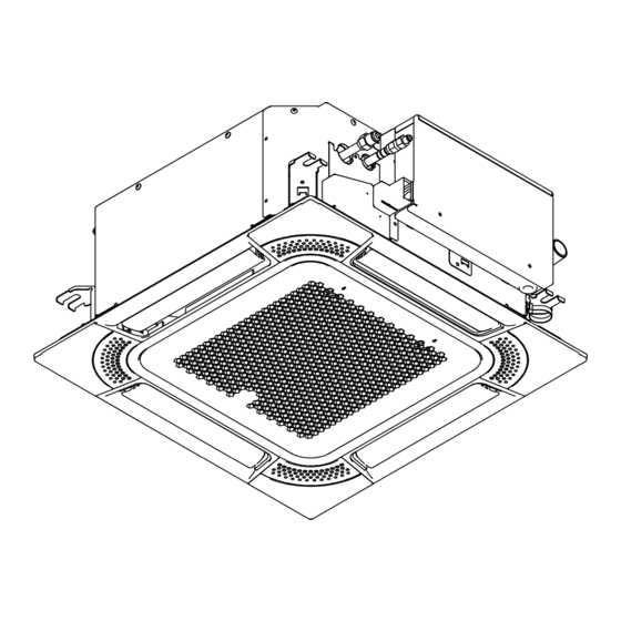
MINI 4-WAY CASSETTE TYPE
THANK YOU FOR PURCHASING
HISENSE CENTRAL AIR
CONDITIONER. PLEASE READ AND
UNDERSTAND THIS MANUAL
BEFORE USING THE AIR
CONDITIONER. KEEP THIS MANUAL
FOR FUTURE REFERNECE.
AVC-05H3FAA
AVC-07H3FAA
AVC-09H3FAA
AVC-12H3FAA
AVC-15H3FAA
AVC-17H3FAA
AVC-19H3FAA
M00388Q
ORIGINAL INSTRUCTIONS
Advertisement
Table of Contents

Related Manuals for Hisense AVC-05H3FAA


Summary of Contents for Hisense AVC-05H3FAA
- Page 1 Operation, Installation & Maintenance Manual MINI 4-WAY CASSETTE TYPE AVC-05H3FAA AVC-07H3FAA AVC-09H3FAA AVC-12H3FAA AVC-15H3FAA AVC-17H3FAA AVC-19H3FAA THANK YOU FOR PURCHASING HISENSE CENTRAL AIR CONDITIONER. PLEASE READ AND M00388Q UNDERSTAND THIS MANUAL BEFORE USING THE AIR ORIGINAL INSTRUCTIONS CONDITIONER. KEEP THIS MANUAL FOR FUTURE REFERNECE.
-
Page 3: Important Notice
This manual describes and introduces this heat pump air conditioner in a unified manner, so it's applicable for your and other air conditioners. Hisense pursues a policy of continuous improvement in design and performance of products. The right is therefore reserved to change specifications without notice. - Page 4 DANGER Please don't perform installation works such as refrigerant piping connection, drain pipe connection, and wiring connection. Violations may result in system leakage, electrical failure or fire. In the case of fire, please turn off the power immediately; please don't touch electrical parts with the hands, or electric shock may arise. Do not pour water into the indoor or outdoor unit.
-
Page 5: Correct Disposal Of This Product
Correct Disposal of this product This marking indicates that this product should not be disposed with other household wastes. To prevent possible harm to the environment or human health from uncontrolled waste disposal, recycle it responsibly to promote the sustainable reuse of material resources. To return your used device, please use the return and collection systems or contact the retailer where the product was purchased. - Page 7 1.Safety Precautions Tools & Instruments for Installation Transportation & Handling 3.1 Transportation 3.2 Handling of Indoor Unit Installation of Indoor Unit 4.1 Factory-Supplied Accessories 4.2 Initial Check 4.3 Installation Refrigerant Piping Work 5.1 Piping Materials 5.2 Piping Connection 6.Drain Pipe Electrical Wiring 7.1 General Check 7.2 Wiring...
- Page 9 Do not install the indoor unit, outdoor unit, Do not perform installation work, refrigerant piping remote control switch and cable work, drain piping and electrical wiring connection within approximately 9.8ft.(3m) from strong without referring to the installation manual. electromagnetic wave radiators such as Check that the ground wire is securely connected.
-
Page 10: Installation
Do not install the indoor unit in a machinery 4.2 Initial Check shop or kitchen where vapor from oil or its mist flows to the indoor unit. Install the indoor unit in a space for easy operation Once the oil deposits on the heat exchanger, it and maintenance as shown in Fig. - Page 11 4.3.3 Mounting the Indoor Unit For Steel Beam For Concrete Slab Mount the indoor unit as shown in Fig. 4.4. 5-29/32~6-19/64in.(150~160mm) Screw in Mount field-supplied parts 220~331lbs(100~150kg) Suspension bolt 4-M10 or W3/8 Concrete 8-M10 or W3/8 Suspension Bolt Washer 8-M10 or W3/8 Fixing Point Beam (1) Mount nuts and washers to the suspension bolts.
- Page 12 4.3.4 Adjust the Distance between Indoor Unit (b) For ceiling without panel and Ceiling Pattern Board for Installation Please cover the machine with plastic cloth to keep it clean during installation. Check the level of water pan using a water level to avoid incorrect installation of drain discharge mechanism.
-
Page 13: Piping Connection
(2) As shown in Fig. 5.4, two spanners shall be used for 5.2 Piping Connection tightening the nut (1) The connection point and diameter of piping are shown in Figs. 5.1 and 5.2. Unit: in.(mm) 5-43/64(144) Liquid Pipe 3-21/32(93)Gas Pipe Pipe Size in.(mm) Tightening Torque ft·lbs (N·m) 1/4(Φ6.35) 14.8(20) - Page 14 (1) The position of the drain pipe connection is shown in Fig. 6.1. Where the relative humidity of air inlet or (2) Prepare a polyvinyl chloride pipe with a ambient air exceeds 80%, an auxiliary water pan 32mm outer diameter. shall be fabricated at installation site and placed (3) Fasten the tubing to the drain hose with the under the indoor unit, as shown in Fig.
- Page 15 Electrical 7.2 Wiring The electrical wiring connection for indoor unit is shown in Fig. 7.1. Turn OFF the main power switches to the indoor (1) Connect transmission wiring to the PBC unit and outdoor unit before electrical wiring or in electrical box through the connection hole periodical check, and wait for at least three on electrical box.
- Page 16 Clamp for Clamp for Transmission Wiring Clamp Power Wiring Power Wiring Transmission Wiring Main PCB <Power Wiring> <Transmission Wiring> Clamp for Transmission Wiring Cord Clamp 208/230V 60Hz Fig. 7.1 Electrical Wiring Connection for Indoor Unit 7.3 Field Wire Size for Power Source Line Units Power supply Fan motor...
- Page 17 Test run should be performed according to the Installation & Maintenance Manual. Do no operate the system until all the check points Pay attention to the following items while the system are cleared. is running. (A) Do not touch any of the parts by hand at the (A) Check to ensure the electrical resistance between discharge gas side, since the temperatures of terminal and ground is more than 1 MΩ.
-
Page 18: Setting Of Dip Switches
10.1 Setting of DIP Switches (c) Safety reset (DSW7) Factory settings (1) DIP switch must be set with power sources of the indoor and outdoor units in OFF state. Otherwise, the settings are invalid. Once strong current is (2) The DIP switches are located as shown in the accidentally connected to figure below. - Page 20 1 pc Drain Pipe: 1 pc Filler Piece: 4 pcs Filler Piece of heat insulation: 4 pcs Pipe Clamp: 1 pc 1123292 Add: 218, Qianwangang Road, Economic & Technical Development Zone, Qingdao, P. R. China http: //www.hisense-vrf.com E-mail: export@hisensehitachi.com M00388Q 2020.02...
Need help?
Do you have a question about the AVC-05H3FAA and is the answer not in the manual?
Questions and answers