Table of Contents
Advertisement
TECHNICAL & SERVICE MANUAL
MODEL:
Duct
ADT-09UX4SRNL3
ADT-12UX4SSNL3
ADT-18UX4SFKL3
AUD-09UX4SRNL3
AUD-12UX4SSNL3
AUD-18UX4SFKL3
AUD-24UX4SFLL3
AUD-36UX4SAHH3
AUD-42UX6STHH3
AUD-48UX6SPHH3
AUD-60UX6SPHH3
Ceiling & Floor
AVT-18UR4SFA3
AUV-18UR4SFA3
AUV-24UR4SFA3
AUV-36UR4SAB3
AUV-42UR6STC3
AUV-48UR6SPC3
AUV-60UR6SPC3
—DC-INVERTER AIR CONDITIONERS
Cassette
ACT-12UR4SSAA3
ACT-18UR4SFAA3
AUC-12UR4SSAA3
AUC-18UR4SFAA3
AUC-24UR4SFGB3
AUC-36UR4SAGB3
AUC-42UR6STHB3
AUC-48UR6SPHB3
AUC-60UR6SPHB3
V1.4
Advertisement
Table of Contents

Related Manuals for Hisense ADT-12UX4SSNL3


Summary of Contents for Hisense ADT-12UX4SSNL3
- Page 1 TECHNICAL & SERVICE MANUAL V1.4 —DC-INVERTER AIR CONDITIONERS MODEL: Duct Cassette ADT-09UX4SRNL3 ACT-12UR4SSAA3 ADT-12UX4SSNL3 ACT-18UR4SFAA3 ADT-18UX4SFKL3 AUC-12UR4SSAA3 AUD-09UX4SRNL3 AUC-18UR4SFAA3 AUD-12UX4SSNL3 AUC-24UR4SFGB3 AUD-18UX4SFKL3 AUC-36UR4SAGB3 AUD-24UX4SFLL3 AUC-42UR6STHB3 AUD-36UX4SAHH3 AUC-48UR6SPHB3 AUD-42UX6STHH3 AUC-60UR6SPHB3 AUD-48UX6SPHH3 AUD-60UX6SPHH3 Ceiling & Floor AVT-18UR4SFA3 AUV-18UR4SFA3 AUV-24UR4SFA3 AUV-36UR4SAB3 AUV-42UR6STC3 AUV-48UR6SPC3...
-
Page 2: Table Of Contents
DC-Inverter Air Conditioner Technical & Service Manual Table of Contents 1. General ..........................1 1.1 Features ......................... 1 1.2 Product lineup ......................4 1.3 Model identification ....................5 1.4 Unit construction ..................... 5 1.5 Working range ......................6 1.6 Product picture ....................... 7 2. -
Page 3: General
1. General 1.1 Features Duct Type Air Conditioner Features Save Installation Space The indoor unit can be installed inside the ceiling conveniently. Optional Static Pressure Optional ESP, a variety of optional installation methods. High Efficiency and Environment Friendly New Refrigerant-R410A ... - Page 4 Cassette Type Air Conditioner Features Save Installation Space The indoor unit can be installed inside the ceiling conveniently. High Efficiency and Environment Friendly New Refrigerant-R410A R410A can protect the environment and do not harm to the ozone layer. 24-hour Timer ON and OFF ...
- Page 5 Ceiling &Floor Air Conditioner Features Save Installation Space The indoor unit’s thickness is only 230mm,can be installed inside the ceiling conveniently. Flexible Installation Options According to the actual installation space,The indoor unit can be installed in the ceiling or on the floor.
-
Page 6: Product Lineup
1.2 Product lineup Model Cooling Type Capacity (×1000Btu/h) Duct ● ● ● ● ● ● ● ● AUD- Type Cassette ● ● ● ● ● ● ● AUC- Type Ceiling& ● ● ● ● ● ● AUV- Floor type ●--- available model DC- INVERTER AIR CONDITIONER TECHNICAL&SERVICE MANUAL... -
Page 7: Model Identification
1.3 Model identification A U D -09 U X 4 S R N L 3 3:Series Number L:Low ESP H:High ESP N:Indoor Unit Code R:Outdoor Unit Code S:Refrigerant R410A F:Refrigerant R22 2:220-230V ~,60Hz, 4:220-240V ~, 50Hz 6:380-415V ~,50Hz X: Wire Romote Controller R:Wireless Romote Controller U:DC-Invert Heat Pump Type , H:Heat Pump Type C:Cooling Only Type ³... -
Page 8: Working Range
1.5 Working range Power Supply Working Voltage 176V ~ 264V(9K~36K),342V ~ 438V(42K~60K) Within a 3% deviation from each voltage at the main terminal of Voltage Imbalance outdoor unit Starting Voltage Higher than 85% of the Rated Voltage Operating temperature range This heat pump air conditioner has been designed for the following outdoor operating temperatures. -
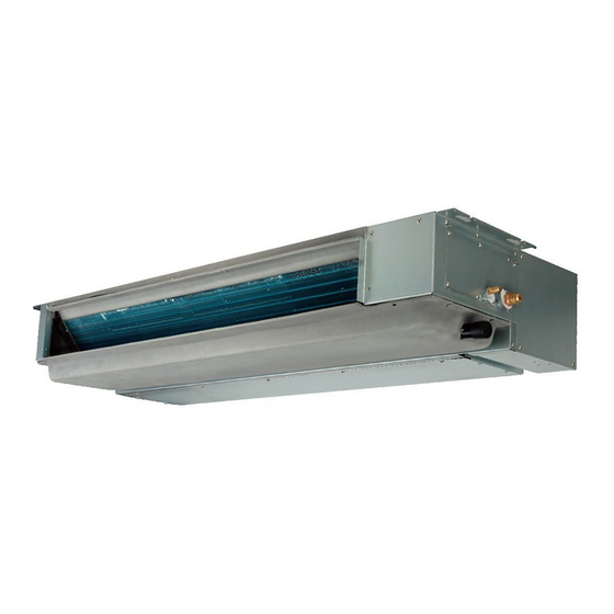
Page 9: Product Picture
1.6 Product picture Duct Type Model ( Cooling capacity ) Indoor Unit Outdoor Unit Model ( Cooling capacity ) Indoor Unit Outdoor Unit DC- INVERTER AIR CONDITIONER TECHNICAL&SERVICE MANUAL... - Page 10 Model (capacity) Indoor Unit Outdoor Unit Model 48K/60K (capacity) Indoor Unit Outdoor Unit DC-� INVERTER AIR CONDITIONER TECHNICAL&SERVICE MANUAL...
- Page 11 Cassette Type Model (capacity) Indoor Unit Outdoor Unit Model (capacity) Indoor Unit Outdoor Unit DC-� INVERTER AIR CONDITIONER TECHNICAL&SERVICE MANUAL...
- Page 12 Model 48K/60K (capacity) Indoor Unit Outdoor Unit DC-� INVERTER AIR CONDITIONER TECHNICAL&SERVICE MANUAL...
- Page 13 Ceiling &Floor Type Model 18K/24K 36K/42K (capacity) Indoor Unit Outdoor Unit Model 48K/60K (capacity) Indoor Unit Outdoor Unit DC-� INVERTER AIR CONDITIONER TECHNICAL&SERVICE MANUAL...
- Page 14 Display panel Cassette Type Ceiling & Floor type DC-� INVERTER AIR CONDITIONER TECHNICAL&SERVICE MANUAL...
- Page 15 Description 1 Run indicator (Red) It lights on during operation. It lights off during SLEEP mode. 2 Emergency switch The filter clean indicator will be off when the switch is pressed. The unit will stop operation if pressing the button.When the unit is off,it will start auto operation if pressing the button,if pressing for more than 5s, the unit will operate in cooling mode.
-
Page 16: Specifications
2. Specifications 2.1 Duct type MODEL Power supply (Indoor) V-ph-Hz 220~240-1-50 220~240-1-50 220~240-1-50 220~240-1-50 220~240-1-50 220~240-1-50 220~240-1-50 220~240-1-50 Power supply (Outdoor) V-ph-Hz 220~240-1-50 220~240-1-50 220~240-1-50 220~240-1-50 220~240-1-50 380~415-3-50 380~415-3-50 380~415-3-50 Max. input consumption 1140 1800 2460 4100 5100 6400 7000 7800 Max. - Page 17 MODEL Indoor fan motor Speed(Hi/Med/Lo) r/min 770/640/540 880/740/610 1130/950/850 890/790/690 800/700/600 910/810/710 1100/1000/900 1100/1000/900 Number of rows Tube pitch(a)xrow 21x13.6 21x13.6 21x13.6 21x13.6 21x18.19 21x18.19 21x18.19 21x18.19 pitch(b) Fin spacing Hydrophilic Hydrophilic Hydrophilic Hydrophilic Hydrophilic Hydrophilic Hydrophilic Hydrophilic Fin type Indoor coil aluminium aluminium...
- Page 18 MODEL Model ASD088SKNA8JT ASN108D43UFZA ATM150D23UFZ ATF235D43UMT ATF310D43UMT ATF310D43UMT ATH356SDPC9FL LNB42FSAMC Type ROTARY ROTARY ROTARY ROTARY ROTARY ROTARY ROTARY ROTARY Brand Highly GMCC GMCC GMCC GMCC GMCC Highly MITSUBISHI Capacity Btu/h 8549 11123 15427 24361 32380 32380 34470 47699 Compressor Input 1165 1940 2600...
- Page 19 MODEL Net/Gross weight 31/34 34/38.5 45/49 51/57 70/80 85/95 113/125 117/129 Type R410a R410a R410a R410a R410 R410 R410A R410A Refrigerant type/Quantity Charged volume 0.83 1.05 1.30 1.70 2.80 3.20 3.78 3.95 Design pressure 4.15/1.60 4.15/1.60 4.15/1.60 4.15/1.60 4.15/1.60 4.15/1.60 4.15/1.60 4.15/1.60 Liquid side/...
-
Page 20: Cassette Type
2.2 Cassette type MODEL Power supply (Indoor) V-ph-Hz 220~240-1-50 220~240-1-50 220~240-1-50 220~240-1-50 220~240-1-50 220~240-1-50 220~240-1-50 Power supply (Outdoor) V-ph-Hz 220~240-1-50 220~240-1-50 220~240-1-50 220~240-1-50 380~415-3-50 380~415-3-50 380~415-3-50 Max. input consumption 1800 2710 4100 5150 6400 6300 7800 Max. input current 12.3 18.1 22.5 11.6... - Page 21 MODEL Fin spacing Hydrophilic Hydrophilic Hydrophilic Hydrophilic Hydrophilic Hydrophilic Hydrophilic Fin type aluminium aluminium aluminium aluminium aluminium aluminium aluminium Indoor coil Ф7, innergroove Ф7, innergroove Ф7.0, innergroove Ф7.0, innergroove Tube outside dia.and type Ф7,innergroove tube Ф7,innergroove tube Ф7,innergroove tube tube tube tube tube...
- Page 22 MODEL Brand GMCC GMCC GMCC GMCC GMCC Highly MITSUBISHI Capacity Btu/h 11123 15427 24361 32380 32380 34470 47699 Compressor Input 1165 1940 2600 2600 3155 4270 Rated current(RLA) 13.2 ESTER OIL ESTEL OIL α 68HES-H or Refrigerant oil POE(VG74)/670 PQE(VG74)/1000 PQE(VG74)/1000 FV50S or PVE/1400 VG74/370...
- Page 23 MODEL Φ6.35/Φ9.52 Φ6.35/Φ12.7 Φ9.52/Φ15.88 Φ9.52/Φ19.05 Φ9.52/Φ19.05 Φ9.52/Φ19.05 Φ9.52/Φ19.05 Liquid side/ Gas side mm(inch) (1/4'/3/ 8') (1/4'/1/ 2') (3/8'/5 /8') (3/8'/3 /4') (3/8'/3 /4') (3/8'/3 /4') (3/8'/3 /4') Refrigerant piping Max. pipe length Max. difference in level Annual energy consumption kWh/a (cooling) Annual energy consumption...
-
Page 24: Ceiling&Floor Type
2.3 Ceiling&Floor type Model 220~240-1-50 220~240-1-50 220~240-1-50 220~240-1-50 220~240-1-50 220~240-1-50 Power supply (Indoor) V-ph-Hz 220~240-1-50 220~240-1-50 220~240-1-50 380~415-3-50 380~415-3-50 380~415-3-50 Power supply (Outdoor) V-ph-Hz Max. input consumption 2600 4100 5100 6400 6300 8200 Max. input current 18.1 22.5 11.6 11.0 13.5 Pdesignc 5.28... - Page 25 Model Hydrophilic Hydrophilic Hydrophilic Hydrophilic Hydrophilic Hydrophilic Fin type aluminium aluminium aluminium aluminium aluminium aluminium Ф7.0, innergroove Ф7.0, innergroove Indoor coil Ф7,innergroove tube Ф7,innergroove tube Ф7, innergroove tube Ф7, innergroove tube Tube outside dia.and type tube tube 691x336x27.2 660x336x40.8 930x336x40.8 1200x336x40.8 1200x336x40.8 1200x336x54.4...
- Page 26 Model YDK65-6-9061& YDK65-6-9061& Model SIC-61FW-F161-1 SIC-61FW-F161-1 SIC-71FW-F8121-1 SIC-81FW-F1138-1 YDK65-6-9024 YDK65-6-9024 Old Model Outdoor fan motor Input Capacitor μF Speed r/min Number of rows Tube pitch(a)x row pitch(b) 21x21.65 21x18.19 21x21.65 21x21.65 21x21.65 21x21.65 Fin spacing Hydrophilic Hydrophilic Hydrophilic Hydrophilic Hydrophilic Hydrophilic Fin type Outdoor coil...
- Page 27 Model Annual energy consumption(heating kWh/a 1564 2059 3064 3491 4252 5232 average) Cooling -15- 48 -15- 48 -15- 48 -15- 48 -15- 48 -15- 48 ℃ Ambient temperature Heating -15 - 24 -15 - 24 -15 - 24 -15 - 24 -15 - 24 -15 - 24 ℃...
-
Page 28: Outlines And Dimensions
3. Outlines and dimensions 3.1 Indoor units Duct type Unit:mm Air outlet 50 90 Air inlet Electric box Gas pipe 44 74 Drain pipe Air outlet Liquid pipe i*200=j Air inlet Model 1170 971 1207 78 250 1246 1039 9K / 12K 73 240 900 701 DC-�... - Page 29 Unit:mm Air inlet ( p*300= ) q Air outlet Liquid pipe Gas pipe Drain pipe Electric box Air inlet ( p*300=)q Air outlet Model 102 117 36K/42K/ 1334 1300 1205 1235 90 140 48K/60K DC-� INVERTER AIR CONDITIONER TECHNICAL&SERVICE MANUAL...
- Page 30 Cassette Type 12K,18K Unit:mm PANEL Air outlet Air outlet Air inlet Display panel Gas pipe Liquid pipe Drain pipe Electric box 575~590(Dimension of opening) DC-� INVERTER AIR CONDITIONER TECHNICAL&SERVICE MANUAL...
- Page 31 24K,36K,42K,48K,60K Unit:mm PANEL Electric box Display panel Liquid pipe Gas pipe Drain pipe 860~910(Dimension of opening) Model 24K/36K 42K/48K/60K DC-� INVERTER AIR CONDITIONER TECHNICAL&SERVICE MANUAL...
- Page 32 Ceiling&Floor Type Unit:mm Gas pipe Liquid pipe Drain pipe Display panel Air outlet Air outlet Air inlet Electric box Air inlet 66 88 Model 18K/24K 1285 1207 1150 42K/48K/60K 1580 1502 1445 DC-� INVERTER AIR CONDITIONER TECHNICAL&SERVICE MANUAL...
-
Page 33: Outdoor Units
3.2 Outdoor units Unit:mm Electric box Gas pipe Liquid pipe Drain pipe Air inlet 4-11 ×17 Hole Air outlet DC-� INVERTER AIR CONDITIONER TECHNICAL&SERVICE MANUAL... - Page 34 Unit:mm Electric box Liquid pipe Gas pipe Air inlet Drain pipe 4-10 ×17 Hole Air outlet DC-� INVERTER AIR CONDITIONER TECHNICAL&SERVICE MANUAL...
- Page 35 18K/24K Unit:mm Electric box Liquid pipe Gas pipe 86 860 0 Air inlet Drain pipe 4-11× 17 Hole Air outlet DC-� INVERTER AIR CONDITIONER TECHNICAL&SERVICE MANUAL...
- Page 36 Unit:mm Electric box Gas pipe Liquid pipe Air inlet Drain pipe 4- φ 15 Hole Air outlet DC-� INVERTER AIR CONDITIONER TECHNICAL&SERVICE MANUAL...
- Page 37 Unit:mm Electric box Liquid pipe Gas pipe 1039 Air inlet Drain pipe 2× φ 15 Hole Air outlet DC-� INVERTER AIR CONDITIONER TECHNICAL&SERVICE MANUAL...
- Page 38 48K&60K Unit:mm Electric box Liquid pipe Gas pipe 1039 Drain pipe Air inlet 4-φ15 Hole Air outlet DC-� INVERTER AIR CONDITIONER TECHNICAL&SERVICE MANUAL...
-
Page 39: Electrical Data
4. Electrical data Power supply Applicable voltage Nominal Nominal Outdoor unit Voltage(V) PH Frequency Umin(V) Umax(V) Sensitive Current(A) Current(mA) 220-240 220-240 220-240 220-240 220-240 42K/48K/60K 380-415 NOTE: 1. The above compressor data is based on 100% capacity combination of indoor units at the rated operating frequency 2. -
Page 40: Capacities And Selection Data
5. Capacities and selection data 5.1 Capacity Characteristic charts The following charts show the characteristics of outdoor unit capacity, which corresponds with the operating ambient temperature of outdoor unit. Conditions: ①Pipe length / height difference : 5m / 0m ②Compressor at rated inverter frequency ③Indoor fan speed at high fan speed ④Capacity loss due to white frost and defrost operation is not included. - Page 41 COOLING CAPACITY(kW) INDOOR OUTDOOR TEMPERATURE(℃ DB) TEMPERATURE (℃ WB) (℃ DB) 19.5 (℃ DB) : Dry Bulb Temperature (℃) (℃ WB) : Wet Bulb Temperature (℃) HEATING CAPACITY(kW) INDOOR TEMPERATURE OUTDOOR TEMPERATURE(℃ DB) (℃ WB) (℃ DB) : Dry Bulb Temperature (℃) (℃...
- Page 42 HEATING CAPACITY(kW) INDOOR TEMPERATURE OUTDOOR TEMPERATURE(℃ DB) (℃ WB) (℃ DB) : Dry Bulb Temperature (℃) (℃ WB) : Wet Bulb Temperature (℃) COOLING CAPACITY(kW) INDOOR OUTDOOR TEMPERATURE(℃ DB) TEMPERATURE (℃ WB) (℃ DB) 19.5 (℃ DB) : Dry Bulb Temperature (℃) (℃...
- Page 43 COOLING CAPACITY(kW) Indoor inlet temperature(℃) Outdoor temperature(℃ DB) (℃ WB) (℃ DB) 14.0 10.2 16.0 10.6 10.5 18.0 10.8 10.6 10.2 19.0 11.5 11.2 10.8 10.5 19.5 11.6 11.4 10.7 10.2 22.0 11.8 11.6 11.2 10.9 10.6 24.0 11.8 11.4 11.2 10.8 10.1...
- Page 44 HEATING CAPACITY(kW) Indoor inlet Outdoor temperature(℃ DB) temperature(℃) (℃ DB) -15.0 -10.0 -5.0 10.0 15.0 16.0 10.5 11.9 13.8 14.2 14.6 18.0 10.2 11.9 13.8 14.2 14.6 20.0 11.8 13.8 14.2 14.6 21.0 11.8 13.6 14.2 22.0 11.8 13.5 13.8 24.0 11.4 13.5...
- Page 45 COOLING CAPACITY(kW) Indoor inlet temperature(℃) Outdoor temperature(℃ DB) (℃ WB) (℃ DB) 14.0 16.6 16.3 15.7 15.5 15.0 14.8 16.0 17.0 16.6 16.1 15.8 15.5 15.1 18.0 17.7 17.4 16.6 16.5 16.1 15.8 19.0 18.5 17.9 17.5 17.0 16.5 16.3 19.5 18.7 18.0...
- Page 46 HEATING CAPACITY(kW) INDOOR TEMPERATURE OUTDOOR TEMPERATURE(℃ DB) (℃ WB) (℃ DB) : Dry Bulb Temperature (℃) (℃ WB) : Wet Bulb Temperature (℃) COOLING CAPACITY(KW) INDOOR OUTDOOR TEMPERATURE(℃ DB) TEMPERATURE (℃ WB) (℃ DB) 19.5 (℃ DB) : Dry Bulb Temperature (℃) (℃...
- Page 47 COOLING CAPACITY(kW) INDOOR OUTDOOR TEMPERATURE(℃ DB) TEMPERATURE (℃ WB) (℃ DB) 19.5 (℃ DB) : Dry Bulb Temperature (℃) (℃ WB) : Wet Bulb Temperature (℃) HEATING CAPACITY(KW) INDOOR OUTDOOR TEMPERATURE(℃ DB) TEMPERATURE (℃ WB) (℃ DB) : Dry Bulb Temperature (℃) (℃...
- Page 48 HEATING CAPACITY(kW) Indoor inlet Outdoor temperature(℃ DB) temperature(℃) -10.0 -5.0 10.0 15.0 (℃ DB) 16.0 11.8 12.6 18.0 11.7 12.3 12.8 20.0 6.0 11.4 12.6 21.0 6.0 11.5 12.6 22.0 6.0 11.5 12.6 24.0 6.0 11.4 11.8 12.2 26.0 11.6 (℃...
- Page 49 COOLING CAPACITY(kW) INDOOR OUTDOOR TEMPERATURE(℃ DB) TEMPERATURE (℃DB) (℃ WB) 12.3 12.0 11.2 10.9 10.1 13.4 12.9 12.6 11.8 10.9 10.4 14.0 13.4 13.7 12.9 12.3 11.8 15.1 14.6 14.3 14.0 13.4 13.2 19.5 15.4 14.8 14.6 14.3 13.7 13.4 17.6 16.5 16.0...
- Page 50 HEATING CAPACITY(kW) Indoor inlet Outdoor temperature(℃ DB) temperature(℃) -15.0 -10.0 -5.0 10.0 15.0 (℃ DB) 16.0 14.0 15.4 16.8 20.0 20.8 21.5 21.9 18.0 13.5 14.8 16.2 19.3 20.1 20.9 21.5 20.0 13.0 16.2 17.4 18.5 19.5 20.4 20.9 21.0 12.4 15.8 17.0...
- Page 51 HEATING CAPACITY(kW) INDOOR OUTDOOR TEMPERATURE(℃ DB) TEMPERATURE (℃ WB) (℃ DB) : Dry Bulb Temperature (℃) (℃ WB) : Wet Bulb Temperature (℃) COOLING CAPACITY(KW) INDOOR OUTDOOR TEMPERATURE(℃ DB) TEMPERATURE (℃ WB) (℃ DB) 19.5 (℃ DB) : Dry Bulb Temperature (℃) (℃...
- Page 52 COOLING CAPACITY(kW) Indoor inlet temperature(℃) Outdoor temperature(℃ DB) (℃ WB) (℃ DB) 14.0 10.2 16.0 10.6 10.5 18.0 10.8 10.6 10.2 19.0 11.5 11.2 10.23 10.5 19.5 11.6 11.4 10.7 10.2 22.0 11.8 11.6 11.2 10.9 10.6 24.0 11.8 11.4 11.2 10.8 10.1...
- Page 53 HEATING CAPACITY(kW) Indoor inlet Outdoor temperature(℃ DB) temperature(℃) (℃ DB) -15.0 -10.0 -5.0 10.0 15.0 16.0 10.5 11.9 13.8 14.2 14.6 18.0 10.2 11.9 13.8 14.2 14.6 20.0 11.8 13.8 14.2 14.6 21.0 11.8 13.6 14.2 22.0 11.8 13.5 13.8 24.0 11.4 13.5...
- Page 54 COOLING CAPACITY(kW) Indoor inlet temperature(℃) Outdoor temperature(℃ DB) (℃ WB) (℃ DB) 14.0 16.6 16.3 15.7 15.5 15.0 14.8 16.0 17.0 16.6 16.1 15.8 15.5 15.1 18.0 17.7 17.4 16.6 16.5 16.1 15.8 19.0 18.5 17.9 17.5 17.0 16.5 16.3 19.5 18.7 18.0...
-
Page 55: Piping Length Correction Factor
5.2 Piping length correction factor The correction factor is based on the equivalent piping length in meters (EL) and the height between outdoor and indoor units in meters (H). Height between indoor unit and outdoor unit (m). • H>0: Position of outdoor unit is higher than position of indoor unit (m). •... - Page 56 0.99 0.99 0.98 0.98 —— —— —— —— —— 0.99 0.97 0.95 0.93 0.92 —— —— —— —— 0.99 0.97 0.95 0.93 0.92 —— —— —— —— 0.99 0.98 0.97 0.96 0.95 0.94 0.93 0.92 0.91 0.94 0.91 0.88 0.85 0.82 0.79 0.76...
-
Page 57: Correction Factors According To Defrosting Operation
5.3 Correction factors according to defrosting operation The heating capacity in the preceding paragraph, excludes the condition of defrosting operation period. In consideration of defrosting operation, the heating capacity is corrected by the equation below. Corrected heating capacity = Defrost Correction factor x unit capacity DC-INVERTER AIR CONDITIONER TECHNICAL&SERVICE MANUAL... -
Page 58: Sound Pressure Data
6. Sound pressure data Duct type Model Model Test condition Under the unit 1.4m and above the floor 1.0m Test condition Under the unit 1.4m and above the floor 1.0m NC-70 NC-65 NC-60 NC-55 NC-50 NC-45 NC-40 NC-35 NC-30 NC-25 NC-20 NC-15 Octave band center frequency(Hz) - Page 59 Model Model Test condition Under the unit 1.4m and above the floor 1.0m Under the unit 1.4m and above the floor 1.0m Test condition Model Model Under the unit 1.4m and above the floor 1.0m Test condition Test condition Under the unit 1.4m and above the floor 1.0m DC-INVERTER AIR CONDITIONER TECHNICAL&SERVICE MANUAL...
- Page 60 Cassette type Model Model Test condition 1.4m under the unit; 1.0m high from the ground Test condition 1.4m under the unit; 1.0m high from the ground Model Model Test condition 1.4m under the unit; 1.0m high from the ground Test condition 1.4m under the unit;...
- Page 61 Model Model Test condition 1.4m under the unit; 1.0m high from the ground Test condition 1.4m under the unit; 1.0m high from the ground Model Test condition 1.4m under the unit; 1.0m high from the ground DC-INVERTER AIR CONDITIONER TECHNICAL&SERVICE MANUAL...
- Page 62 Ceiling&Floor type Model Model Test condition 1.0m ahead of the unit; 1.0m under the unit; 1.0m high from the ground Test condition 1.0m ahead of the unit; 1.0m under the unit; 1.0m high from the ground Model Model Test condition 1.0m ahead of the unit;...
- Page 63 Model Model Test condition 1.0m ahead of the unit; 1.0m under the unit; 1.0m high from the ground Test condition 1.0m ahead of the unit; 1.0m under the unit; 1.0m high from the ground DC-INVERTER AIR CONDITIONER TECHNICAL&SERVICE MANUAL...
- Page 64 Outdoor unit Model Model 1.0m ahead of the unit;0.76 from the bottom of the unit and 1.0m high 1m ahead of the unit;0.79m high from the bottom of the unit and 1.0m Test condition Test condition from the ground high from the ground NC-70 NC-65 NC-60...
- Page 65 Model Model 1.0m ahead of the unit; 0.9m high from the bottom of the unit and Test condition 1.0m ahead of the unit; 1.0m high from the bottom of the unit Test condition 1.0m high from the ground NC-70 NC-65 NC-60 NC-55 NC-50...
-
Page 66: Air Flow Distribution(Cassette Type)
7. Air flow distribution(Cassette type) DC-INVERTER AIR CONDITIONER TECHNICAL&SERVICE MANUAL... - Page 67 DC-INVERTER AIR CONDITIONER TECHNICAL&SERVICE MANUAL...
-
Page 68: Esp (External Static Pressure)Chart (Duct Type)
8. ESP (External static pressure)chart (Duct type) Standard ESP Chart (0 Pa) Limit High Middle Airflow rate (m 3 /min) High ESP Chart (50 Pa) Limit High Rated Middle Airflow rate (m 3 /min) DC-INVERTER AIR CONDITIONER TECHNICAL&SERVICE MANUAL... - Page 69 Standard ESP Chart (0 Pa) Limit Middle High Airflow rate (m 3 /min) High ESP Chart (50 Pa) limit High Middle Rated Airflow rate (m 3 /min) DC-INVERTER AIR CONDITIONER TECHNICAL&SERVICE MANUAL...
- Page 70 Standard ESP Chart (10 Pa) Limit High Middle Airflow rate ( m 3 /min) High ESP Chart (30 Pa) 80 80 Limit High Middle Rated 10 10 Airflow rate ( m 3 /min) DC-INVERTER AIR CONDITIONER TECHNICAL&SERVICE MANUAL...
- Page 71 Standard ESP Chart (25 Pa) limit High Middle Rated Airflow rate ( m 3 /min) High ESP Chart (80 Pa) limit High Rated Middle Airflow rate ( m 3 /min) DC-INVERTER AIR CONDITIONER TECHNICAL&SERVICE MANUAL...
- Page 72 Standard ESP Chart (4 Pa) Limit Rated High Middle Airflow rate (m 3 /min) High ESP Chart (120 Pa) Limit High Middle Rated Airflow rate ( m 3 /min) DC-INVERTER AIR CONDITIONER TECHNICAL&SERVICE MANUAL...
- Page 73 Standard ESP Chart (60 Pa) Limit High Middle Rated Airflow rate (m 3 /min) High ESP Chart (120 Pa) Limit High Rated Middle Airflow rate (m 3 /min) DC-INVERTER AIR CONDITIONER TECHNICAL&SERVICE MANUAL...
- Page 74 Standard ESP Chart (60 Pa) High Middle Rated Airflow rate ( m 3 /min) High ESP Chart (120 Pa) High Middle Limit Airflow rate ( m 3 /min) DC-INVERTER AIR CONDITIONER TECHNICAL&SERVICE MANUAL...
- Page 75 Standard ESP Chart (60 Pa) High Middle Rated Airflow rate ( m 3 /min) High ESP Chart (120 Pa) High Middle Limit Airflow rate ( m 3 /min) DC-INVERTER AIR CONDITIONER TECHNICAL&SERVICE MANUAL...
-
Page 76: Refrigerant Cycle
9. Refrigerant cycle Indoor Unit Cooling Cycle Heating cycle List of component names Coil temperature sennor Ambient temperature sennor Indoor heat exchanger Split capillary Hexagon nut N o . D e s c r i p t i o n NO. - Page 77 Outdoor Unit 9K/12K/18K/24K Cooling cycle Heating cycle List of component names Stop valve (Gas) Stop valve (Liquid) Electronic expansion valve Coil temperature sennor Ambient temperature sennor Outdoor heat exchanger 4- Way valve Discharge temperature sennor Suction temperature sennor Compressor No . Description DC-INVERTER AIR CONDITIONER TECHNICAL&SERVICE MANUAL...
- Page 78 Cooling cycle Heating cycle List of component names Defrost temperature sensor Coil temperature sennor Outdoor heat exchanger Ambient temperature sennor 4-Way valve Electronic expansion value Suction temperature sensor Stop valve(Liquid) Discharge temperature sensor Stop valve(Gas) High pressure switch Compressor No . Description No .
- Page 79 Cooling cycle Heating cycle List of component names Outdoor heat exchanger Defrost temperature sennor 4 - Way valve Coil temperature sennor Suction temperature sensor Ambient temperature sennor Discharge temperature sensor Electronic expansion value Stop valve High pressure switch Low pressure switch Stop valve Compressor No .
- Page 80 48K/60K Refrigeration cycle Heating cycle List of component names Outdoor heat exchanger Coil temperature sennor 4 - Way valve Ambient temperature sennor Suction temperature sennor Defrost temperature sennor Discharge temperature sennor Electronic expansion value H i g h p r e s s u r e s w i t c h Stop valve L o w p r e s s u r e s w i t c h Stop valve...
-
Page 81: Fresh Air Intake Function
10. Fresh air intake function Cassette (24K/36K/42K/48K/60K) It is possible to inhale fresh air to indoor unit from the reserved fresh air intake, the size of the fresh air intake is 75×53(mm). Please follow the steps below when need. 1) Cut off the reserved metal rectangular hole on the base board . 2) Cut off the foam material on the a rectangular hole , and the final hole size is 75×53(mm). -
Page 82: Wiring Diagram
11. Wiring diagram 11.1 Electrical wiring diagrams Indoor Unit Duct type(9K/12K/24K/36K/42K/48K/60K) Electric wiring diagram 1820992.D Coil temperature sensor CN12 COIL CN15 Room temperature sensor DCFAN CN11 ROOM DC motor Step motor1 Step motor2 DISP STEP MOTOR Display board Main control board CN17 Water level switch WATER... - Page 83 Duct type(18K) Electrical Wiring Diagram 1821377.D Red Connector(High Static Pressure ) White Connector(Low Static Pressure ) Coil Sensor CN24 Fan Motor CN10 Coil Room Sensor CN23 Fan_Pro Room Fan Capacitor Fan-N Step motor1 CN19 CN25 Step motor2 STEP MOTOR Disp Display Board Main Control CN22...
- Page 84 Cassette type(12K/24K/36K/42K/18K/60K) Electric wiring diagram 1820992.D Coil temperature sensor CN12 COIL CN15 Room temperature sensor DCFAN CN11 ROOM DC motor Step motor1 Step motor2 DISP STEP MOTOR Display board Main control board CN17 Water level switch WATER Wire remote WIRED CON controller CN16 Outside input...
- Page 85 Cassette type(18K) Electric wiring diagram 1822468.D Coil temperature sensor CN24 CN10 COIL AC FAN Room temperature sensor Fan motor CN23 ROOM Fan capacitor CN14 HEAT WIFI MODULE WIFI CN25 DISP Display board CN22 Water level switch Main control WATER board CN20 Outside input OUT INPUT...
- Page 86 Ceiling & Floor type (18K/24K/36K) Electric wiring diagram 1822584.D Coil temperature sensor CN24 COIL CN10 Room temperature sensor CN23 AC FAN Fan motor ROOM CN11 Fan capacitor Swing motor SWING FAN_PRO PUMP Pump motor Main control CN22 WATER board CN20 Wire remote Outside input CN18...
- Page 87 Ceiling & Floor type(42K) Electric wiring diagram 1822574.C Coil temperature sensor CN12 COIL CN15 DCFAN Room temperature sensor CN11 ROOM DC motor CN17 Step motor1 WATER STEP MOTOR Step motor2 Main control Display board DISP board WIFI CN19 MODULE WIFI Wire remote WIRED CON controller...
- Page 88 Ceiling & Floor type(48K/60K) Electric wiring diagram 1935698.B Display board Room temperature sensor CN11 ROOM Swing motor SWING Coil temperature sensor CN12 COIL CN17 WATER Wire remote controller WIRED CON Pump motor Motor PUMP Main control board YEL/GRN CN10 WIFI CN19 WIFI MODULE...
- Page 89 Outdoor Unit 9K/12K/18K/24K Electric Wiring Diagram 1924683.A POWER TERMINAL DC FAN MOTOR PANEL WARNING 1(L) AC- LIN(CN50 1 ) FG (CN901.1) High voltage danger , Vsp(CN901.2) AC-NIN (CN502) 2(N) Vcc(CN901.3) Outdoor power supply GND(CN901.4) EARTH (CN503) +310V(CN901.6) +310V YEL / GRN YEL / GRN must be disconnected EARTH...
- Page 90 E lectric W iring D iagram 1519694.D DC motor POWER TERMINAL FILTER PANEL CN12 TEST VALUE DC FAN CN10 CN11 CN14 CN23 CN20 CN22 CN26 CONTROL BOARD BRN BLU YEL/GRN YEL/GRN CN27 CN13 1(L) CN24 CN8 CN9 CN19 NOUT LOUT1 2(N) SI-N CN200 CN201...
- Page 91 Electric Wiring Diagram 1937236.A Power terminal panel CN24 FUSE1 DCFAN1 Filter CN23 FUSE2 Board CN22 Driver Board CN10 ACIN 3N ~ 380V 50Hz CN13 CN14 YEL/GRN YEL/GRN CN20 CN15 CN21 CN25 CN18 CN19 FAN1 BLU BRN RED WHT BLU Inductor Tranformer YEL/GRN Compressor...
- Page 92 48K/60K Electric Wiring Diagram 1913480.B Power terminal panel CN24 FUSE1 DCFAN2 DCFAN1 CN23 Filter FUSE2 Board CN22 Driver Board CN10 ACIN 3N ~ 380V 50Hz CN13 CN14 YEL/GRN YEL/GRN CN20 CN15 CN21 CN25 CN18 CN19 FAN1 FAN2 BLU BRN RED WHT BLU Inductor Tranformer YEL/GRN...
-
Page 93: Control Board Picture
11.2 Control Board Picture Indoor unit 9K/12K/24K(Duct/Cassette/Ceiling&Floor) Water Water Louver DC-Fan Level Display Rectifier Pump Components Switch Filter WIFI- Control Wire Remote Control Switching PM((Reser TEMP. Stepp Communicatiion Power Supply ved) INPUT Sensor Motor 18K(Duct/Cassette) Water Water AC Fan Filter Line- Level Display... - Page 94 18K(Ceiling&Floor) 36K/48K/60K Water Level Switch EEprom On Board Main Control Board Indoor Fan Pump Component Code Power Filter Motor Display Component Code WIFI Control Control Wired Control Electric Heater Step Motor Communication with Switching Power Supply AC Power Supp pply y Inp p ut outdoor unit Out Inp p ut Ambient Temp p .
- Page 95 Outdoor unit 9K/12K Left to Right:Suction Temp. Sensor、Compressor Heat MCU Chip &CPU Protector、Ambient Temp.Sensor、Coil Temp.Sensor、 Sampling Write Component Discharge Temp.Sensor Circuit for Compres sor P P hase hase Current EE & EE Component Drive Module DC Fan Diodes 4 4 -W W ay Valve IGBT Compressor...
- Page 96 36K(Main Control Board) Electric Heater Belt 4-Way Valve AC Power Input Rectifier Filter Main Control Board Drive Board Code Communication Conmmunication Swit Switc c h h ing Component Component Power Supply Protector for Electric Heater Belt first Power ON CPU Component DIP Switch DC Fan Central Control...
- Page 97 36K(Drive board) Phase Diodes Current Check Check IPM Drive IGBT Module Sample Resistance for PFC Current Communication with Upper Rectifier System Bridge Drive Board Code MCU&CPU MCU&CPU Power Component Input Code 48K/60K(Drive board) DC-Fan Motor DC-Fan Motor Control Drive Communication Switch Power with Main Control Supply...
-
Page 98: Field Setting
11.3 Field Setting DIP Setting Dip Switch Setting of Outdoor Unit Turn off all power sources before setting. Without turning off,the switches settings are not refreshed and might be invalid. Mark of " " indicates the position of dip switches. Refrigerant Piping Length Setting Setting is required Actual Piping Length L(m) - Page 99 Static Pressure Setting Setting of available of Static Pressure The static pressure outside the indoor unit can be selected. For AC MOTOR type: You can change the static pressure by changing the fan motor terminal which refer to following figure. Fan motor Low static pressure High static...
- Page 100 Static pressure setting: Hold down both“MODE”button and“ADD.FUNC.”button for 3 seconds, symbol and parameter code blinking at the same time. Press“ / ”button to adjust parameter number until display “17”, and press “ENTER”button to entering system parameter adaption state, symbol stop blinking. Select desired parameter code 10 by pressing“...
- Page 101 Indoor unit parameter revise Internal control parameter adjustment can be performed using wire remote controller YXE-C01U/YXE-C02U. 1. Connect wire remote controller with indoor unit Step 1:Removing the upper cover of the wired controller Upper cover of the wired controller Lower cover of the wired controller Insert a normal screw driver into the position, and gently rotate it.
- Page 102 Press “ON/OFF”button or “CANCEL”button to quit parameter adaption state. ⑤Press “ON/OFF”button or “CANCEL”button to quit. PARAMETER VALUE&REPRESENTATION PARAMETER PARAMETER NOTE DATA REPRESENTATION CODE DESCRIPTION TYPE (FUNCTION CODE) 0:Cancel Self Recovery of Power Self Recovery of Break function; Integer Power Break 1:Self Recovery of Power Break;...
- Page 103 11.3 Running Parameter Query Running parameter can be referred by digital tube switch or specified wire remote controller. Query by wire remote controller (YXE-C01U,YXE-C02U,YXE-D01U) Operation: 1.Connect wire remote controller with indoor unit(same method as Indoor unit parameter revise ) 2.Changing system parameter OPERATION:...
- Page 104 Query by digital tube switch Digital Display Switch Introduction It can be used to check outdoor running parameters. There are 3 buttons on the digital display board: 1) SWITCH button:Indoor parameters and outdoor parameters can be selected in turn by pressing it. “P .”-outdoor unit parameter , “H.”-indoor unit parameter;...
- Page 105 be rapidly decreased. The parameters will be displayed after 3s when the checking numbers are selected. Parameters can be checked as following table below. Parameter Descriptions code Protect Code or Fault code P .1 Target Frequency P .2 Driving Frequency P .4 Outdoor EEV Opening P .5...
-
Page 106: Instructions For The Function Setting Of Access Control, Fire Protection, On/Off
11.4 Instructions for the function setting of access control, fire protection, ON/OFF 11.4.1 Factory setting ON/OFF function is disabled as factory defaultwhile both the access control and fire protection functions are enabled. In case of using or cancelling the access control / fire protection / (ON/OFF) function, use the wired controller to modify the parameters of indoor unit. - Page 107 3) When using the ON/OFF function, the red wire should be cut and connect the door lock control switch attached to it (supplied by user), and the connecting wire should be 22AWG or above. In normal conditions, the unit operates normally once the switch is closed and shuts down once the switch is off. (2)...
-
Page 108: Common Wiring
11.5 Common Wiring Outdoor unit Indoor unit Indoor unit Outdoor unit Terminal Terminal Terminal Terminal Power connecting cord Power connecting cord Power supply Power supply 42K/48K/60K 9K/12K/18K/24K/36K Recommend Wire Size Power Source Transmitting Cable Cable Size Size Model Power Nominal Capacity Supply Nominal... - Page 109 (B) DO NOT PUSH THE BUTTON OF THE MAGNETIC SWITCH(ES). It will cause a serious Accident. NOTES: 1) Follow local codes and regulations when selecting field wires. 2) The wire sizes marked in the table are selected at the maximum current of the unit according to the European Standard ,EN60335-1.
-
Page 110: Sensor Parameter
11.6 Sensor parameter 1. THE PARAMETER OF OUTDOOR COMPRESSOR DISCHARGE TEMPERATURE SENSOR: =187.25K±6.3%;R =3.77K±2.5K;B0/100=3979K±1%) (R T [ ℃ ] Rmin [ KΩ ] Rnom [ KΩ ] Rmax [ KΩ ] DR(MIN)% DR(MAX)% 908.2603 985.5274 1065.1210 -7.84 7.47 855.3955 927.6043 1001.9150 -7.78 7.42... - Page 111 T [ ℃ ] Rmin [ KΩ ] Rnom [ KΩ ] Rmax [ KΩ ] DR(MIN)% DR(MAX)% 68.1036 71.9808 75.8414 -5.39 5.09 65.1373 68.8141 72.4746 -5.34 5.05 62.3155 65.8032 69.2746 -5.30 5.01 59.6306 62.9395 66.2324 -5.26 4.97 57.0752 60.2152 63.3395 -5.21 4.93...
- Page 112 T [ ℃ ] Rmin [ KΩ ] Rnom [ KΩ ] Rmax [ KΩ ] DR(MIN)% DR(MAX)% 7.3264 7.5679 7.8078 -3.19 3.07 7.0891 7.3202 7.5499 -3.16 3.04 6.8605 7.0818 7.3018 -3.12 3.01 6.6403 6.8522 7.0629 -3.09 2.98 6.4282 6.6311 6.8329 -3.06 2.95...
- Page 113 2. THE PARAMETER OF THE OTHER SENSOR IN INDOOR AND OUTDOOR UNIT: (R =15K±2%; B0/100=3450K±2%) T [℃] Rmin [ KΩ ] Rnom [ KΩ ] Rmax [ KΩ ] DR(MIN)% DR(MAX)% 60.78 64.77 68.99 -6.16 6.12 57.75 61.36 65.16 -5.88 5.83 54.89 58.15...
- Page 114 T [℃] Rmin [ KΩ ] Rnom [ KΩ ] Rmax [ KΩ ] DR(MIN)% DR(MAX)% 9.199 9.422 9.647 -2.37 2.33 8.826 9.047 9.269 -2.44 2.40 8.470 8.689 8.910 -2.52 2.48 8.129 8.347 8.567 -2.61 2.57 7.804 8.021 8.240 -2.71 2.66 7.493 7.709...
- Page 115 T [℃] Rmin [ KΩ ] Rnom [ KΩ ] Rmax [ KΩ ] DR(MIN)% DR(MAX)% 1.827 1.941 2.062 -5.87 5.87 1.767 1.880 1.998 -6.01 5.91 1.710 1.820 1.936 -6.04 5.99 1.655 1.763 1.876 -6.13 6.02 1.602 1.707 1.818 -6.15 6.11 1.551 1.654...
- Page 116 T [℃] Rmin [ KΩ ] Rnom [ KΩ ] Rmax [ KΩ ] DR(MIN)% DR(MAX)% 0.4787 0.5224 0.5698 -8.37 8.32 0.4655 0.5083 0.5547 -8.42 8.36 0.4528 0.4946 0.5401 -8.45 8.42 0.4404 0.4814 0.5259 -8.52 8.46 0.4284 0.4685 0.5121 -8.56 8.51 0.4168 0.4561...
-
Page 117: Piping Work And Refrigerant Charge
Piping work and refrigerant charge 12.1 MAX. length allowed *Do your best to reduce the pipe length. Long pipe may cause capacity decrease. Refrigerant precharge for a piping length of 5m is charged in the outdoor unit at the factory. When the piping is longer than 5m, additional refrigerant is necessary. 13.2 Oil trap When the indoor unit is lower than outdoor unit and height is larger than 5m, an oil trap should be used for every 5m. -
Page 118: Additional Refrigerant Charge
NOTE: 1.When the indoor unit is lower than outdoor unit for more than 5m, an oil trap should be used on suction piping. To avoid storing too much oil in the oil trap ,the oil trap should be as short as possible. 2.The horizontal piping should be slope down along the refrigerant flow direction, to bring the oil back to compressor, the slope is about 1/200 to1/250. -
Page 119: Control Mode
13. Control mode 13.1 Indoor unit mode control 1.Main general technical parameters (1)Remote receiver distance: 8 m. (2)Remote receiver angle: Less than 80 degrees. (3)Temperature control accuracy: ±1℃. (4)Time error: Less than 1%. 2. Functions of the controller Control function 2.1 Emergency switch Press the emergency button can realize the starting or closing Machine, starting up according to the automatic mode of operation. - Page 120 preset conditions after receiving a signal from the remote controller. If the air conditioner has not received a signal from the remote controller when the set time is up, it will automatically start and operate in the preset conditions. (2) Timer off: When set to stop in a set time by the remote controller, the air conditioner will start in the timer off condition.
- Page 121 2.7 prevent cooling wind mode In the heating-run, to prevent the indoor fan from blowing cold air, the indoor fan will stop or run slowly until the coil is warmth. 2.8 blow waste heating and waste cooling function The heating mode, remote shutdown, such as indoor heat exchanger temperature is higher, the wind blowing out opportunities continue to run the waste heat.
-
Page 122: Outdoor Unit Mode Control
13.2 Outdoor unit mode control Control function 1.Cooling Anti-freeze Protection To prevent indoor air conditioner evaporator temperature is too low, the indoor coil sensor for real time detection of evaporator. If the indoor coil temperature is too low, the compressor will protect. 2. -
Page 123: Troubleshooting
14.Troubleshooting 14.1Trouble guide When the air conditioner failure occurs, the fault code will displays on control board , wire remote controller or display panel. How to check fault codes Indoor Unit (1)Fault codes indicated by wire remote controller (see figure below) MOEDL:YXC-A01U(E) When display“FE”... - Page 124 (2)Fault codes indicated by LED lamps on display panel Lamp RUN(LED2 ,red) and Lamp DEFROST(LED5 ,green)flashing,Lamp RUN display fault code ten digit number, lamp DEFROST display fault code single digit number (as shown fig. below). For example,fault code 36: led RUN& defrost flash 3 times at the same time, and led DEFROST continue flash 3 times,reports No.
- Page 125 Outdoor Unit DC-Inverter unitary 9K,12K,18K,24K(Main control board upside-down) Fault code displays by LED lamps on outdoor main control board. There are 3 LED lamps on control board, LED1,LED2 and LED3. LED1 indicate fault code ten digit number, LED2 indicate fault code single digit number and LED3 indicate outdoor drive control fault .
- Page 126 For example, outdoor main control fault 32: For example, outdoor drive fault 32: DC-� INVERTER AIR CONDITIONER TECHNICAL&SERVICE MANUAL...
- Page 127 (2)INVERTER UNITARY AIR CONDITONER (36K,42K,48K,60K) : Fault code will display on digital tube board. Outdoor Control Board Digital Tube Drive fault code display The lamp of drive board flash shows failure occur. Or, fault code can be check on digital tube board. DC-� INVERTER AIR CONDITIONER TECHNICAL&SERVICE MANUAL...
-
Page 128: Fault Codes
14.2 Fault codes The following is the fault code table of outdoor. Sheet 1 Outdoor Fault code Fault Fault Description Possible Reason of Abnormality How to Deal With Remarks code 1.Reconnect the outdoor ambient 1.The outdoor ambient temperature temperature sensor; Outdoor ambient sensor connect loose;... - Page 129 Fault Fault Description Possible Reason of Abnormality How to Deal With Remarks code 1.The connection cable connect wrong 1.Reconnect the connection cable refer to the wiring diagram; between the indoor unit and outdoor unit; 2.Reconnect the communication cable; 2.The communication cable connect 3.Replace the communication cable;...
- Page 130 Fault Fault Description Possible Reason of Abnormality How to Deal With Remarks code 1.The AC voltage>275V or <160V. 1. Normally protection, please check the AC voltage is 2.The AC voltage of sampling circuit on supply power; abnormal the driver board is abnormally 2.
- Page 131 Fault Fault Description Possible Reason of Abnormality How to Deal With Remarks code the refrigerant of Discharge the refrigerant and charge the the unit is not The refrigerant of the unit is not enough refrigerant refer to the rating label enough fault 1.The wiring of the 4-way valve coil 1.
- Page 132 The following is the fault code table of indoor. Sheet 2 Indoor fault code Fault Fault Description Possible Reason of Abnormality How to Deal With Remarks code 1.1 Check whether there are something to block the drain hose or the height of the drain hose is too high;...
- Page 133 Fault Fault Description Possible Reason of Abnormality How to Deal With Remarks code 1. Reconnect the cable of the coil 1.The cable of the coil temperature Evaporator temperature sensor of the sensor of the evaporator is failure; Middle evaporator; 2. The coil temperature sensor of the Temperature 2.
- Page 134 Note 3:Overload in cooling mode Sheet 3 Overload in cooling mode overload in cooling mode The root cause Corrective measure Discharge the refrigerant, and recharge the refrigerant refer The refrigerant is excessive to the rating label The outdoor ambient temperature is too high Please use within allowable temperature range The air outlet and air inlet of the outdoor unit is Adjust the installation of the outdoor unit refer to the user...
- Page 135 Sheet 5 Drive Fault Code (9K/12K/18K/24K) Fault Fault Description Possible Reason of Abnormality How to Deal With code Inverter DC voltage overload fault 1.Power supply input too high or too 1.Check power supply Inverter DC low voltage fault low; 2.Change driver board. 2.Driver board fault.
- Page 136 Sheet 6 Drive Fault Code (36K/42K/48K/60K) Fault Fault Description Possible Reason of Abnormality How to Deal With code 1. compressor wire connect not well; 1. Check compressor wire; 2. Bad driver board components; 2. Change driver board ; Q axis current 3.
- Page 137 Fault Fault Description Possible Reason of Abnormality How to Deal With code 1.Voltage input too low ; 1.Check the power supply. Low DC voltage 200V 2.Driver board fault. 2.Change the driver board. Driver board read EE 1.EEPROM has no data or data error; 1,Change EEPROM component;...
-
Page 138: Checking Components
15. Checking components 15.1 Check refrigerant system TEST SYSTEM FLOW Conditions: ① Compressor is running. ② The air condition should be installed in good ventilation. Tool: Pressure Gauge Technique: ① see ② feel ③ test ----- Tube defrost. FEEL ----- The difference between tube’s temperature. TEST ----- Test pressure. - Page 139 Test system flow Cooling mode Test system The pressure on the pressure.Does the low high side. pressure normal at service part ? Recharge refrigerant after air purging with If the pressure is The pressure on the the vacuum close to static low side.
-
Page 140: Check Parts Unit
15.2 Check parts unit 1. INDOOR FAN MOTOR Duct type 9K,12K,24K,36K,42K,48K,60K---DC motor 18K---AC motor 9K/12K Motor model:SIC-68CVL-F140-1 24K Motor model:SIC-70CW-F195-1 36K/42K/48K/60K: Motor model:SIC-101CW-F1250-4 18K Motor model:YSK110-40-4-A BLACK-YELLOW:146±15%Ω YELLOW-BROWN:33±15%Ω BROWN-ORANGE: 43±15%Ω YELLOW-RED: 63±15%Ω DC-� INVERTER AIR CONDITIONER TECHNICAL&SERVICE MANUAL... - Page 141 RED-BLUE: 63±15%Ω BLUE-WHITE: 119±15%Ω Cassette 12K-DC MOTOR 18K-AC MOTOR MODEL:YDK95-28-4-B 25℃ EHDS50AQH 24K/36K DC-MOTOR MODEL: SIC-72FW-D8124-2B 42K/48K/60K DC MOTOR MODEL: DC-� INVERTER AIR CONDITIONER TECHNICAL&SERVICE MANUAL...
- Page 142 Ceiling & Floor type 18K DC MOTOR MODEL: SIC-52FV-F130-3 24K DC MOTOR MODEL: SIC-70CW-F1100-6 36K DC MOTOR MODEL: SIC-70CW-F1140-3 42K/48K/60K DC MOTOR MODEL: SIC-101CW-F1181-2 Test in resistance. TOOL: Multimeter. Test the resistance of the main winding. The indoor fan motor is fault if the resistance of main winding 0(short circuit)or∞...
- Page 143 2. OUTDOOR FAN MOTOR DC MOTOR 9K/12K-- MOTOR MODEL: SIC-52FV-F130-3 18K/24K-- MOTOR MODEL: SIC-61FV-F161-1 36K—MOTOR MODEL:SIC-71FW-D8121-1 42K—MOTOR MODEL:SIC-81FW-F1138-1 48K/60K: MOTOR MODEL:SIC-71FW-D8121-1+ SIC-71FW-D8121-2 3. COMPRESSOR COMPRESSOR EXAMINE AND REPAIR 9K:SD088SKNA8JT 12K: ASN108D43UFZA 18K: ATM150D23UFZ 24K:ATF235D43UMT 36K/42K: ATF310D43UMT 48K/60K:ATH356SDPC9FL DC-� INVERTER AIR CONDITIONER TECHNICAL&SERVICE MANUAL...
- Page 144 Test in resistance. TOOL: Multimeter. Test the resistance of the winding. The compressor is fault if the resistance of winding 0(short circuit)or∞ (open circuit) Familiar error: 1)Compressor motor lock. 2)Discharge pressure value approaches static pressure value . 3)Compressor motor winding abnormality. Notes:...
- Page 145 6. FUSE Checking continuity of fuse on PCB ASS’Y. Remove the PCB ASS’Y from the electrical component box. Then pull out the fuse from the PCB ASS’Y (Fig.1) Fuse PCB Ass'Y Fig.1 Check for continuity by a multimeter as shown in Fig.2. Fuse Fig.2 7.CAPACITOR...
- Page 146 Product improvement, specifications and appearance in this manual are subject to change without prior notice.
Need help?
Do you have a question about the ADT-12UX4SSNL3 and is the answer not in the manual?
Questions and answers